For Customer Use:
Enter below the Model No. and Serial
No. which are located either on the rear,
bottom or side of the cabinet. Retain this
information for future reference.
Model No.
Serial No.
LVT0428-001A
[J]
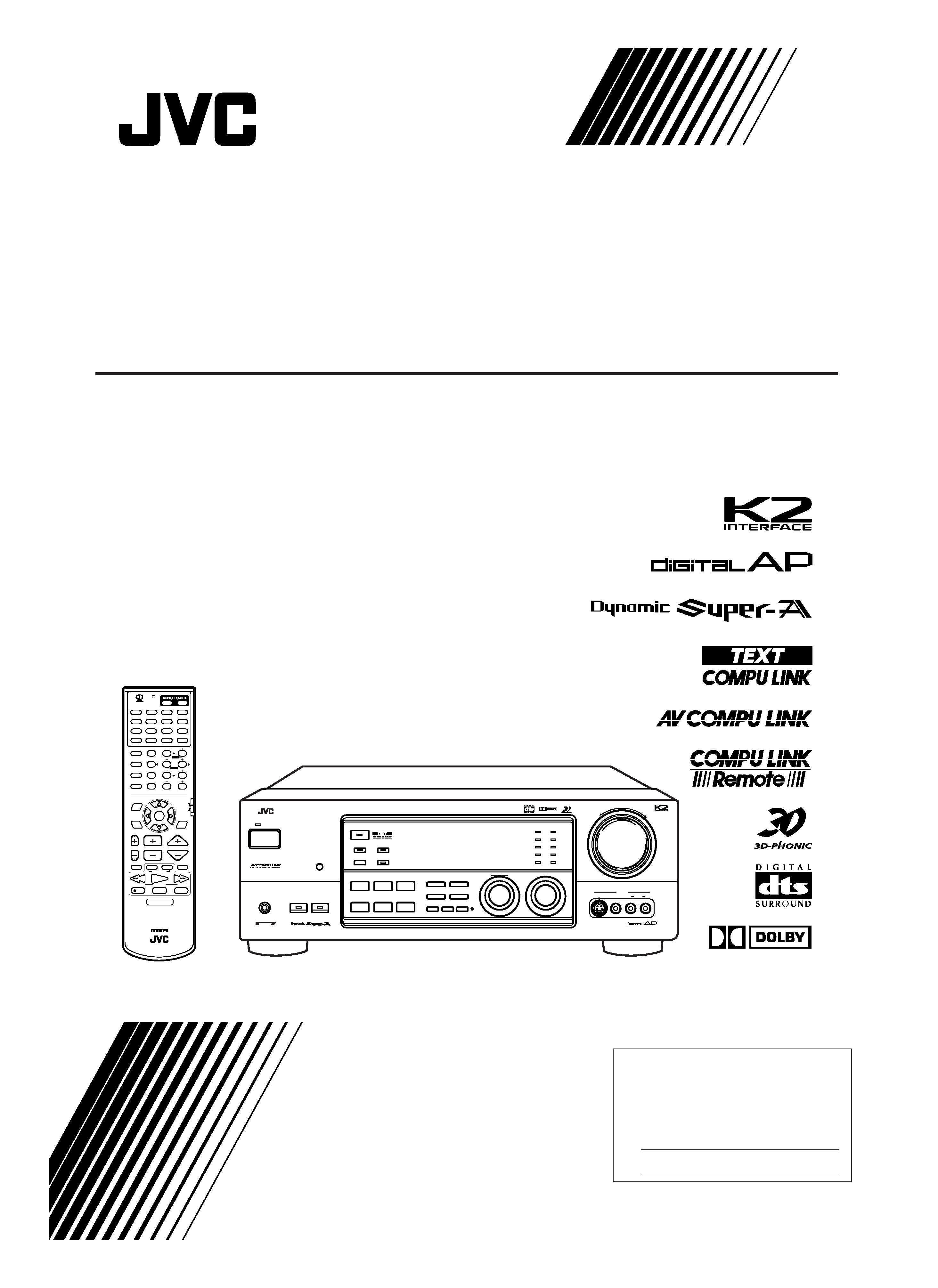
RX-9000VBK
INSTRUCTIONS
AUDIO/VIDEO CONTROL RECEIVER
DIGITAL
+
RX-9000V
AUDIO/VIDEO CONTROL RECEIVER
POWER
VIDEO
STANDBY
SPEAKERS
MAIN ROOM
SUB ROOM
MULTI ROOM
12
PHONES
SURROUND ON/OFF
DSP MODE
BALANCE/SURROUND
ADJUST
SEA MODE
SEA ADJUST
SETTING
MULTI JOG
MASTER VOLUME
SOURCE SELECTOR
S-VIDEO
VIDEO
AUDIO
LR
INPUT
ANALOG/DIGITAL
FM/AM TUNING
TUNER PRESET
TUNER/SEA MEMORY
FM MODE
DVD
TV SOUND/DBS
PHONO
TAPE/MD
VCR 1
CDR/VCR 2
FM
AM
VIDEO
LARGE
THEATER
SMALL
THEATER
LIVE
CLUB
DANCE
CLUB
CONCERT
HALL
CONCERT
ARENA
CD
SOUND SELECT
INPUT ATT.
BASS BOOST ONETOUCHOPERATION
SOURCENAME
COMPULINK
Remote
DIGITAL
1 BIT P-E-M D-D-CONVERTER
DIMMER
MAIN ROOM
ON/OFF
SUB ROOM
ON/OFF
SUB ROOM
CONTROL
RM-SRX9000J
REMOTE CONTROL
CONTROL
CHANNEL
VOLUME
TV VOL
TUNING
STOP
PAUSE
FF/
/REW
VCR 1
TV/VIDEO
TAPE/MD
MUTING
REC
PLAY
DOWN
UP
DVD
DVD MUILTI
CD
TAPE/MD
TV/DBS
VIDEO
PHONO
FM/AM
VCR 1
CDR/VCR 2 ANALOG/DIGITAL
SURROUND
CNTR TONE
CENTER
SURROUND
REAR TONE
REAR-L
CD-DISC
MODE
ON/OFF
SEA MODE
REAR-R
SOUND
TEST
SUBWOOFER
RETURN
SET
MENU
AUDIO/
TV/VCR
EXIT
TEXT
DISPLAY
SLEEP
12
3
45
6
7/P
89
10
0
+10
100+
CATV/DBS
MENU
MENU
ENTER
ENTER
STANDBY
ON
TV/CATV/DBS
VCR 1
POWER
POWER
MAIN ROOM
SUB ROOM
SUB
ROOM
MAIN
ROOM
ON/OFF
ON/OFF
FM MODE
RX-9000V[J]COVER/f
00.2.15, 2:46 PM
1
G-1
Warnings, Cautions and Others
CAUTION:
TO REDUCE THE RISK OF ELECTRIC SHOCK.
DO NOT REMOVE COVER (OR BACK)
NO USER SERVICEABLE PARTS INSIDE.
REFER SERVICING TO QUALIFIED SERVICE PERSONNEL.
RISK OF ELECTRIC SHOCK
DO NOT OPEN
The lightning flash with arrowhead symbol,
within an equilateral triangle is intended to
alert the user to the presence of uninsulated
"dangerous voltage" within the product's
enclosure
that
may
be
of
sufficient
magnitude to constitute a risk of electric
shock to persons.
The exclamation point within an equilateral
triangle is intended to alert the user to the
presence
of
important
operating
and
maintenance (servicing) instructions in the
literature accompanying the appliance.
CAUTION
WARNING: TO REDUCE THE RISK OF FIRE
OR ELECTRIC SHOCK, DO NOT EXPOSE
THIS APPLIANCE TO RAIN OR MOISTURE.
CAUTION
To reduce the risk of electrical shocks, fire, etc.:
1. Do not remove screws, covers or cabinet.
2. Do not expose this appliance to rain or moisture.
Caution POWER switch!
Disconnect the mains plug to shut the power off completely. The
POWER switch in any position does not disconnect the mains line.
The power can be remote controlled.
Caution SPEAKER LOAD SELECTOR switch!
Match the position of SPEAKER LOAD SELECTOR switch on the
back panel to the impedance of the speaker connected, to protect
from overheating.
For the remote control:
This device complies with Part 15 of the FCC Rules. Operation is
subject to the following two conditions: (1) This device may not
cause harmful interference, and (2) this device must accept any
interference received, including interference that may cause
undesired operation.
Changes
or
modifications
not
expressly
approved
by
the
manufacturer for compliance could void the user's authority to
operate the equipment.
For the main unit:
This equipment has been tested and found to comply with the limits
for a Class B digital device, pursuant to part 15 of the FCC Rules.
These limits are designed to provide reasonable protection against
harmful interference in a residential installation.
This equipment generates, uses and can radiate radio frequency
energy and, if not installed and used in accordance with the
instructions,
may
cause
harmful
interference
to
radio
communications. However, there is no guarantee that interference
will not occur in a particular installation. If this equipment does cause
harmful interference to radio or television reception, which can be
determined by turning the equipment off and on, the user is
encouraged to try to correct the interference by one or more of the
following measures:
Reorient or relocate the receiving antenna.
Increase the separation between the equipment and receiver.
Connect the equipment into an outlet on a circuit different from that
to which the receiver is connected.
Consult the dealer or an experienced radio/TV technician for help.
Changes
or
modifications
not
expressly
approved
by
the
manufacturer for compliance could void the user's authority to
operate the equipment.
For the main unit:
Declaration of Conformity
Model Number:
Trade Name:
Responsible Party:
Address:
Telephone Number:
This device complies with Part 15 of FCC Rules. Operation is
subject to the following two conditions: (1) This device may not
cause harmful interference, and (2) this device must accept any
interference received, including interference that may cause
undesired operation.
RX-9000VBK
JVC
JVC Americas Corp.
1700 Valley Road, Wayne
New Jersey 07470
973-315-5000
RX-9000VBK
Stand height
15 cm or more
Front
Spacing 15 cm
or more
Floor
Wall or
obstructions
Caution: Proper Ventilation
To avoid risk of electric shock and fire and to protect from damage.
Locate the apparatus as follows:
Front:
No obstructions open spacing.
Sides:
No obstructions in 10 cm from the sides.
Top:
No obstructions in 10 cm from the top.
Back:
No obstructions in 15 cm from the back
Bottom:
No obstructions, place on the level surface.
In addition, maintain the best possible air circulation as illustrated.
Safety-RX-9000V[J]/f
00.2.15, 2:46 PM
1

1
Table of Contents
Receiving Radio Broadcasts ........................ 29
Tuning in Stations Manually .................................................... 29
Using Preset Tuning ................................................................. 29
Selecting the FM Reception Mode ........................................... 30
Assigning Names to Preset Stations ......................................... 30
Using the SEA Modes ................................ 31
Selecting Your Favorite SEA Mode ........................................... 31
Creating Your Own SEA Mode ................................................ 31
Using the DSP Modes ................................ 32
What are the DSP Modes? ....................................................... 32
Reproducing the Sound Field ................................................... 33
Available DSP Modes According to the Speaker Arrangement ....... 34
Adjusting the Surround Modes ................................................ 35
Adjusting the DAP Modes ....................................................... 38
Activating the DSP Modes ....................................................... 40
Using the DVD MULTI Playback Mode .......... 41
Activating the DVD MULTI Playback Mode .......................... 41
Using the On-Screen Menus ........................ 42
Selecting the Main Room Source to Play ............................ 42
Selecting Different Sources for Picture and Sound .............. 42
Activating the DSP Modes ................................................... 42
Selecting the Analog or Digital Input Mode ........................ 42
Adjusting the Front Speaker Output Balance ....................... 43
Reinforcing the Bass ............................................................ 43
Attenuating the Input Signal ................................................. 43
Adjusting the Subwoofer Output Level ................................ 43
Adjusting the DSP Modes .................................................... 43
Adjusting the DVD MULTI Playback Mode ....................... 44
Selecting Your Favorite SEA Mode ..................................... 45
Creating Your Own SEA Mode ............................................ 45
Setting the Basic Setting Items ............................................ 45
Operating the Tuner .............................................................. 46
Storing the Preset Stations ................................................... 46
Assigning Names to Preset Stations ..................................... 46
COMPU LINK Remote Control System ......... 47
TEXT COMPU LINK Remote Control System .. 49
Showing the Disc Information on the TV Screen ................ 50
Searching for a Disc (Only for the CD player) .................... 51
Entering the Disc Information .............................................. 52
AV COMPU LINK Remote Control System .... 54
Operating JVC's Audio/Video Components ... 57
Operating Other Manufacturers' Video
Equipment ............................................ 60
Troubleshooting ......................................... 63
Specifications ............................................ 65
Introduction ................................................ 2
Features ...................................................................................... 2
Precautions ................................................................................. 2
Parts Identification ...................................... 3
Getting Started ........................................... 4
Before Installation ...................................................................... 4
Checking the Supplied Accessories ........................................... 4
Connecting the FM and AM Antennas ....................................... 4
Connecting the Speakers ............................................................ 5
Connecting Audio/Video Components ....................................... 6
Setting Up the RF Rod Antenna ............................................... 10
Setting Up the IR Signal Transmitter ....................................... 10
Putting Batteries in the Remote Control .................................. 11
Connecting the Power Cord ..................................................... 11
Multi-room Operations ............................... 12
Basic Operating Procedure for Main Room ............................. 13
Basic Operating Procedure for Sub-Room ............................... 14
Main Room Basic Operations ...................... 15
Turning the Power On and Off (Standby) ................................ 15
Canceling the Main Room Operations ..................................... 15
Selecting the Main Room Source to Play ................................ 16
Adjusting the Main Room Volume ........................................... 17
Activating the Main Room Front Speakers .............................. 17
Muting the Main Room Sound ................................................. 18
Reinforcing the Bass ................................................................ 18
Attenuating the Input Signal .................................................... 18
Adjusting the Subwoofer Output Level .................................... 18
Adjusting the Front Speaker Output Balance ........................... 19
Using the Sleep Timer .............................................................. 19
Changing the Display Brightness ............................................. 19
Recording a Source .................................................................. 19
Sub-Room Operations ................................. 20
Turning the Power On and Off (Standby) and Selecting
the Sub-room Operations ................................................... 20
Canceling the Sub-room Operations ........................................ 21
Selecting the Sub-room Source to Play .................................... 21
Adjusting the Sub-room Volume .............................................. 22
Activating the Sub-room Front Speakers ................................. 22
Muting the Sub-room Sound .................................................... 22
Operating the Playback Source for the Sub-room .................... 22
Basic Settings ........................................... 23
Changing the Source Name ...................................................... 23
Setting the Front Speakers Either for the Main Room
or Sub-room ....................................................................... 23
Setting the Subwoofer Information .......................................... 23
Setting the Speakers for the DSP Modes ................................. 24
Digital Input (DIGITAL IN) Terminal Setting ......................... 26
Selecting the Analog or Digital Input Mode ............................ 26
Showing the Text Information on the Display ......................... 27
Storing the Basic Settings and Adjustments -- One Touch
Operation ........................................................................... 28
Indicates the functions YOU CAN ALSO USE when
the receiver is ready for the sub-room operations.
EN01_11.RX-9000V[J]/f
00.2.15, 2:44 PM
1

2
Introduction
We would like to thank you for purchasing one of our JVC products.
Before operating this unit, read this manual carefully and thoroughly to obtain the best possible performance
from your unit, and retain this manual for future reference.
Features
Main Functions
· Dolby Digital Decoder Incorporated
You can enjoy Dolby Digital, one of the most advanced home
theater sound systems available. Dolby Digital, with five full-
range channels and a subwoofer channel, lets you enjoy the most
spectacular theater sound at home when you view movies on
DVD.
· Compatible with DTS Digital Surround
The RX-9000VBK is compatible with DTS Digital Surround as
well. DTS Digital Surround is the latest digital movie soundtrack
format that delivers 5.1-channel audio like Dolby Digital. Using a
low audio-data compression rate, it features natural, solid and
clear sound.
· Multi Room Operations
You can connect two pairs of the front speakers to the RX-
9000VBK, and use them to listen to different sources in the
different rooms (Main room and Sub-room) at the same time.
· RF/IR Multi-brand Remote Control
The remote control sends out not only IR (infrared) signals but
also RF (radio frequency) signals as coded commands to control
the receiver. The RF rod antenna can receive the RF (Radio
Frequency) signals sent from the remote control to operate the
receiver. In addition, the supplied RF signal transmitter can
transmit IR signals which could control other video components.
The remote control provided with this receiver can transmit
control signals for many manufacturers' video components.
· COMPU LINK Remote Control System
The COMPU LINK remote control system allows you to operate
other JVC audio components from this receiver.
· TEXT COMPU LINK Remote Control System
The TEXT COMPU LINK remote control system has been
developed to deal with the disc information recorded in the CD
Text and MDs. Using these information in the discs, you can
operate the CD player or MD recorder through the receiver.
· AV COMPU LINK Remote Control System
The AV COMPU LINK remote control system allows you to
operate other JVC video components from this receiver.
Main Technologies
· K2 Interface
K2 Interface eliminates jitter and ripples, achieving a drastic
reduction in digital distortion. You can obtain a natural sound field
from stereo and 5.1 channel sources.
· Dynamic Super-A
Dynamic Super-A is JVC's exclusive technology which combines
the silky, distortion-free sound of a class-A amplifier and the
robust efficiency of a class-B amplifier.
Precautions
Power sources
· When unplugging the receiver from the wall outlet, always pull
the plug, not the AC power cord.
· Do not handle the AC power cord with wet hands.
· If you are not going to operate the receiver for an extended period
of time, unplug the AC power cord from the wall outlet.
Multi-room operations
· Do not use the remote control outdoors or install the speakers
outdoors.
· When operating the receiver from the place where you cannot see
the receiver (for example, when controlling the receiver installed
in the living room, from the kitchen), pay attention to the
following not to surprise other people:
Be careful not to turn up the volume so high when controlling
the receiver without listening to the playback sound.
Be careful not to surprise other people at a sudden sound coming
out of the receiver when turning it on. (A sudden stop of the
sound may also surprise other people.)
· If the receiver operates by itself or malfunctions, the following
causes will be considered.
Interference to RF communication between the receiver and the
remote control from outside.
The remote control is operated unintentionally. For example, a
book is placed on the remote control, possibly, depressing some
buttons on the remote control.
· If your neighbour uses the same or similar RF remote control
system, the receiver may happen to receive the RF signals sent
from such an RF remote control system, which could cause your
receiver to be operated unintentionally. If this happen, stop using
the RF rod antenna and the remote control, and consult your JVC
dealer or the nearest JVC Service Center.
Others
· Should any metallic object or liquid fall into the unit, unplug the
unit and consult your dealer before operating any further.
· Do not disassemble the unit since there are no user serviceable
parts inside.
If anything goes wrong, unplug the AC power cord and consult your
JVC dealer.
EN01_11.RX-9000V[J]/f
00.2.15, 2:44 PM
2
3
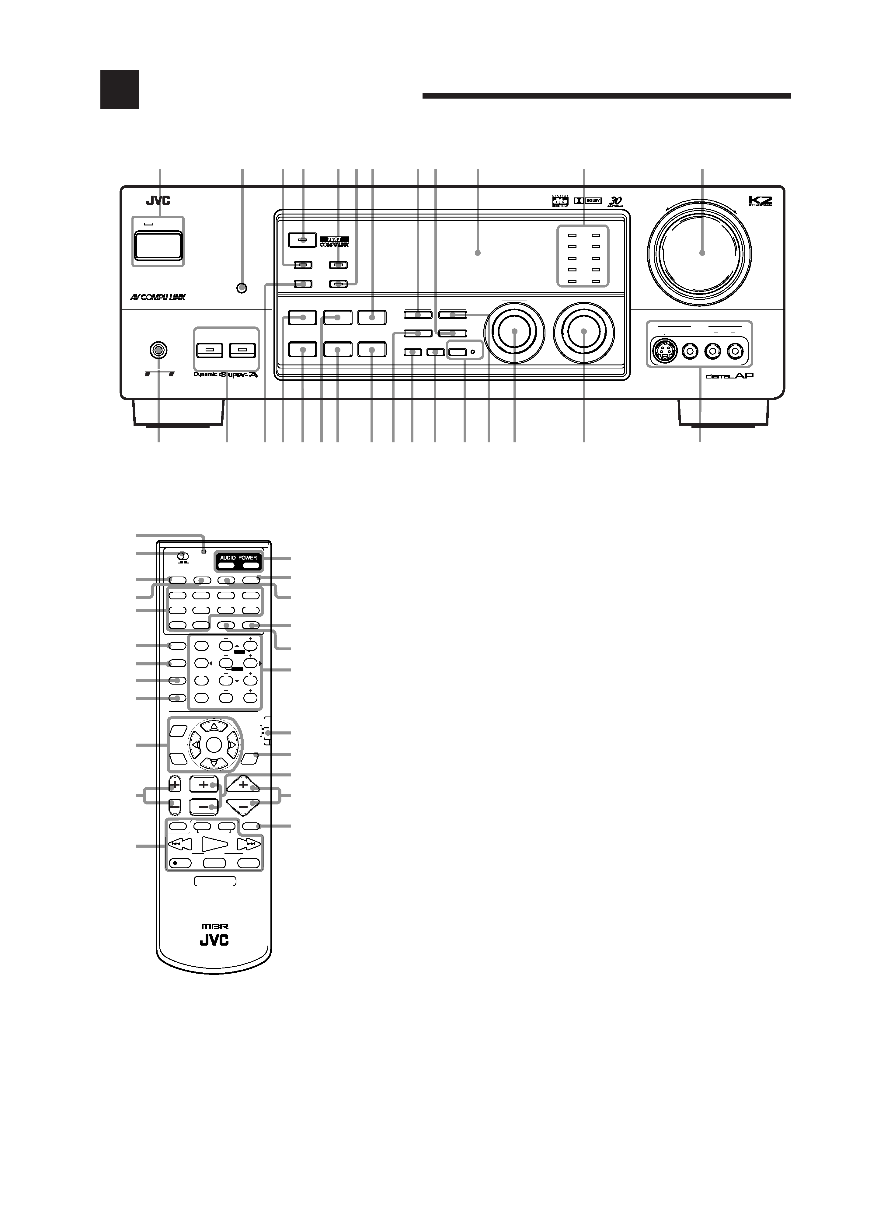
Parts Identification
Refer to the pages in parentheses for details.
Remote Control
1 Remote operation lamp (10)
Lights when transmitting a control signal.
2 Multi-room operation selector (13, 14)
3 MAIN ROOM ON/OFF button (15)
4 SUB ROOM ON/OFF button (14, 20)
5 Source selecting buttons (16, 21)
DVD, DVD MULTI, CD, TAPE/MD, TV/DBS,
VIDEO, PHONO, FM/AM, VCR 1, CDR/VCR 2
6 SURROUND ON/OFF button (35, 40)
7 SURROUND MODE button (37, 39, 40)
8 CD-DISC button (58)
9 SOUND button (18, 31, 35, 39, 41)
p On-screen operation buttons (42, 50)
MENU, SET, EXIT,
%, fi, @, #
q TV VOL +/ buttons (59, 60)
w Operating buttons for audio/video components
(57 61)
e AUDIO POWER buttons (13 15, 20)
STANDBY, ON
r VCR 1 POWER button (59, 61)
t TV/CATV/DBS POWER button (59 61)
y SLEEP button (19)
u ANALOG/DIGITAL button (27)
i · 10 keys for selecting preset channels (30)
· 10 keys for adjusting sound
(18, 31, 35, 39, 41)
· 10 keys for operating audio/video components
(57 61)
o Remote control mode selector (15, 57, 59, 60)
; TEXT DISPLAY button (50)
a CHANNEL +/ button (59 61)
s VOLUME +/ button (13, 14, 17, 22)
d MUTING button (18, 22)
Front Panel
1 POWER button and STANDBY lamp
(13 15, 20)
2 Remote sensor (10)
3 MAIN ROOM ON/OFF button and lamp (15)
4 SURROUND ON/OFF button and lamp (36, 40)
5 SUB ROOM ON/OFF button and lamp (14, 20)
6 SUB ROOM CONTROL button and lamp
(14, 21)
7 INPUT ANALOG/DIGITAL button (27)
8 FM/AM TUNING button (29) *
9 FM MODE button (30)
p Display (16)
q Source lamps (16)
w MASTER VOLUME control (13, 14, 17, 22)
e PHONES jack (17)
r Front speaker buttons and lamps
· SPEAKERS 1, SPEAKERS 2 (17)
· MAIN ROOM, SUB ROOM (22)
t DIMMER button (19)
y DSP MODE button (36, 38, 40)
u BALANCE/SURROUND ADJUST button
(19, 36, 37) *
i SEA MODE button (31)
o SEA ADJUST button (31) *
; SETTING button (23 27) *
a TUNER/SEA MEMORY button (29 31)
s SOUND SELECT/INPUT ATT. button (17, 18)
d BASS BOOST/SOURCE NAME button (18, 23)
f ONE TOUCH OPERATION button and lamp
(28)
g TUNER PRESET button (30) *
h MULTI JOG control
What this control actually does depends on
which function you are trying to adjust. Before
using this control, select the function by pressing
one of the buttons marked with *.
j SOURCE SELECTOR control (13, 14, 16, 21)
k VIDEO input jacks (8)
1 BIT P-E-M D-D-COMVERTER
12
4
5
7
8 9
p
q
w
k
j
h
g
f
d
s
a
;
o
i
u
y
r
e
SUB ROOM
CONROL
+
RX-9000V AUDIO/VIDEO CONTROL RECEIVER
POWER
VIDEO
STANDBY
SPEAKERS
MAIN ROOM
SUB ROOM
MULTI ROOM
12
PHONES
SURROUND ON/OFF
DSP MODE
BALANCE/SURROUND
ADJUST
SEA MODE
SEA ADJUST
SETTING
MULTI JOG
MASTER VOLUME
SOURCE SELECTOR
S-VIDEO
VIDEO
AUDIO
LR
INPUT
ANALOG/DIGITAL
FM/AM TUNING
TUNER PRESET
TUNER/SEA MEMORY
FM MODE
DVD
TV SOUND/DBS
PHONO
TAPE/MD
VCR 1
CDR/VCR 2
FM
AM
VIDEO
CD
SOUND SELECT
INPUT ATT.
BASS BOOST ONETOUCHOPERATION
SOURCENAME
COMPULINK
Remote
DIGITAL
DIMMER
MAIN ROOM
ON/OFF
SUB ROOM
ON/OFF
t
6
3
LARGE
THEATER
SMALL
THEATER
LIVE
CLUB
DANCE
CLUB
CONCERT
HALL
CONCERT
ARENA
RM-SRX9000J
REMOTE CONTROL
CONTROL
CHANNEL
VOLUME
TV VOL
TUNING
STOP
PAUSE
FF/
/REW
VCR 1
TV/VIDEO
TAPE/MD
MUTING
REC
PLAY
DOWN
UP
DVD
DVD MUILTI
CD
TAPE/MD
TV/DBS
VIDEO
PHONO
FM/AM
VCR 1
CDR/VCR 2 ANALOG/DIGITAL
SURROUND
CNTR TONE
CENTER
SURROUND
TEST
REAR-L
CD-DISC
MODE
ON/OFF
EFFECT
REAR-R
SOUND
SEA MODE
SUBWOOFER
RETURN
FM MODE
SET
MENU
AUDIO/
TV/VCR
EXIT
TEXT
DISPLAY
SLEEP
12
3
45
6
7/P
89
10
0
+10
100+
CATV/DBS
MENU
MENU
ENTER
ENTER
4
5
6
7
8
9
p
q
w
d
s
a
;
o
i
u
y
r
t
e
STANDBY
ON
TV/CATV/DBS
VCR 1
POWER
POWER
MAIN ROOM
SUB ROOM
SUB
ROOM
MAIN
ROOM
ON/OFF
ON/OFF
3
2
1
EN01_11.RX-9000V[J]/f
00.2.15, 2:44 PM
3