For Customer Use:
Enter below the Model No. and Serial
No. which are located either on the rear,
bottom or side of the cabinet. Retain this
information for future reference.
Model No.
Serial No.
LVT0852-002A
[C]
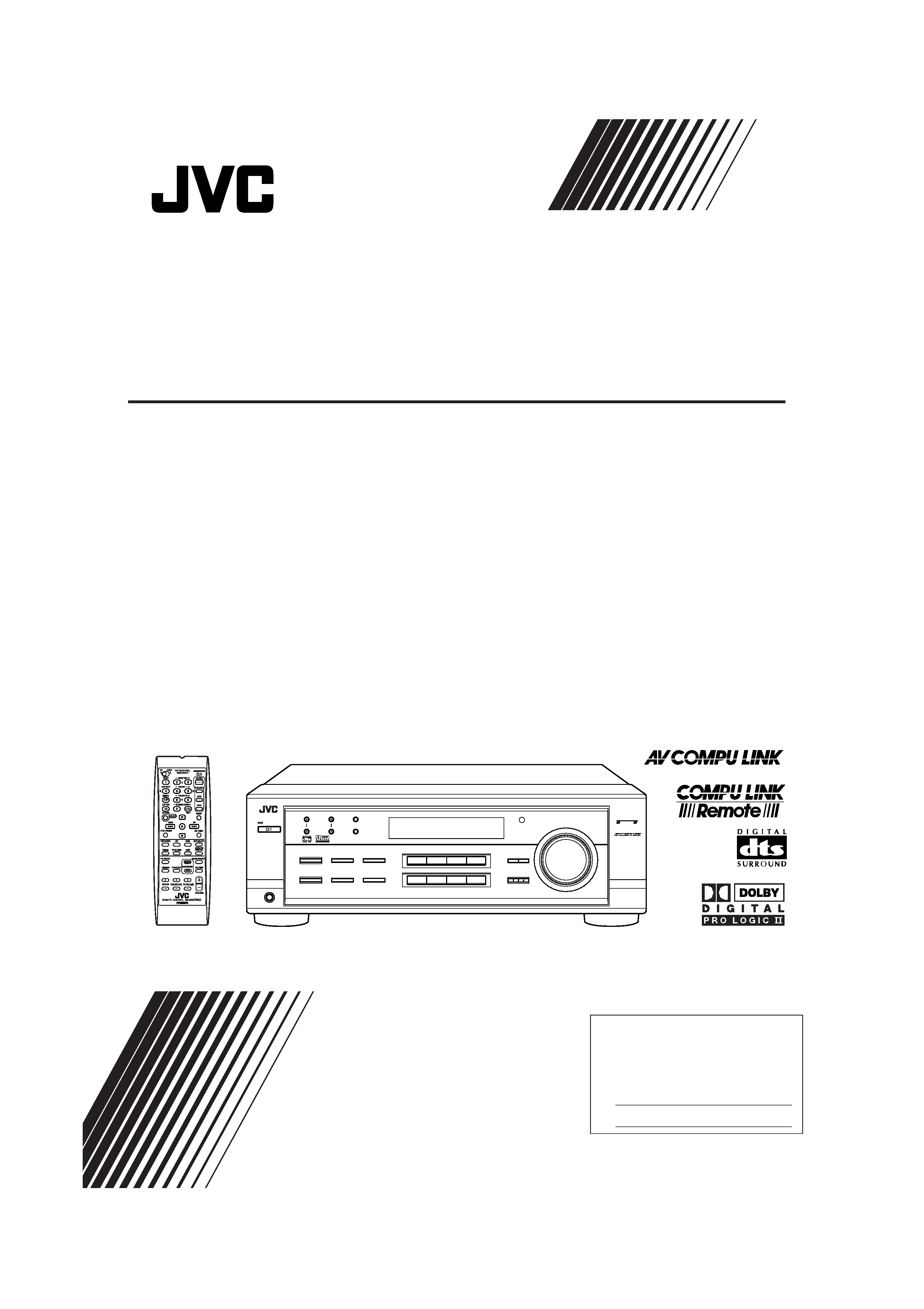
INSTRUCTIONS
RX-7520VBK
DVD
VCR
TV SOUND
ADJUST
RX-7520V AUDIO/VIDEO CONTROL RECEIVER
SETTING
MASTER VOLUME
CONTROL
DOWN
UP
CD
TAPE/CDR
SOURCE NAME
BASS BOOST
INPUT
ANALOG/DIGITAL
SPEAKERS ON/OFF
SURROUND MODE
PHONES
SURROUND ON/OFF
FM/AM TUNING
STANDBY
STANDBY/ON
FM/AM PRESET
FM MODE
MEMORY
INPUT ATT
AM
DVD MULTI
FM
12
COMPULINK
Remote
FM MODE
MANUAL D'INSTRUCTIONS
AUDIO/VIDEO CONTROL RECEIVER
RECEPTEUR DE COMMANDE AUDIO/VIDEO
RX-7520VBK[C]Cover.pm5
02.2.12, 9:30 PM
1
Warnings, Cautions and Others/
Mises en garde, précautions et indications diverses
WARNING: TO REDUCE THE RISK OF FIRE
OR ELECTRIC SHOCK, DO NOT EXPOSE
THIS APPLIANCE TO RAIN OR MOISTURE.
CAUTION
To reduce the risk of electrical shocks, fire, etc.:
1. Do not remove screws, covers or cabinet.
2. Do not expose this appliance to rain or moisture.
ATTENTION
Afin d'éviter tout risque d'électrocution, d'incendie, etc.:
1. Ne pas enlever les vis ni les panneaux et ne pas ouvrir
le coffret de l'appareil.
2. Ne pas exposer l'appareil à la pluie ni à l'humidité.
For U.S.A.
This equipment has been tested and found to comply
with the limits for a Class B digital device, pursuant to
part 15 of the FCC Rules. These limits are designed to
provide
reasonable
protection
against
harmful
interference in a residential installation.
This equipment generates, uses and can radiate radio
frequency energy and, if not installed and used in
accordance with the instructions, may cause harmful
interference to radio communications. However, there is
no guarantee that interference will not occur in a
particular installation. If this equipment does cause
harmful interference to radio or television reception,
which can be determined by turning the equipment off
and on, the user is encouraged to try to correct the
interference by one or more of the following measures:
Reorient or relocate the receiving antenna.
Increase the separation between the equipment and
receiver.
Connect the equipment into an outlet on a circuit different
from that to which the receiver is connected.
Consult the dealer or an experienced radio/TV technician
for help.
Changes or modifications not expressly approved by the
manufacturer for compliance could void the user's
authority to operate the equipment.
Caution STANDBY/ON
button!
Disconnect the mains plug to shut the power off com-
pletely. The STANDBY/ON
button in any position
does not disconnect the mains line. The power can be
remote controlled.
Attention Commutateur STANDBY/ON
!
Déconnecter la fiche de secteur pour couper
complètement le courant. Le commutateur
STANDBY/ON
ne coupe jamais complètement la
ligne de secteur, quelle que soit sa position. Le courant
peut être télécommandé.
CAUTION:
TO REDUCE THE RISK OF ELECTRIC SHOCK.
DO NOT REMOVE COVER (OR BACK)
NO USER SERVICEABLE PARTS INSIDE.
REFER SERVICING TO QUALIFIED SERVICE PERSONNEL.
RISK OF ELECTRIC SHOCK
DO NOT OPEN
The lightning flash with arrowhead symbol,
within an equilateral triangle is intended to
alert the user to the presence of uninsulated
"dangerous voltage" within the product's
enclosure that may be of sufficient
magnitude to constitute a risk of electric
shock to persons.
The exclamation point within an equilateral
triangle is intended to alert the user to the
presence of important operating and
maintenance (servicing) instructions in the
literature accompanying the appliance.
CAUTION
G-1
RX-7520VBK[C]Safety.pm5
02.2.14, 4:31 PM
1
English
Fran
ç
ais
For Canada/pour le Canada
CAUTION: TO PREVENT ELECTRIC SHOCK, MATCH
ATTENTION: POUR EVITER LES CHOCS ELECTRIQUES,
INTRODUIRE LA LAME LA PLUS LARGE DE LA FICHE DANS
LA BORNE CORRESPONDANTE DE LA PRISE ET
POUSSER JUSQUAU FOND
WIDE BLADE OF PLUG TO WIDE SLOT, FULLY INSERT
For Canada/pour Le Canada
THIS DIGITAL APPARATUS DOES NOT EXCEED THE CLASS B
LIMITS FOR RADIO NOISE EMISSIONS FROM DIGITAL APPARATUS
AS SET OUT IN THE INTERFERENCE-CAUSING EQUIPMENT
STANDARD ENTITLED "DIGITAL APPARATUS," ICES-003 OF THE
DEPARTMENT OF COMMUNICATIONS.
CET APPAREIL NUMERIQUE RESPECTE LES LIMITES DE BRUITS
RADIOELECTRIQUES APPLICABLES AUX APPAREILS NUMERIQUES
DE CLASSE B PRESCRITES DANS LA NORME SUR LE MATERIEL
BROUILLEUR; "APPAREILS NUMERIQUES", NMB-003 EDICTEE PAR
LE MINISTRE DES COMMUNICATIONS.
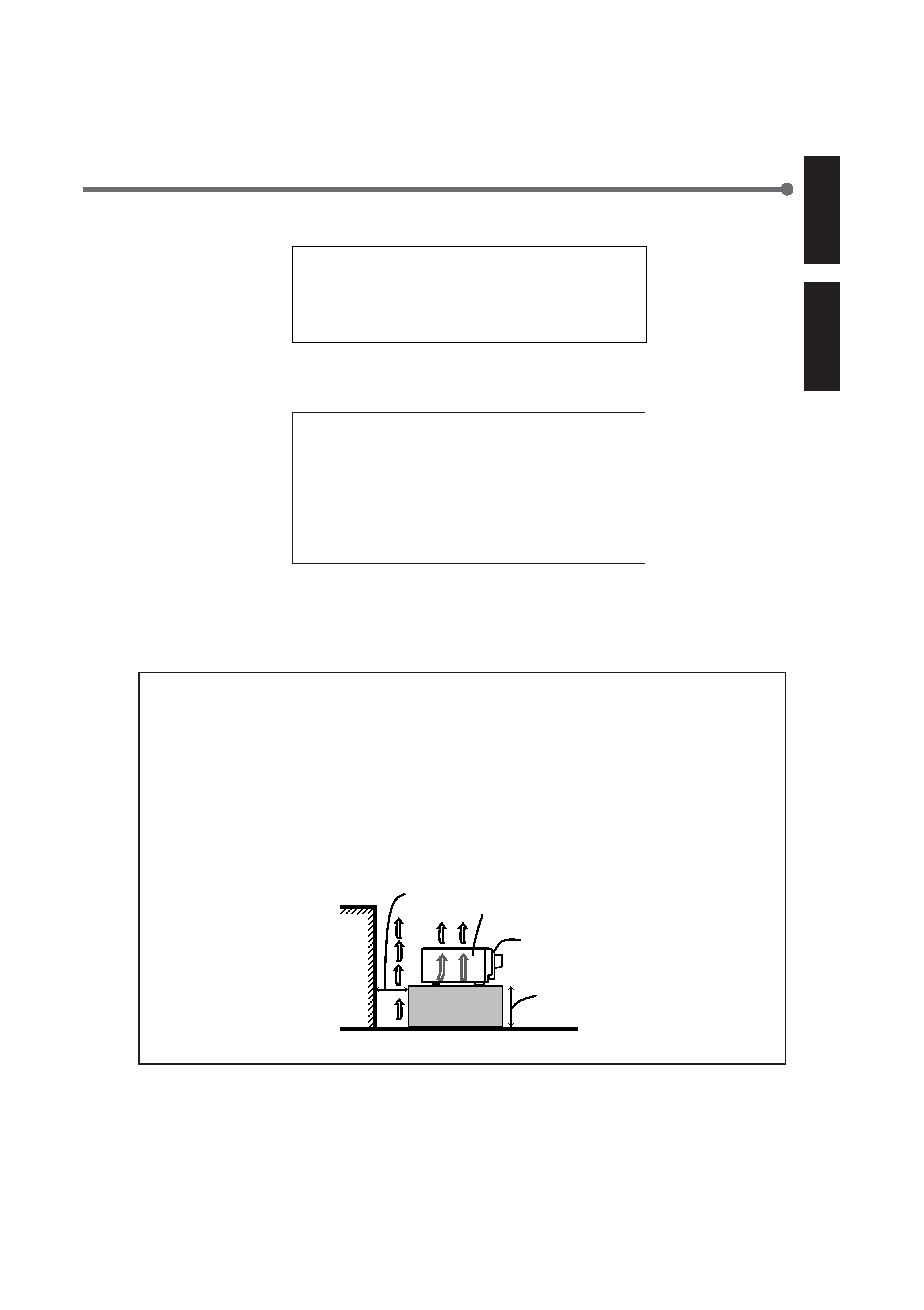
Spacing 15 cm or more
Dégagement de 15 cm ou plus
RX-7520VBK
Front
Avant
Wall or obstructions
Mur, ou obstruction
Floor
Plancher
Stand height
15 cm or more
Hauteur du socle:
15 cm ou plus
Attention: Ventilation Correcte
Pour éviter les chocs électriques, l'incendie et tout autre
dégât.
Disposer l'appareil en tenant compte des impératifs suivants
Avant:
Rien ne doit gêner le dégagement
Flancs:
Laisser 10 cm de dégagement latéral
Dessus:
Laisser 10 cm de dégagement supérieur
Arrière:
Laisser 15 cm de dégagement arrière
Dessous:
Rien ne doit obstruer par dessous; poser
l'appareil sur une surface plate.
Veiller également à ce que l'air circule le mieux possible
comme illustré.
Caution: Proper Ventilation
To avoid risk of electric shock and fire and to protect from
damage.
Locate the apparatus as follows:
Front:
No obstructions open spacing.
Sides:
No obstructions in 10 cm from the sides.
Top:
No obstructions in 10 cm from the top.
Back:
No obstructions in 15 cm from the back.
Bottom:
No obstructions, place on the level surface.
In addition, maintain the best possible air circulation as
illustrated.
G-2
RX-7520VBK[C]Safety.pm5
02.2.14, 4:31 PM
2
1
English
Table of Contents
Parts Identification ...................................... 2
Getting Started ........................................... 3
Before Installation ...................................................................... 3
Checking the Supplied Accessories ........................................... 3
Putting Batteries in the Remote Control .................................... 3
Connecting the FM and AM Antennas ....................................... 4
Connecting the Speakers ............................................................ 5
Connecting Audio/Video Components ....................................... 6
Connecting the Power Cord ....................................................... 9
Basic Operations ....................................... 10
Turning On the Power .............................................................. 10
Selecting the Source to Play ..................................................... 10
Adjusting the Volume ............................................................... 11
Selecting the Front Speakers .................................................... 11
Listening Only with Headphones ............................................. 12
Turning Off the Sounds Temporarily--Muting ........................ 12
Changing the Display Brightness ............................................. 12
Turning Off the Power with the Sleep Timer ........................... 12
Basic Settings ........................................... 14
Setting the Digital Input (DIGITAL IN) Terminals ................. 14
Selecting the Analog or Digital Input Mode ............................ 14
Setting the Video Input Terminal ............................................. 16
Setting the Speaker Information ............................................... 16
Sound Adjustments .................................... 19
Attenuating the Input Signal .................................................... 19
Adjusting the Front Speakers Output Balance ......................... 19
Adjusting the Tone ................................................................... 20
Adjusting the Subwoofer Output Level .................................... 20
Reinforcing the Bass ................................................................ 20
Tuner Operations ....................................... 21
Tuning in Stations Manually .................................................... 21
Using Preset Tuning ................................................................. 21
Selecting the FM Reception Mode ........................................... 22
Creating Realistic Sound Fields ................... 23
About Relations between Speaker Layouts and
Surround Modes ................................................................. 25
Using Dolby Pro Logic II, Dolby Digital
and DTS Digital Surround ................................................. 26
Using DAP Modes and All Channel Stereo ............................. 28
Using DVD MULTI Playback Mode ................ 30
Activating DVD MULTI Playback Mode ................................ 30
COMPU LINK Remote Control System ......... 31
AV COMPU LINK Remote Control System .... 32
Operating JVC's Audio/Video
Components .......................................... 34
Operating Audio Components .................................................. 34
Operating Video Components .................................................. 36
Operating Other Manufacturers' Video
Equipment ............................................ 37
Troubleshooting ......................................... 40
Specifications ............................................ 41
This mark indicates that the remote control CAN
ONLY be used for the operation explained.
Remote
NOT
This mark indicates that the remote control CANNOT
be used for the operation explained. Use buttons on
the front panel.
EN01-09.RX-7520V[C]f.pm5
02.2.14, 4:31 PM
1
2
English
Parts Identification
Front Panel
ADJUST
RX-7520V AUDIO/VIDEO CONTROL RECEIVER
SETTING
MASTER VOLUME
CONTROL
DOWN
UP
SURROUND MODE
PHONES
SURROUND ON/OFF
FM/AM TUNING
STANDBY
FM/AM PRESET
FM MODE
MEMORY
1
2
5
4
8
79
p
t
u
io
6
3
STANDBY/ON
DVD
VCR
TV SOUND
CD
TAPE/CDR
SOURCE NAME
AM
DVD MULTI
FM
y
r
q
w e
INPUT
ANALOG/DIGITAL
SPEAKERS ON/OFF
BASS BOOST
12
LC
S.WFR
LS
RS
CH-
S
LFE
SPK
PROLOGIC
DSP H.PHONE
AUTOMUTING
TUNED STEREO
VOLUME
BASS BOOST
INPUT ATT
SLEEP
OPERATION
DIGITAL AUTO
ANALOG
DIGITAL
LINEAR PCM
12
R
INPUT ATT
Remote Control
FM MODE
PTYPTY SEARCHPTY
7
8
4
t
;
y
6
5
p
q
i
u
9
3
1
2
w
o
r
e
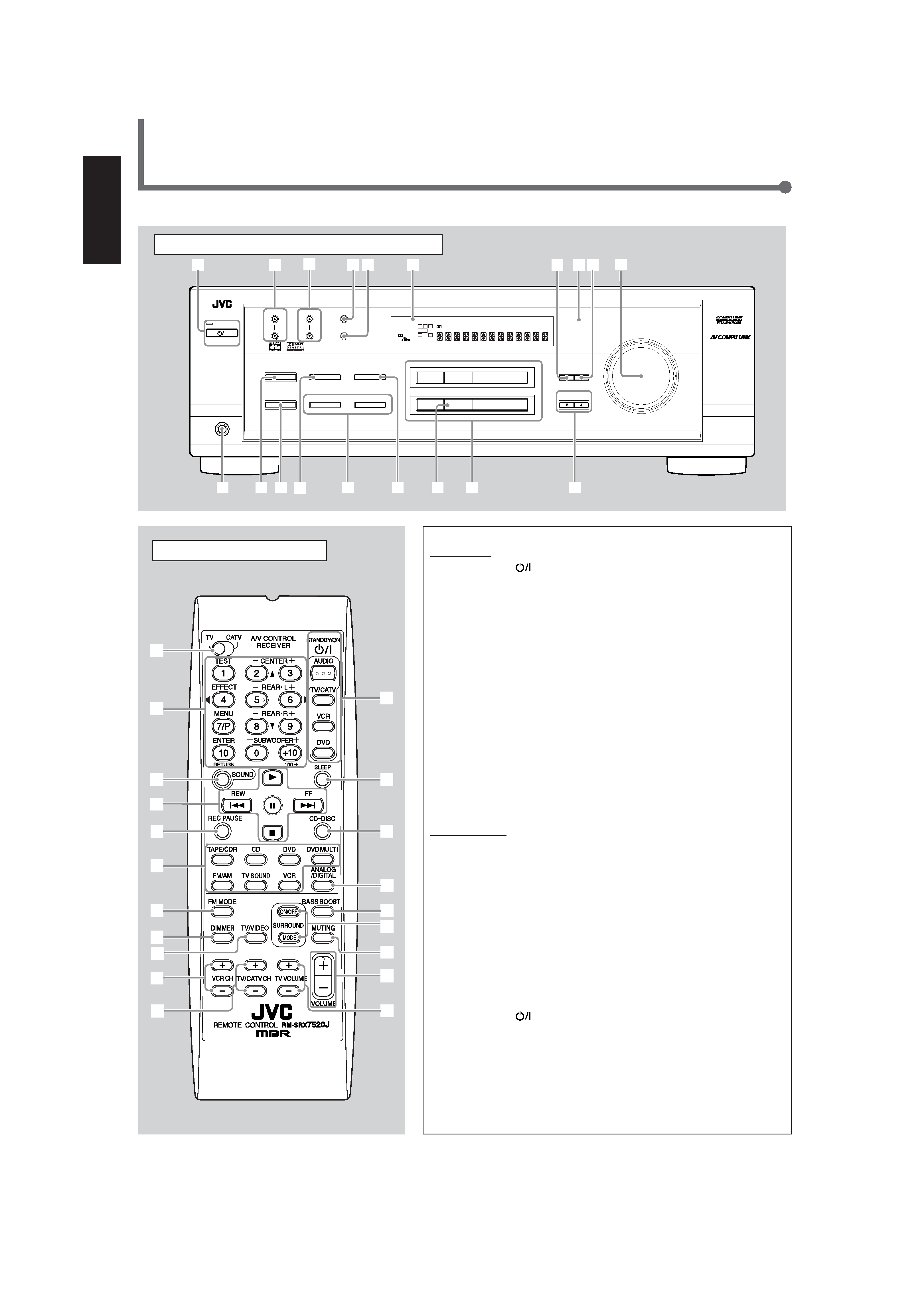
Front Panel
1 STANDBY/ON
button and STANDBY lamp (10)
2 FM/AM TUNING
5/ buttons (21)
3 FM/AM PRESET
5/ buttons (21, 22)
4 FM MODE button (22)
5 MEMORY button (21, 22)
6 Display (10)
7 ADJUST button (19, 20, 27 30)
8 Remote sensor (3)
9 SETTING button (14, 16 18)
p MASTER VOLUME control (11)
q PHONES jack (12)
w SURROUND ON/OFF button (25, 27, 29)
e SURROUND MODE button (25, 27, 29)
r · INPUT ANALOG/DIGITAL button (15)
· INPUT ATT button (19)
t SPEAKERS ON/OFF 1 and 2 buttons (11, 12)
y BASS BOOST button (20)
u SOURCE NAME button (11)
i Source selecting buttons (10, 11, 14, 21, 22, 30)
DVD MULTI, DVD, VCR, TV SOUND, CD, TAPE/CDR, FM, AM
o CONTROL UP
5/DOWN buttons (14, 16 20, 27 30)
Remote Control
1 TV/CATV selector (36, 37)
2 ·10 keys for selecting preset channels (22)
·10 keys for adjusting sound (20, 27, 28, 30, 34)
·10 keys for operating audio/video components (34 37)
3 SOUND button (20, 27, 28, 30, 34)
4 Operating buttons for audio/video components (34 36, 38, 39)
5 REC PAUSE button (35, 36, 38)
6 Source selecting buttons (10, 11, 14, 21, 22, 30, 34 39)
TAPE/CDR, CD, DVD, DVD MULTI, FM/AM, TV SOUND, VCR
7 FM MODE button (22)
8 DIMMER button (12)
9 TV/VIDEO button (36, 37)
p VCR CH (channel) +/ buttons (36, 38)
q TV/CATV CH (channel) +/ buttons (36, 37)
w STANDBY/ON
buttons (10, 33, 36 39)
AUDIO, TV/CATV, VCR, DVD
e SLEEP button (12)
r CDDISC button (35)
t ANALOG/DIGITAL button (15)
y BASS BOOST button (20)
u SURROUND ON/OFF and SURROUND MODE buttons (25, 28)
i MUTING button (12)
o VOLUME +/ button (11)
; TV VOLUME +/ buttons (36, 37)
See pages in the parentheses for details.
EN01-09.RX-7520V[C]f.pm5
02.2.14, 4:31 PM
2