For Customer Use:
Enter below the Model No. and Serial
No. which are located either on the rear,
bottom or side of the cabinet. Retain this
information for future reference.
Model No.
Serial No.
LVT0384-002A
[C]
RX-5000VBK
AUDIO/VIDEO CONTROL RECEIVER
RECEPTEUR DE CONTROL AUDIO/VIDEO
INSTRUCTIONS
MANUAL D'INSTRUCTIONS
4
1
7
4
1
RM-SR558U REMOTE CONTROL
TAPE/MD
FM/AM
VCR
DVD
SOUND
CONTROL
SLEEP
8
3
2
1
5
SURROUND
TEST
DELAY
6
5
4
EFFECT
CENTER +
5
9
8
7/P
REAR·L +
5
TV
VCR
AUDIO
CD
+10
10
REAR·R +
MENU
ENT
5
+
TV CH
TV/VIDEO
PHONO
CD-DISC
+
TV VOL.
DVD MULTI
ONE TOUCH
OPERATION
VCR CH
+
+
MUTING
VOLUME
£
POWER
RX-5000V
AUDIO/VIDEO CONTROL RECEIVER
STANDBY
PHONES
SPEAKERS
12
ADJUST
BASS BOOST
SETTING
MEMORY
DVD MULTI
CD
DVD
PHONO
VCR
TAPE/MD
SOURCE NAME
FM
SURROUND
MULTI CURSOR
INPUT ATT.
ONE TOUCH OPERATION
AM
MASTER VOLUME
+
-- OFF
_ ON
POWER
RX-5000V[C]COVER/f
00.2.3, 9:30 PM
1
Warnings, Cautions and Others/
Mises en garde, précautions et indications diverses
Caution POWER switch!
Disconnect the mains plug to shut the power off completely. The
POWER switch in any position does not disconnect the mains line.
The power can be remote controlled.
Attention Commutateur POWER!
Déconnecter la fiche de secteur pour couper complètement le
courant. Le commutateur POWER ne coupe jamais complètement
la ligne de secteur, quelle que soit sa position. Le courant peut être
télécommandé.
CAUTION
To reduce the risk of electrical shocks, fire, etc.:
1.
Do not remove screws, covers or cabinet.
2.
Do not expose this appliance to rain or moisture.
For Canada/pour le Canada
CAUTION: TO PREVENT ELECTRIC SHOCK, MATCH WIDE
BLADE OF PLUG TO WIDE SLOT, FULLY INSERT
ATTENTION: POUR EVITER LES CHOCS ELECTRIQUES,
INTRODUIRE LA LAME LA PLUS LARGE DE LA FICHE DANS LA
BORNE CORRESPONDANTE DE LA PRISE ET POUSSER
JUSQUAU FOND
ATTENTION
Afin d'éviter tout risque d'électrocution, d'incendie, etc.:
1.
Ne pas enlever les vis ni les panneaux et ne pas ouvrir le coffret de
l'appareil.
2.
Ne pas exposer l'appareil à la pluie ni à l'humidité.
RX-5000VBK
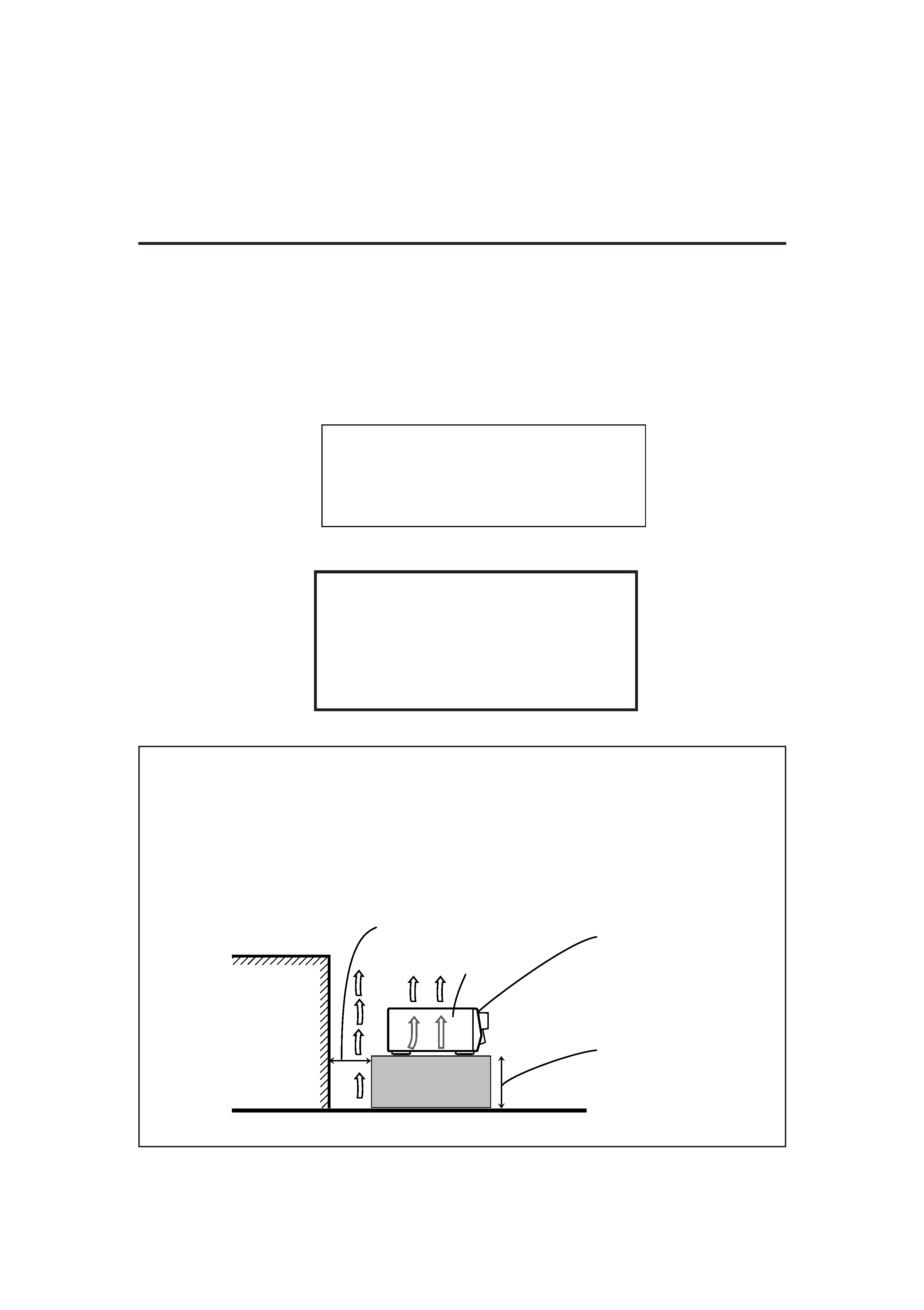
Caution: Proper Ventilation
To avoid risk of electric shock and fire and to protect from dam-
age.
Locate the apparatus as follows:
Front:
No obstructions open spacing.
Sides:
No obstructions in 10 cm from the sides.
Top:
No obstructions in 10 cm from the top.
Back:
No obstructions in 15 cm from the back
Bottom:
No obstructions, place on the level surface.
In addition, maintain the best possible air circulation as illustrated.
Attention: Ventilation Correcte
Pour éviter les chocs électriques, l'incendie et tout autre dégât.
Disposer l'appareil en tenant compte des impératifs suivants
Avant:
Rien ne doit gêner le dégagement
Flancs:
Laisser 10 cm de dégagement latéral
Dessus:
Laisser 10 cm de dégagement supérieur
Arrière:
Laisser 15 cm de dégagement arrière
Dessous:
Rien ne doit obstruer par dessous; poser l'appareil
sur une surface plate.
Veiller également à ce que l'air circule le mieux possible comme
illustré.
Wall or obstructions
Mur, ou obstruction
Spacing 15 cm or more
Dégagement de 15 cm ou plus
Front
Avant
Stand height 15 cm or more
Hauteur du socle: 15 cm ou plus
Floor
Plancher
RX-5000V[C]SAFETY/f
00.2.2, 10:49 AM
1

1
English
Table of Contents
Parts Identification ...................................... 2
Getting Started ........................................... 3
Before Installation ...................................................................... 3
Checking the Supplied Accessories ........................................... 3
Connecting the FM and AM Antennas ....................................... 3
Connecting the Speakers ............................................................ 4
Connecting Audio/Video Components ....................................... 5
Connecting the Power Cord ....................................................... 7
Putting Batteries in the Remote Control .................................... 7
Basic Operations ......................................... 8
Turning the Power On and Off (Standby) .................................. 8
Selecting the Source to Play ....................................................... 8
Adjusting the Volume ................................................................. 9
Selecting the Front Speakers ...................................................... 9
Muting the Sound ....................................................................... 9
Recording a Source .................................................................... 9
Attenuating the Input Signal .................................................... 10
Adjusting the Front Speaker Output Balance ........................... 10
Reinforcing the Bass ................................................................ 10
Adjusting the Tone ................................................................... 10
Basic Settings ........................................... 11
Changing the Source Name ...................................................... 11
Setting Center and Rear Speakers for the DSP Modes ............ 11
Storing the Basic Settings and Adjustments -- One Touch
Operation ........................................................................... 12
Using the Sleep Timer .............................................................. 12
Receiving Radio Broadcasts ........................ 13
Tuning in Stations Manually .................................................... 13
Using Preset Tuning ................................................................. 13
Selecting the FM Reception Mode ........................................... 14
Using the DSP Modes ................................ 15
Available DSP Modes According to the Speaker Arrangement .. 16
Adjusting the 3D-PHONIC Modes .......................................... 17
Adjusting the DAP Modes ....................................................... 17
Adjusting the Surround Modes -- Dolby Surround and JVC
Theater Surround ............................................................... 18
Activating the DSP Modes ....................................................... 19
Using the DVD MULTI Playback Mode .......... 20
Activating the DVD MULTI Playback Mode .......................... 20
COMPU LINK Remote Control System ......... 21
Operating JVC's Audio/Video Components ... 22
Troubleshooting ......................................... 24
Specifications ............................................ 25
EN01-07.RX-5000V[C]/F
00.2.3, 8:16 PM
1
2
English
Parts Identification
Become familiar with the buttons and controls on the receiver before use.
Refer to the pages in parentheses for details.
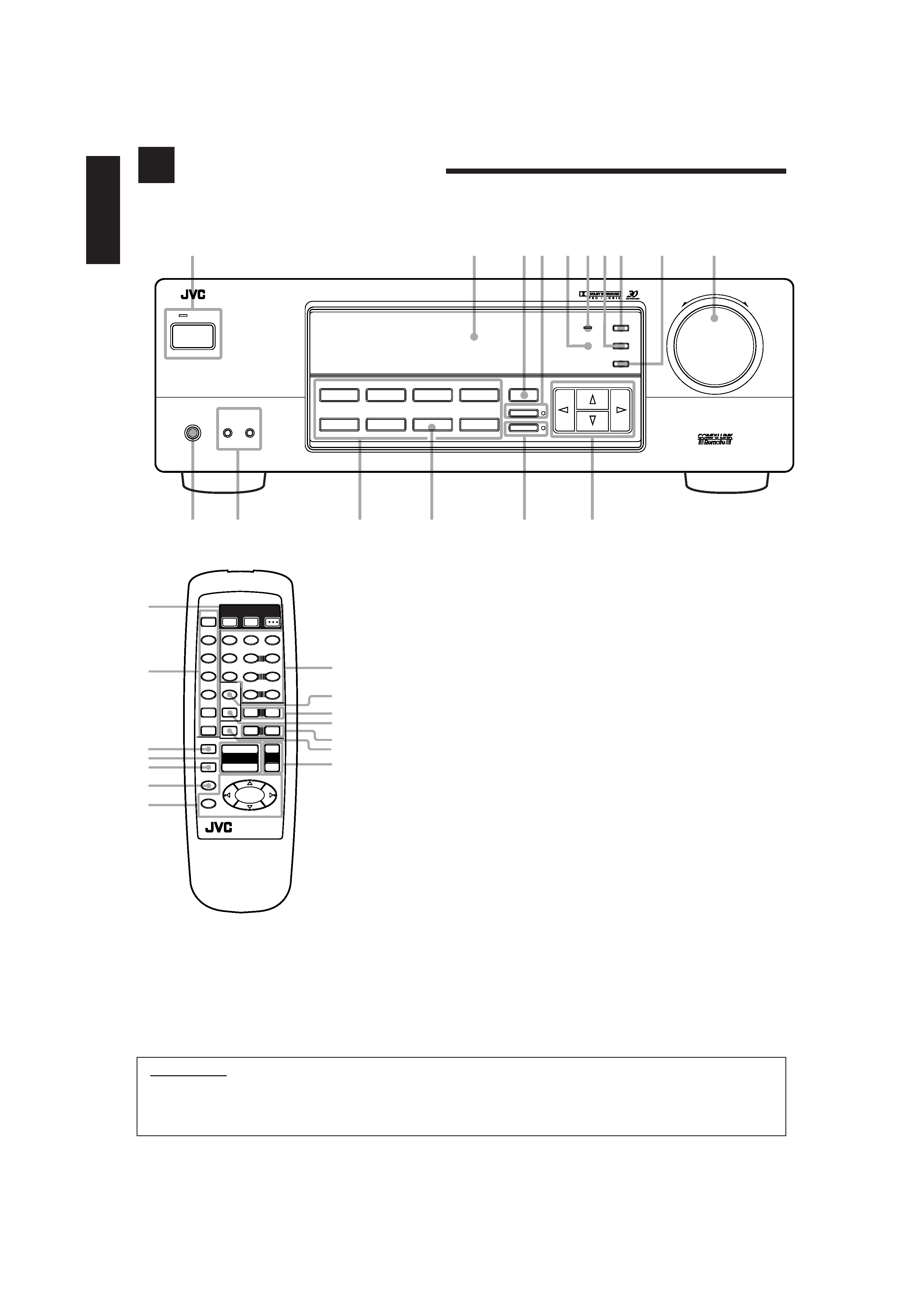
Front Panel
1 POWER button and STANDBY lamp (8)
2 Display (8)
3 SURROUND button (16)
4 ONE TOUCH OPERATION button and
lamp (12)
5 Remote sensor (7)
6 BASS BOOST lamp (10)
7 SETTING button (11)*
8 ADJUST button (10)*
9 MEMORY button (13)
p MASTER VOLUME control (9)
q Cursor control buttons
w INPUT ATT. button and lamp (10)
e SOURCE NAME button (11)
r Source selecting buttons (8)
DVD MULTI, DVD, VCR, FM*,AM*,
TAPE/MD, PHONO, CD
t SPEAKERS 1/2 buttons (9)
y PHONES jack (9)
IMPORTANT:
To use the Cursor control buttons (q) on the front panel:
What these buttons actually do depends on which function you are trying to adjust. Before using these buttons, select the function by
pressing one of the buttons marked with *.
Remote Control
1 POWER buttons (8, 23)
TV, VCR, AUDIO
2 Source selecting buttons (8)
CD, TAPE/MD, FM/AM, VCR, DVD,
DVD MULTI, PHONO
3 ONE TOUCH OPERATION button (12)
4 VOLUME +/ buttons (9)
5 MUTING button (9)
6 SLEEP button (12)
7 Operating buttons for audio/video
components (22)
8 · 10 keys for selecting preset channel (14,
22)
· 10 keys for adjusting sound (12, 17, 22)
· 10 keys for operating other components
(22)
9 SOUND CONTROL button (12, 17, 22)
p TV VOL. /+ buttons (23)
q CD-DISC button (22)
w TV CH /+ buttons (23)
e TV/VIDEO button (23)
r VCR CH +/ buttons (23)
RX-5000V
AUDIO/VIDEO CONTROL RECEIVER
STANDBY
PHONES
SPEAKERS
1
-- OFF
_ ON
2
ADJUST
SETTING
MEMORY
DVD MULTI
CD
DVD
PHONO
VCR
TAPE/MD
SOURCE NAME
FM
SURROUND
MULTI CURSOR
INPUT ATT.
ONE TOUCH OPERATION
AM
MASTER VOLUME
+
12
7
35
48
69
p
q
w
e
r
t
y
BASS BOOST
POWER
6
1
2
4
1
7
4
1
RM-SR558U REMOTE CONTROL
SLEEP
8
+
TV CH
TV/VIDEO
PHONO
CD-DISC
+
TV VOL.
DVD MULTI
ONE TOUCH
OPERATION
VCR CH
+
+
MUTING
VOLUME
£
+
TAPE/MD
FM/AM
VCR
DVD
SOUND
CONTROL
3
2
1
5
SURROUND
TEST
DELAY
6
5
4
EFFECT
CENTER +
5
9
8
7/P
REAR·L +
5
TV
VCR
AUDIO
CD
+10
10
REAR·R +
MENU
ENT
5
4
5
8
r
3
q
w
p
7
9
e
POWER
EN01-07.RX-5000V[C]/F
00.2.3, 8:16 PM
2
3
English
AM
LOOP
ANTENNA
AM
EXT
FM
75
COAXIAL
AM
LOOP
ANTENNA
AM
EXT
FM
75
COAXIAL
ANTENNA
AM
EXT
AM
LOOP
FM 75
COAXIAL
Getting Started
This section explains how to connect audio/video components and speakers to the receiver, and how to connect the
power supply.
Before Installation
General
· Be sure your hands are dry.
· Turn the power off to all components.
· Read the manuals supplied with the components you are going to
connect.
Locations
· Install the receiver in a location that is level and protected from
moisture.
· The temperature around the receiver must be between 5° and
35°C (23°F and 95°F).
· Make sure there is good ventilation around the receiver. Poor
ventilation could cause overheating and damage the receiver.
Handling the receiver
· Do not insert any metal object into the receiver.
· Do not disassemble the receiver or remove screws, covers, or
cabinet.
· Do not expose the receiver to rain or moisture.
Checking the Supplied Accessories
Check to be sure you have all of the following items, which are
supplied with the receiver.
The number in the parentheses indicates quantity of the pieces
supplied.
· Remote Control (1)
· Batteries (2)
· AM Loop Antenna (1)
· FM Antenna (1)
If anything is missing, contact your dealer immediately.
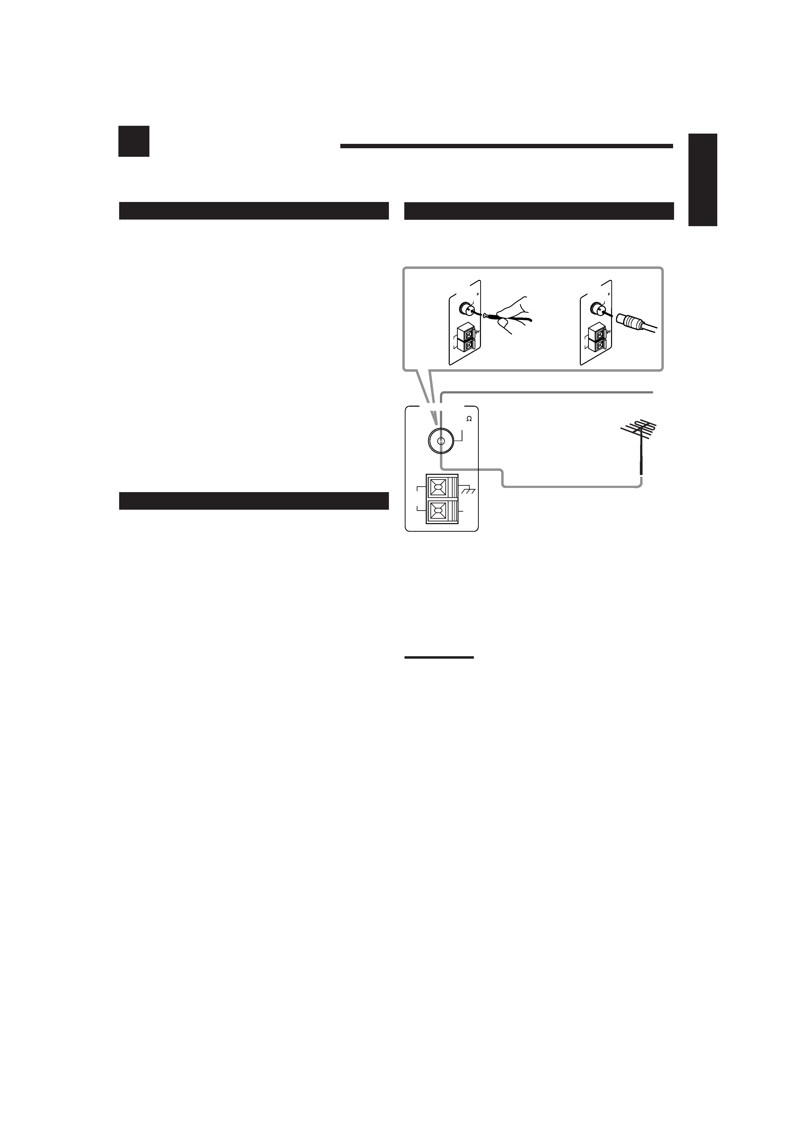
A
B
A. Using the Supplied FM Antenna
The FM antenna provided can be connected to the FM 75
COAXIAL terminal as temporary measure.
B. Using the Standard Type Connector (Not Supplied)
A standard type connector should be connected to the FM 75
COAXIAL terminal.
Note:
If reception is poor, connect the outside antenna.
Before attaching a 75
coaxial cable (the kind with a round wire
going to an outside antenna), disconnect the supplied FM antenna.
FM Antenna
Connecting the FM and AM Antennas
FM Antenna Connections
Extend the supplied FM antenna horizontally.
Outside FM Antenna Cable
EN01-07.RX-5000V[C]/F
00.2.3, 8:16 PM
3