INSTRUCTIONS
(A)
REMOTE
CONTROL
UNIT
RM-P2580
is
a
registered
trademark
owned
by
VICTOR
COMPANY
OF
JAPAN,
LTD.
is
a
registered
trademark
in
Japan,
the
U.S.A.,
the
U.K.
and
many
other
countries.
©
2003
VICTOR
COMPANY
OF
JAPAN,
LIMITED
RM-P2580 REMOTE CONTROL UNIT
R
SETUP
MENUMENU
SETSET
SPEEDSPEED
IRIS
AF
FOCUS
ZOOM
OPENOPEN
FAR
TELE
CLEARCLEAR
/ALL/ALL
7
4
1
8
0
5
2
9
6
3
ENTERENTER
AUTOAUTO
PANPAN
HOMEHOME
FUNC-FUNC-
TIONTION
CAMERA
POSI-POSI-
TIONTION
PRESET
SEQ
CLOSECLOSE
NEARNEAR
WIDEWIDE
AUTOAUTO
F-1F-1
F-2F-2
F-3F-3
PAN/TILT
LENS
CAMERA/POSITION
ALARMALARM
CAMERACAMERA
POSITIONPOSITION
REMOTE
CONTROL
UNIT
RM-P2000
KEY
LOCK
KEY
LOCK
E
model
LWT0111
U
model
LWT0110
R
Printed
in
Japan
E
model
LWT0111
U
model
LWT0110
SETUP
MENUMENU
SET
SPEED
IRIS
AF
FOCUS
ZOOM
OPENOPEN
FARFAR
TELETELE
CLEARCLEAR
/HOME/HOME
7
4
1
8
0
5
2
9
6
3
ENTERENTER
AUTOAUTO
PANPAN
OPTIONOPTION
1
OPTIONOPTION
2
CAMERACAMERA
POSI-POSI-
TIONTION
AUTOAUTO
PATROLPATROL
CLOSECLOSE
NEARNEAR
WIDE
AUTOAUTO
F-1
F-2F-2
F-3F-3
PAN/TILT
LENS
CAMERA/POSITION
ALARMALARM
POPO
WERWER
CAMERACAMERA
POSITIONPOSITION
REMOTE
CONTROL
UNIT
RM-P2580
KEY
LOCK
KEY
LOCK
INTR
ODUCTION
B
ASIC
OPERA
TIONS
APPLIED
OPERA
TIONS
O
THER
CONNECTIONS
MENU
SCREEN
SETUPS
E-2
Changes
or
modifications
not
approved
by
JVC
could
void
the
user's
authority
to
operate
the
equipment.
This
unit
is
designed
for
professional
use
only
.
SAFETY
PRECAUTIONS
W
ARNING:
TO
PREVENT
FIRE
OR
SHOCK
HAZARD
,D
O
NO
T
EXPOSE
THIS
APPLIANCE
TO
RAIN
OR
MOISTURE.
IMPOR
T
ANT
The
wires
in
this
mains
lead
are
coloured
in
accordance
with
the
following
code:
GREEN
-
AND
-
YELLOW
:
EAR
TH
BLUE:
NEUTRAL
BROWN:
LIVE
As
the
colours
of
the
wires
in
the
mains
lead
of
this
appara-
tus
may
not
correspond
with
the
coloured
markings
identi-
fying
the
terminals
in
your
plug.
proceed
as
follows.
The
wire
which
is
coloured
GREEN-AND-YELLOW
must
be
connected
to
the
terminal
in
the
plug
which
is
marked
with
the
letter
E
or
by
the
safety
earth
symbol
or
col-
oured
GREEN
or
GREEN-AND
-YELLOW
.
The
wire
which
is
coloured
BLUE
must
be
connected
to
the
terminal
which
is
marked
with
the
letter
N
or
which
is
coloured
BLACK.
The
wire
which
is
coloured
BROWN
must
be
connected
to
the
terminal
which
is
marked
with
the
letter
L
or
coloured
RED.
W
ARNINGTHIS
APP
ARA
TUS
MUST
BE
EAR
THED
CA
UTION
RISK
OF
ELECTRIC
SHOCK
DO
NOT
OPEN
CAUTION
:
T
O
REDUCE
THE
RISK
OF
ELECTRIC
SHOCK,
DO
NOT
REMOVE
COVER
(OR
BACK).
NO
USER
SER
VICEABLE
P
A
R
TS
INSIDE.
REFER
SER
VICING
T
O
QUALIFIED
SER
VICE
PERSONNEL.
Inf
ormation
f
or
USA
This
device
complies
with
Part
15
of
the
FCC
Rules.
Changes
or
modifications
not
approved
by
JVC
could
void
the
user's
authority
to
operate
the
equipment.
The
lightning
flash
with
arrowhead
symbol,
within
an
equilateral
triangle
is
intended
to
alert
the
user
to
the
presence
of
uninsulated
"dan-
gerous
voltage"
within
the
product's
enclosure
that
may
be
of
suf
ficient
magnitude
to
consti-
tute
a
risk
of
electric
shock
to
persons.
The
exclamation
point
within
an
equilateral
tri-
angle
is
intended
to
alert
the
user
to
the
pres-
ence
of
important
operating
and
maintenance
(servicing)
instructions
in
the
literature
accom-
panying
the
appliance.
W
ARNING:
T
O
REDUCE
THE
RISK
OF
FIRE
OR
ELECTRIC
SHOCK,
DO
NO
T
EXPOSE
THIS
APPLIANCE
T
O
RAIN
OR
MOISTURE.
Changes
or
modifications
not
approved
by
JVC
could
void
the
user's
authority
to
operate
the
equipment.
This
unit
is
designed
for
professional
use
only
.
A
VER
TISSEMENT
:
POUR
EVITER
LES
RISQ
UES
D'INCENDIE
OU
D'ELECTR
OCUTION,
NE
P
AS
EXPOSER
L
'APP
AREIL
A
L
'HUMIDITE
OU
A
LA
PLUIE.
INFORMA
TION
(FOR
CANAD
A)
RENSEIGNEMENT
(POUR
CANAD
A)
This
Class
B
digital
apparatus
meets
all
requirements
of
the
canadian
Interference-Causing
Equipment
Regulations.
Cet
appareil
numérique
de
la
classe
B
respecte
toutes
les
exigences
du
Réglement
sur
le
matériel
brouilleur
du
Canada.
Due
to
design
modifications,
data
given
in
this
instruction
book
are
subject
to
possible
change
without
prior
notice.
E
model
U
model
E-3
1.
INTR
ODUCTION
CONTENTS
.......................................................................................................................
...................
3
FEA
TURES
.......................................................................................................................
....................
4
ACCESSORIES
....................................................................................................................
...............
4
PRECAUTIONS
FOR
PROPER
OPERA
TION
.....................................................................................
4
CONTROLS,
CONNECT
ORS
AND
INDICA
T
ORS
...............................................................................
5
2.
B
ASIC
OPERA
TIONS
CAMERA
SELECTION
.......................................................................................................................
10
POSITION
SELECTION
.....................................................................................................................
11
MANUAL
OPERA
TION
...............................................................................................................
........
12
AUT
O
SEQUENCE
OPERA
TION
.......................................................................................................
13
AUT
O
P
AN
OPERA
TION
.............................................................................................................
.......
14
AUT
O
P
A
TROL
OPERA
TION
..........................................................................................................
....
15
KEY
LOCK
(PREVENTION
OF
OPERA
TION
MIST
AKE)
...................................................................
16
3.
APPLIED
OPERA
TIONS
ALARM
OPERA
TION
................................................................................................................
.........
17
DA
T
A
OUTPUT
....................................................................................................................
...............
18
CAMERA
SWITCHING
OPERA
TION
.................................................................................................
18
4.
CONNECTIONS
BASIC
SYSTEM
(A
MODE)
...............................................................................................................
19
APPLIED
SYSTEM
(B
MODE)
...........................................................................................................
21
REAR
PANEL
CONNECT
ORS
..........................................................................................................
23
5.
MENU
SCREEN
SETUPS
FLOW
OF
MENUS
.............................................................................................................................
25
MENU
OPERA
TION
.................................................................................................................
..........
26
SETUP
SCREEN
(MAIN
MENU)
POSITION
SETUP
SCREEN
..........................................................................................................
27
CAMERA
SCREEN
.........................................................................................................................
28
CONTROL
UNIT
SCREEN
............................................................................................................
.
28
OPTION
SCREEN
.....................................................................................................................
29
DA
T
A
I/O
SCREEN
................................................................................................................
....
30
ALARM
SCREEN
......................................................................................................................
32
AUT
O
SEQUENCE
SCREEN
....................................................................................................
32
6.
O
THER
TROUBLESHOOTING
........................................................................................................................
33
SPECIFICA
TIONS
.................................................................................................................
.............
34
1.
INTRODUCTION
CONTENTS
Thank
you
for
purchasing
the
JVC
RM-P2580.
These
instructions
are
for
the
RM-P2580E/U
.
E-4
Presetting
of
up
to
100
positions
(including
the
home
positions)
each,
for
up
to
8
combination
cameras.
Built-in
P
AN,
TIL
T
and
ZOOM
control
for
up
to
8
cameras.
RS-485
connection
system
enables
cascaded
connection
of
cameras.
Built-in
sequential
switcher
.
Alarm
input
terminals.
Data
I/O
terminals
for
interlocked
operation
with
external
peripherals.
A
CCESSORIES
1.
INTRODUCTION
FEA
TURES
Precautions
for
the
PRESET
SEQUENCE
and
A
U
TO
P
AN
Operations
The
life-span
of
the
PRESET
SEQUENCE
and
AUT
O
P
A
N
functions
is
dependent
on
which
camera
model
is
used
in
combination
with
this
unit.
When
using
the
TK-C655
and
TK-C676
cameras,
the
guar-
anteed
zoom
lens
operation
count
is
200,000
times.
If
the
zoom
lens
operation
is
used
often,
the
life-span
of
the
PRE-
SET
SEQUENCE
and
AUT
O
P
AN
functions
may
be
much
less
than
expected.
(Example)
Assuming
that
a
ZOOM
operation
is
performed
every
minute
and
the
camera
is
used
24
hours
a
day:
200,000
x
2
(times)
÷
60
(minutes)
÷
24
(hours)
=
277
(days)
Total
operations
count
Daily
operating
hours
For
other
camera
models,
please
refer
to
the
Handling
&
Installation
Instructions
manuals
of
the
camera
in
use.
Do
not
install
the
unit
in
a
place
subject
to
direct
sunlight,
excessive
moisture,
dust,
or
vibrations
where
ventilation
is
poor
.
Be
careful
of
strong
radio
waves
and
magnetism:
If
the
unit
is
near
a
source
of
strong
magnetism,
such
as
a
radio
or
TV
transmission
antenna,
power
transformer
or
motor
,the
video
signal
may
be
subject
to
interference.
Always
use
the
power
cord
provided
with
or
specified
for
this
unit.
CLEAN
EXTERIOR
Wipe
gently
with
a
soft
cloth.
Put
cloth
in
diluted
mild
soap
and
wring
it
well
to
wipe
of
f
heavy
dirt.
Then
wipe
again
with
a
dry
cloth.
To
save
energy
,be
sure
to
turn
of
fthe
system
when
not
in
use.
Power
cord
(2
m)
Ferrite
Core
Instructions
(this
manual)
INSTRUCTIONS
BEDIENUNGSANLEITUNG
MANUEL
D'INSTRUCTIONS
RE
M
O
T
E
CO
NT
R
O
L
U
NIT
FE
RN
BE
D
IE
NU
NG
SE
INH
EIT
C
O
M
M
AN
D
E
A
D
ISTA
NC
E
RM-P2580
S
E
T
U
P
M
E
N
U
MENU
S
E
T
SET
S
P
E
E
D
S
PE
E
D
IR
IS
A
F
F
O
C
U
S
Z
O
O
M
O
P
E
N
OPEN
F
A
R
FA
R
T
E
L
E
TELE
C
L
E
A
R
C
L
E
A
R
/A
L
L
/A
L
L
7
4
1
8
0
5
2
9
6
3
E
N
T
E
R
EN
TER
A
U
T
O
AU
T
O
P
A
N
P
AN
H
O
M
E
HOME
F
U
N
C
-
FU
NC
-
T
IO
N
T
ION
C
A
M
E
R
A
C
AMER
A
P
O
S
I-
POS
I-
T
IO
N
TI
O
N
P
R
E
S
E
T
PRE
S
ET
S
E
Q
S
EQ
C
L
O
S
E
CLOSE
N
E
A
R
NE
AR
W
ID
E
W
ID
E
A
U
T
O
AUTO
F
-1
F-
1
F
-2
F
-2
F
-3
F-
3
P
A
N
/T
IL
T
L
E
N
S
C
A
M
E
R
A
/P
O
S
IT
IO
N
A
L
A
R
M
A
L
A
RM
C
A
M
E
R
A
CAM
ERA
P
O
S
IT
IO
N
P
O
SI
T
IO
N
R
E
M
O
T
E
C
O
N
T
R
O
L
U
N
IT
R
M
-P
2
0
0
0
K
E
Y
L
O
C
K
K
E
Y
LOCK
S
C
9
6
8
5
9
-0
0
1
R
S
E
T
U
P
M
E
N
U
M
ENU
S
E
T
SE
T
S
P
E
E
D
SP
E
ED
IR
IS
A
F
F
O
C
U
S
Z
O
O
M
O
P
E
N
O
PE
N
F
A
R
FAR
T
E
L
E
T
ELE
C
L
E
A
R
C
LEA
R
/H
O
M
E
/HOME
7
4
1
8
0
5
2
9
6
3
E
N
T
E
R
E
NT
ER
A
U
T
O
AU
TO
P
A
N
P
A
N
O
P
T
IO
N
O
P
T
IO
N
1
O
P
T
IO
N
O
PT
IO
N
2
C
A
M
E
R
A
CA
MERA
P
O
S
I-
P
OSI-
T
IO
N
T
ION
A
U
T
O
AU
T
O
P
A
T
R
O
L
P
AT
RO
L
C
L
O
S
E
CLO
S
E
N
E
A
R
N
E
AR
W
ID
E
WIDE
A
U
T
O
A
U
T
O
F
-1
F
-1
F
-2
F-2
F
-3
F-3
P
A
N
/T
IL
T
L
E
N
S
C
A
M
E
R
A
/P
O
S
IT
IO
N
A
L
A
R
M
A
L
A
R
M
P
O
PO
W
E
R
WER
C
A
M
E
R
A
C
A
M
ERA
P
O
S
IT
IO
N
P
O
S
ITI
O
N
R
E
M
O
T
E
C
O
N
T
R
O
L
U
N
IT
R
M
-P
2
5
8
0
K
E
Y
L
O
C
K
K
EY
L
O
CK
IN
T
R
O
D
U
C
T
IO
N
B
A
S
IC
O
P
E
R
A
T
IO
N
S
A
P
P
L
IE
D
O
P
E
R
A
T
IO
N
S
O
T
H
E
R
C
O
N
N
E
C
T
IO
N
S
M
E
N
U
S
C
R
E
E
N
S
E
TU
P
S
Precautions
for
the
PRESET
SEQUENCE
and
A
U
TO
P
AN
Operations
The
life-span
of
the
PRESET
SEQUENCE
and
AUT
O
P
A
N
functions
is
dependent
on
which
camera
model
is
used
in
combination
with
this
unit.
When
using
a
TK-C675B
camera,
the
guaranteed
zoom
lens
operation
count
is
200,000
times.
If
the
zoom
lens
opera-
tion
is
used
often,
the
life-span
of
the
PRESET
SEQUENCE
and
AUT
O
P
AN
functions
may
be
much
less
than
expected.
(Example)
Assuming
that
a
ZOOM
operation
is
performed
every
minute
and
the
camera
is
used
24
hours
a
day:
200,000
x
2
(times)
÷
60
(minutes)
÷
24
(hours)
=
277
(days)
Total
operations
count
Daily
operating
hours
For
other
camera
models,
please
refer
to
the
Handling
&
Installation
Instructions
manuals
of
the
camera
in
use.
E
model
U
model
PRECA
UTIONS
FOR
PR
OPER
OPERA
TION
E-5
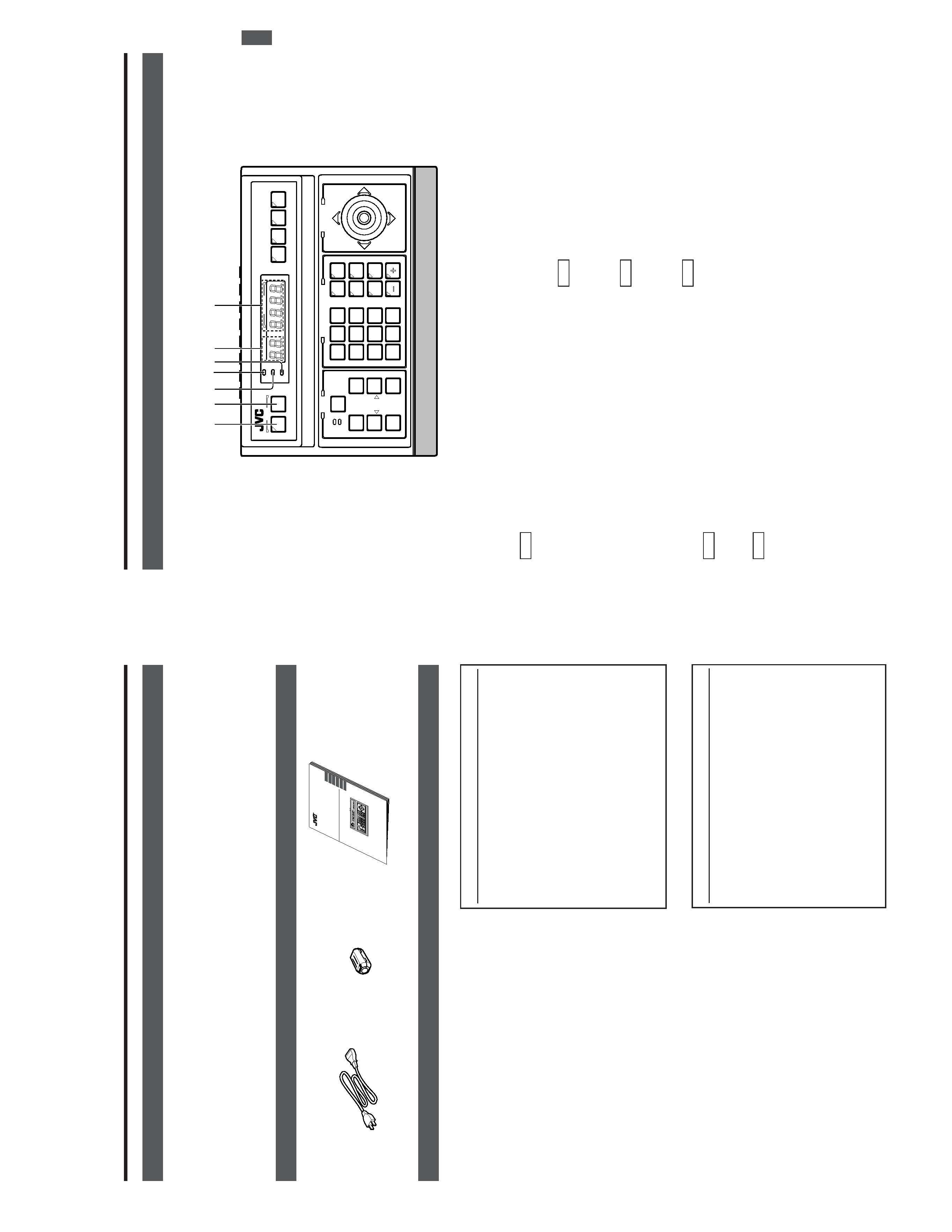
1
[MENU]
b
utton
(with
an
indicator)
When
this
button
is
pressed,
the
MONIT
OR
OUTPUT
1
,
on
the
rear
panel
outputs
a
menu
screen
and
the
indi-
cator
with
this
button
lights
up.
REF
.:
"MENU
SCREEN
SETUP"
on
page
25.
2
[SET]
b
utton
While
a
normal
screen
is
displayed
(i.e.
when
a
menu
screen
is
not
displayed),
pressing
and
holding
this
button
for
more
than
3
seconds
generates
a
short
beep,
lights
up
the
KEY
LOCK
indicator
5
and
then
puts
the
unit
to
the
KEY
LOCK
status.
In
the
KEY
LOCK
status,
all
buttons
as
well
as
the
P
AN/
TIL
T
control
lever
#
on
the
control
panel
are
inactive.
To
release
the
KEY
LOCK
status,
press
and
hold
the
SET
button
again
for
more
than
3
seconds.
While
a
menu
screen
is
displayed,
this
button
is
used
to
display
a
menu
in
a
lower
hierarchy
level
or
to
enter
a
set-
ting.
REF
.:
"MENU
SCREEN
SETUP"
on
page
25.
3
[ALARM]
indicator
This
indicator
blinks
when
an
alarm
signal
is
input.
REF
.:
"ALARM
OPERA
TION"
on
page
17.
4
[PO
WER]
indicator
This
indicator
lights
up
when
the
POWER
switch
fi
on
the
rear
panel
is
set
to
ON.
5
[KEY
LOCK]
indicator
This
indicator
lights
up
when
the
unit
is
in
the
KEY
LOCK
status.
REF
.
:"
2
[SET]
button"
for
the
KEY
LOCK
status
setting.
6
[CAMERA]
displa
y
Shows
the
camera
number
of
the
camera
signals
output
from
the
MONIT
OR
OUTPUT
1
connector
,
.
REF
.:
"CAMERA
SELECTION"
on
page
10.
7
[POSITION]
displa
y
Shows
the
position
number
of
the
camera
signals
output
from
the
MONIT
OR
OUTPUT
1
connector
,
.
REF
.:
"POSITION
SELECTION"
on
page
1
1.
1.
INTRODUCTION
CONTR
OLS,
CONNECT
ORS
AND
INDICA
T
ORS
[Contr
ol
P
anel]
SETUPSETUP
MENUMENU
SETSET
SPEEDSPEED
IRIS
AF
FOCUS
ZOOM
OPENOPEN
FAR
TELETELE
CLEARCLEAR
/HOME/HOME
7
4
1
8
0
5
2
9
6
3
ENTERENTER
AUTO
PANPAN
OPTIONOPTION
1
OPTIONOPTION
2
CAMERACAMERA
POSI-POSI-
TIONTION
AUTOAUTO
PATROL
CLOSECLOSE
NEARNEAR
WIDEWIDE
AUTOAUTO
F-1
F-2
F-3F-3
PAN/TILT
LENS
CAMERA/POSITION
CAMERACAMERA
POSITIONPOSITION
REMOTE
CONTROL
UNIT
RM-P2580
ALARM
PO
WER
KEY
LOCK
1
2
4
35
6
7
E-6
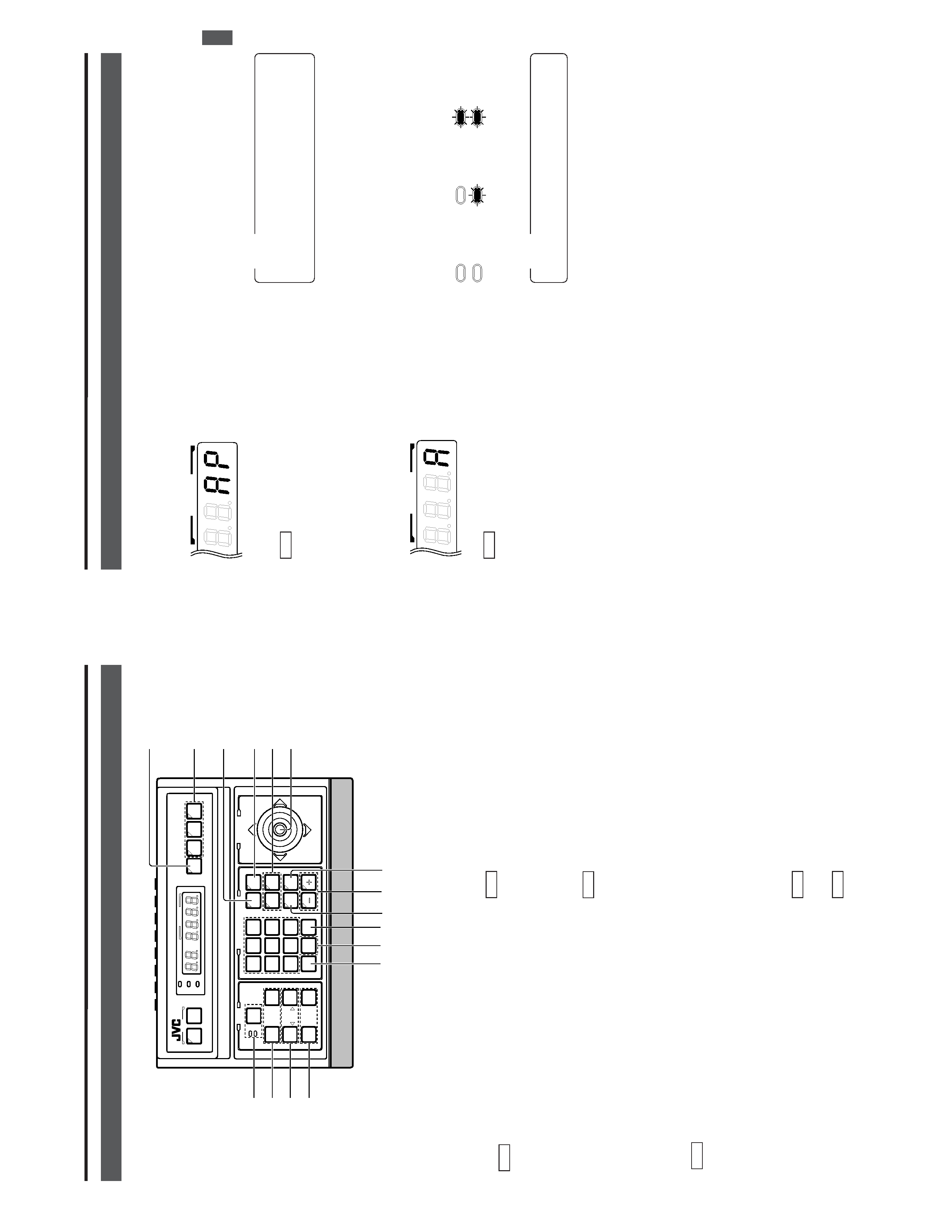
!
[POSITION]
b
utton
Press
when
selecting
one
of
the
position
numbers
preset
for
the
camera.
To
select
a
position,
use
the
following
buttons:
POSITION
button
!
Numeric
key
buttons
*
EN-
TER
button
&
.
REF
.:
"POSITION
SELECTION"
on
page
1
1.
@
[OPTION
1,
2]
These
buttons
are
not
used
for
the
present.
Do
not
touch
them.
#
[P
AN/TIL
T]
contr
ol
le
ver
Operate
the
lever
to
pan
(swing
horizontally)
or
tilt
(swing
vertically)
the
rotary
turret
of
a
camera.
8
(Up)
:
T
ilt
the
lever
in
this
direction
to
tilt
the
rotary
turret
upward.
9
(Down)
:
T
ilt
the
lever
in
this
direction
to
tilt
the
rotary
turret
downward.
:
(Right)
:
T
ilt
the
lever
in
this
direction
to
pan
the
rotary
turret
toward
the
right.
;
(Left)
:
T
ilt
the
lever
in
this
direction
to
pan
the
rotary
turret
toward
the
left.
REF
.:
"MANUAL
OPERA
TION"
on
page
12.
While
a
menu
screen
is
displayed,
this
lever
is
used
to
select
or
to
set
an
item.
REF
.:
"MENU
OPERA
TION
METHOD"
on
page
26.
1.
INTRODUCTION
CONTR
OLS,
CONNECT
ORS
AND
INDICA
T
ORS
(Continued)
SETUPSETUP
MENUMENU
SETSET
SPEEDSPEED
IRIS
AF
FOCUS
ZOOM
OPENOPEN
FARFAR
TELETELE
CLEARCLEAR
/HOME/HOME
7
4
1
8
0
5
2
9
6
3
ENTERENTER
AUTOAUTO
PAN
OPTIONOPTION
1
OPTIONOPTION
2
CAMERACAMERA
POSI-POSI-
TIONTION
AUTOAUTO
PATROLPATROL
CLOSECLOSE
NEARNEAR
WIDEWIDE
AUTOAUTO
F-1F-1
F-2F-2
F-3F-3
PAN/TILT
LENS
CAMERA/POSITION
CAMERACAMERA
POSITIONPOSITION
REMOTE
CONTROL
UNIT
REMOTE
CONTROL
UNIT
RM-P2580
ALARM
PO
WER
KEY
LOCK
*&
(
¤
/
)
<
$
^
%
9
@
#
0
8
!
0
[CAMERA]
b
utton
Press
when
selecting
a
camera.
To
select
a
camera,
use
the
following
buttons:
CAMERA
button
0
Numeric
key
buttons
*
ENTER
button
&
.
REF
.
:"CAMERA
SELECTION"
on
page
10.
8
[A
UT
O]
b
utton
When
this
button
is
pressed,
the
unit
enters
the
AUT
O
SE-
QUENCE
mode,
in
which
the
indicator
lights
up
and
the
MONIT
OR
OUTPUT
1
connector
,
on
the
rear
panel
out-
put
the
camera
video
signals
according
to
automatic
switch-
ing.
REF
.
:"AUT
O
SEQUENCE
OPERA
TION"
on
page
13.
9
[F1,
F2,
F3]
Function
b
uttons
E
model
These
buttons
are
not
used
for
the
present.
Do
not
touch
them.
U
model
These
buttons
are
valid
only
when
SW
-D7000/SW
-D8000
frame
switchers
are
being
used.
When
this
unit
is
operated
in
the
B
mode,
these
buttons
can
control
certain
functions
of
the
specific
frame
switcher
model
connected
to
this
unit.
The
RS-232C
control
is
in-
volved
in
this
control
operation.
For
details,
please
consult
your
dealer
or
JVC-authorized
service
agent.
REF
.:
"APPLIED
SYSTEM
(B
MODE)"
on
page
22.
F1
:
Single-screen
select
s
witc
h
Press
this
button
to
output
a
single-screen
video
from
the
frame
switcher
.
The
camera
number
can
be
selected
using
the
numeric
keypad
,etc.
F2
:
Split-screen
select
s
witc
h
Press
this
button
to
output
a
split-screen
video
from
the
frame
switcher
.
F3:
LIVE/PLA
Y
s
witc
h
Press
this
button
to
switch
between
the
playback
video
of
a
time-lapse
VCR
and
the
camera
video.
E-7
The
AUT
O
P
A
TROL
function
can
be
set
on
a
per-camera
basis.
REF
.:
"AUT
O
P
A
TROL
OPERA
TION"
on
page
15.
%
[,
+]
Negative
and
positive
b
uttons
Press
button
to
decrease
or
increase
the
camera
or
posi-
tion
number
.
^
[A
UT
O
P
AN]
b
utton
Press
this
button
to
rotate
or
swing
a
camera
between
pre-
set
positions
at
a
preset
time
interval.
1.
INTRODUCTION
CONTR
OLS,
CONNECT
ORS
AND
INDICA
T
ORS
(Continued)
$
[A
UT
O
P
A
TR
OL]
b
utton
Press
this
button
to
switch
the
camera
positions
automati-
cally
in
a
preset
order
and
at
preset
time
intervals.
The
POSITION
display
be-
comes
as
shown
on
the
left
during
AUT
O
P
A
TROL.
REF
.:
"AUT
O
P
AN
OPERA
TION"
on
page
14.
&
[ENTER]
b
utton
Press
to
enter
a
figure
input
using
the
numeric
key
buttons
*
.
*
[1
to
0/HOME]
Numeric
ke
y
b
uttons
Use
these
buttons
to
choose
a
camera
or
position
number
.
(
[CLEAR]
b
utton
Press
to
clear
an
input
figure
before
it
is
entered
by
press-
ing
the
ENTER
button.
)
[ZOOM
WIDE,
TELE]
ZOOM
contr
ol
b
uttons
Press
and
hold
to
control
the
ZOOM
operation
of
the
cam-
era
lens.
WIDE:
Zooms
out
and
widens
the
image.
TELE:
Zooms
in
and
narrows
the
image.
/
[FOCUS
NEAR,
F
AR]
FOCUS
contr
ol
b
uttons
Press
and
hold
to
control
the
FOCUS
operation
of
the
cam-
era
lens.
NEAR
:
Brings
a
near
object
in
focus.
FA
R
:Brings
a
distant
object
in
focus.
AF
(AUT
O
FOCUS)
When
the
NEAR
and
F
AR
buttons
are
simultaneously
pressed
and
held
for
about
1
second,
a
short
beep
is
gen-
erated
and
the
object
is
automatically
brought
into
focus.
The
POSITION
display
be-
comes
as
shown
on
the
left
during
AUT
O
P
AN.
¤
[IRIS
CLOSE,
OPEN]
Iris
contr
ol
b
utton.
Press
and
hold
to
control
the
lens
iris.
CLOSE
:Closes
the
lens
iris.
OPEN
:Opens
the
lens
iris.
<
[SPEED]
Speed
b
utton
and
indicator
s
Press
to
set
the
speed
of
the
ZOOM
and
FOCUS
control
operations.
Each
press
of
the
button
changes
the
operation
speed.
POSITION
POSITION
:Low
speed
:Medium
speed
:High
speed
NO
TE
When
the
power
is
turned
on,
the
operation
speed
is
medium.
NO
TE
If
the
camera
being
selected
does
not
incorporate
the
AUT
O
FOCUS
function,
this
function
is
not
available
even
when
the
short
beep
is
generated.
Be
sure
to
use
this
function
while
observing
the
monitor
screen.
E-8
>
[A
C
`
INPUT]
A
C
po
wer
input
connector
E
model
Connect
to
a
conventional
100
to
240V
AC
power
supply
using
the
provided
power
cord.
U
model
Connect
to
a
conventional
120
V
AC
power
supply
using
the
provided
power
cord.
fi
[PO
WER]
s
witc
h
T
urns
the
power
of
the
unit
ON
and
OFF
.When
this
switch
is
set
to
ON,
the
POWER
indicator
4
on
the
front
panel
lights
up.
fl
[T
O
CAMERA]
Camera
contr
ol
signal
connector
s
Connection
terminals
for
use
in
controlling
the
cameras.
The
control
communications
use
the
multi-drop,
full-du-
plex
communication
system
(RS-485).
REF
.
:"REAR
P
ANEL
CONNECT
ORS
(T
O
CAMERA)"
on
page
23.
[D
A
T
A
I/O]
Data
signal
input/output
terminals
Connection
terminals
for
use
by
the
alarm
input/output
and
select
output
signals.
Connect
the
CAMERA
SW
terminal
to
a
time-lapse
VCR.
REF
.:
"REAR
P
ANEL
CONNECT
ORS
(DA
T
A
I/O)"
on
page
24.
[SERIAL-1]
External
e
xtension
connector
1
(D-sub
9-pin
male
connector)
Use
this
connector
when
connecting
an
external
compo-
nent
such
as
an
alarm
unit.
REF
.
:"REAR
P
ANEL
CONNECT
ORS
(SERIAL-1,
-2)"
on
page
23.
Contact
your
JVC
sales
agent
for
details.
·
[SERIAL-2]
External
e
xtension
connector
2
(D-sub
9-pin
male
connector)
E
model
These
buttons
are
not
used
for
the
present.
Do
not
touch
them.
U
model
REF
.
:"REAR
P
ANEL
CONNECT
ORS
(SERIAL-1,
-2)"
on
page
23.
,
[MONIT
OR
OUTPUT
1]
Video
signal
output
con-
nector
1
Outputs
the
video
signal
selected
with
this
unit.
Connect
to
the
video
monitor
,etc.
This
connector
also
outputs
the
video
signal,
which
car-
ries
the
on
screen
menu.
¡
[MONIT
OR
OUTPUT
2]
Video
signal
output
con-
nector
2
Connect
to
a
time-lapse
VCR,
etc.
The
camera
video
signal
output
from
this
connector
is
switched
according
to
the
switching
signal
input
at
the
CAMERA
SW
IN
terminal
.
When
this
unit
is
operated
in
the
B
mode
(
REF
.
:Page
21
):
This
connector
outputs
the
same
signal
as
the
MONIT
OR
OUTPUT
1
connector
,
.
TM
[VIDEO
INPUT]
Video
signal
input
connector
s
These
connectors
input
the
video
signals
from
the
cam-
eras.
When
this
unit
is
operated
in
the
B
mode,
apply
the
output
signal
from
a
frame
switcher
to
the
VIDEO
INPUT
1
con-
nector
.
REF
.
:"BASIC
SYSTEM"
on
page
19,
"APPLIED
SYSTEM"
on
page
21.
£
[VIDEO
OUTPUT]
Video
signal
output
connector
s
Each
of
these
connectors
outputs
the
video
signal
corre-
sponding
to
the
VIDEO
INPUT
connector
TM
above
it.
Connect
these
connectors
to
a
video
device
such
as
a
monitor
.
¢
DIP
s
witc
h
Used
to
switch
the
system
mode
or
the
standard
applied
to
the
SERIAL-1
and
-2
connectors.
REF
.
:"REAR
P
ANEL
CONNECT
ORS
(DIP
SWITCH)"
on
page
23.
1.
INTRODUCTION
CONTR
OLS,
CONNECT
ORS
AND
INDICA
T
ORS
(Continued)
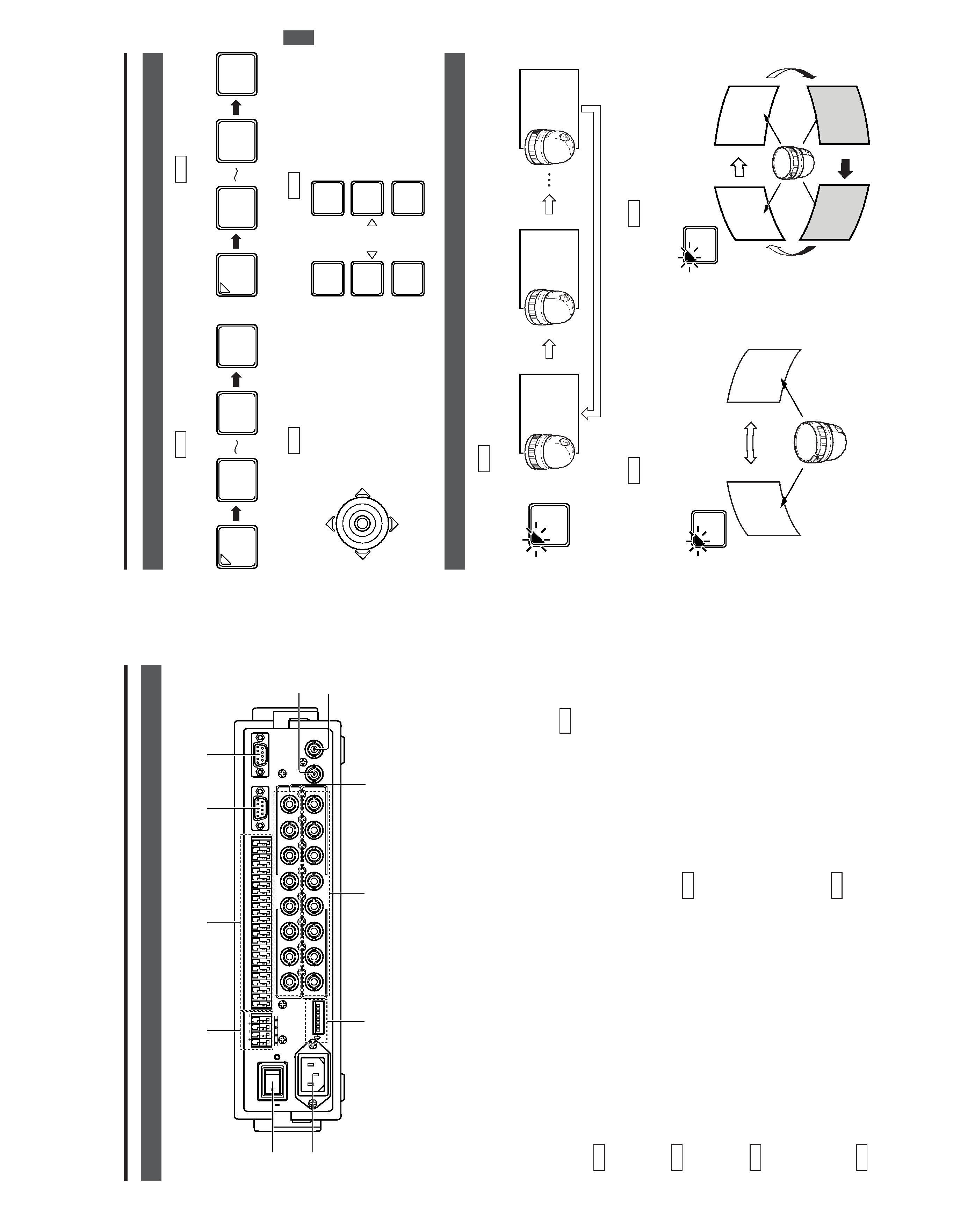
[Rear
P
anel]
1
TO
CAMERA
DATA
I
/
O
RXRX
+
RXRX
-
TXTX
+
TXTX
-
COMCOM
1
2
3
4
5
6
7
8
COMCOM
9/1
10/2
11/3
12/4
13/5
14/6
15/7
16/8
COMCOM
COMCOM
COMCOM
CAMERA
SW
UNIT ALARMALARM
AUTO
4
3
1
2
8
7
5
6
2
3
4
5
6
7
8
1
MONITOR OUTPUT
MONITOR
SERIAL-2
SERIAL-1
VIDEO
INPUT
VIDEO
OUTPUT
OUTPUT
2
1
ONON
2
3
4
5
6
7
8
POWER
OFF
ON
AC
INPUT
`
£
fl
°
>
fi
·
¢
,
¡
TM
°
E-9
2.
BASIC
OPERA
TIONS
Man
ual
Operation
Camera
Selection
(
REF
.
:Page
10)
Switching
to
the
selected
camera
video.
P
an/Tilt
Operation
(
REF
.
:
Page
12)
(TIL
T)
T
ilts
the
camera
up
and
down,
(P
AN)
Pans
the
camera
in
the
left
and
right
directions.
P
osition
Selection
(
REF
.
:
Page
1
1
)
Switching
the
camera
to
the
selected
video
position.
Operation
of
the
Camera
IRIS
(Brightness),
FOCUS
(focus-
ing)
and
ZOOM
(screen
size).
Lens
Operation
(
REF
.
:
Page
12)
A
utomatic
Operation
A
uto
Sequence
(
REF
.
:
Page
13)
The
scene
captured
by
cameras
1
to
8
is
automatically
switched
in
a
preset
time
interval.
A
uto
P
anning
(
REF
.
:
Page
14)
The
camera
moves
automatically
and
slowly
between
2
points
in
a
horizontal
direction.
A
uto
P
atr
ol
(
REF
.
:
Page
15)
Moves
the
camera
through
many
positions
in
a
high-speed
manner
.
1
8
ENTER
CAMERA
1
/HOME
0
ENTER
POSI-
TION
PAN/TILT
IRIS
AF
FOCUS
ZOOM
OPEN
FAR
TELE
CLOSE
NEAR
WIDE
Camera
1
scene
Camera
8
scene
Camera
2
scene
AUTO
Slowly
Stop positionscene
Start
position
scene
AUTO
PAN
High-speed
High-speed
High-speed
High-speed
Position
1
Position
2
Position
3
Position
4
AUTO
PATROL