INSTRUCTIONS
BEDIENUNGSANLEITUNG
MANUEL D'INSTRUCTIONS
(A)
REMOTE CONTROL UNIT
FERNBEDIENUNGSEINHEIT
COMMANDE A DISTANCE
RM-P2580
RM
P2580
REMOTE
CONTROL
UNIT
SETUP
MENU
MENU
SET
SET
SPEED
SPEED
IRIS
AF
FOCUS
ZOOM
OPEN
OPEN
FAR
FAR
TELE
TELE
CLEAR
CLEAR
/ALL
/ALL
7
4
1
8
0
5
2
9
6
3
ENTER
ENTER
AUTO
AUTO
PAN
PAN
HOME
HOME
FUNC-
FUNC-
TION
TION
CAMERA
POSI-
POSI-
TION
TION
PRESET
SEQ
SEQ
CLOSE
CLOSE
NEAR
NEAR
WIDE
WIDE
AUTO
AUTO
F-1
F-2
F-3
PAN/TILT
LENS
CAMERA/POSITION
ALARM
ALARM
CAMERA
CAMERA
POSITION
POSITION
REMOTE CONTROL UNIT
RM-P2000
KEY LOCK
KEY LOCK
LWT0111-001A
R
SETUP
MENU
MENU
SET
SET
SPEED
SPEED
IRIS
AF
FOCUS
ZOOM
OPEN
OPEN
FAR
FAR
TELE
TELE
CLEAR
CLEAR
/HOME
/HOME
7
4
1
8
0
5
2
9
6
3
ENTER
ENTER
AUTO
AUTO
PAN
PAN
OPTION
OPTION
1
OPTION
OPTION
2
CAMERA
CAMERA
POSI-
POSI-
TION
TION
AUTO
AUTO
PATROL
PATROL
CLOSE
CLOSE
NEAR
NEAR
WIDE
WIDE
AUTO
AUTO
F-1
F-1
F-2
F-2
F-3
F-3
PAN/TILT
LENS
CAMERA/POSITION
ALARM
ALARM
PO
POWER
WER
CAMERA
CAMERA
POSITION
POSITION
REMOTE CONTROL UNIT
RM-P2580
KEY LOCK
KEY LOCK
INTRODUCTION
BASIC OPERATIONS
APPLIED OPERATIONS
OTHER
CONNECTIONS
MENU SCREEN SETUPS
Untitled-2
03.4.22, 11:12 AM
3
E-2
Changes or modifications not approved by JVC could void
the user's authority to operate the equipment.
This unit is designed for professional use only.
SAFETY PRECAUTIONS
WARNING:
TO PREVENT FIRE OR SHOCK HAZARD, DO
NOT EXPOSE THIS APPLIANCE TO RAIN OR
MOISTURE.
IMPORTANT
The wires in this mains lead are coloured in accordance
with the following code:
GREEN - AND - YELLOW:
EARTH
BLUE:
NEUTRAL
BROWN:
LIVE
As the colours of the wires in the mains lead of this appara-
tus may not correspond with the coloured markings identi-
fying the terminals in your plug. proceed as follows.
The wire which is coloured GREEN-AND-YELLOW must
be connected to the terminal in the plug which is marked
with the letter E or by the safety earth symbol
or col-
oured GREEN or GREEN-AND -YELLOW. The wire which
is coloured BLUE must be connected to the terminal which
is marked with the letter N or which is coloured BLACK.
The wire which is coloured BROWN must be connected
to the terminal which is marked with the letter L or coloured
RED.
WARNINGTHIS APPARATUS
MUST BE EARTHED
RM-P2580E-E
03.4.22, 10:20 AM
2

E-3
1. INTRODUCTION
CONTENTS .......................................................................................................................................... 3
FEATURES ........................................................................................................................................... 4
ACCESSORIES ................................................................................................................................... 4
PRECAUTIONS FOR PROPER OPERATION ..................................................................................... 4
CONTROLS, CONNECTORS AND INDICATORS ............................................................................... 5
2. BASIC OPERATIONS
CAMERA SELECTION ....................................................................................................................... 10
POSITION SELECTION ..................................................................................................................... 11
MANUAL OPERATION ....................................................................................................................... 12
AUTO SEQUENCE OPERATION ....................................................................................................... 13
AUTO PAN OPERATION .................................................................................................................... 14
AUTO PATROL OPERATION.............................................................................................................. 15
KEY LOCK (PREVENTION OF OPERATION MISTAKE)................................................................... 16
3. APPLIED OPERATIONS
ALARM OPERATION ......................................................................................................................... 17
DATA OUTPUT ................................................................................................................................... 18
CAMERA SWITCHING OPERATION ................................................................................................. 18
4. CONNECTIONS
BASIC SYSTEM (A MODE) ............................................................................................................... 19
APPLIED SYSTEM (B MODE) ........................................................................................................... 21
REAR PANEL CONNECTORS .......................................................................................................... 23
5. MENU SCREEN SETUPS
FLOW OF MENUS ............................................................................................................................. 25
MENU OPERATION ........................................................................................................................... 26
SETUP SCREEN (MAIN MENU)
POSITION SETUP SCREEN .......................................................................................................... 27
CAMERA SCREEN ......................................................................................................................... 28
CONTROL UNIT SCREEN .............................................................................................................28
OPTION SCREEN ..................................................................................................................... 29
DATA I/O SCREEN .................................................................................................................... 30
ALARM SCREEN ...................................................................................................................... 32
AUTO SEQUENCE SCREEN .................................................................................................... 32
6. OTHER
TROUBLESHOOTING ........................................................................................................................ 33
SPECIFICATIONS .............................................................................................................................. 34
1. INTRODUCTION
CONTENTS
Thank you for purchasing the JVC RM-P2580.
These instructions are for the RM-P2580E.
RM-P2580E-E
03.4.22, 10:20 AM
3
E-4
Presetting of up to 100 positions (including the home positions) each, for up to 8 combination cameras.
Built-in PAN, TILT and ZOOM control for up to 8 cameras.
RS-485 connection system enables cascaded connection of cameras.
Built-in sequential switcher.
Alarm input terminals.
Data I/O terminals for interlocked operation with external peripherals.
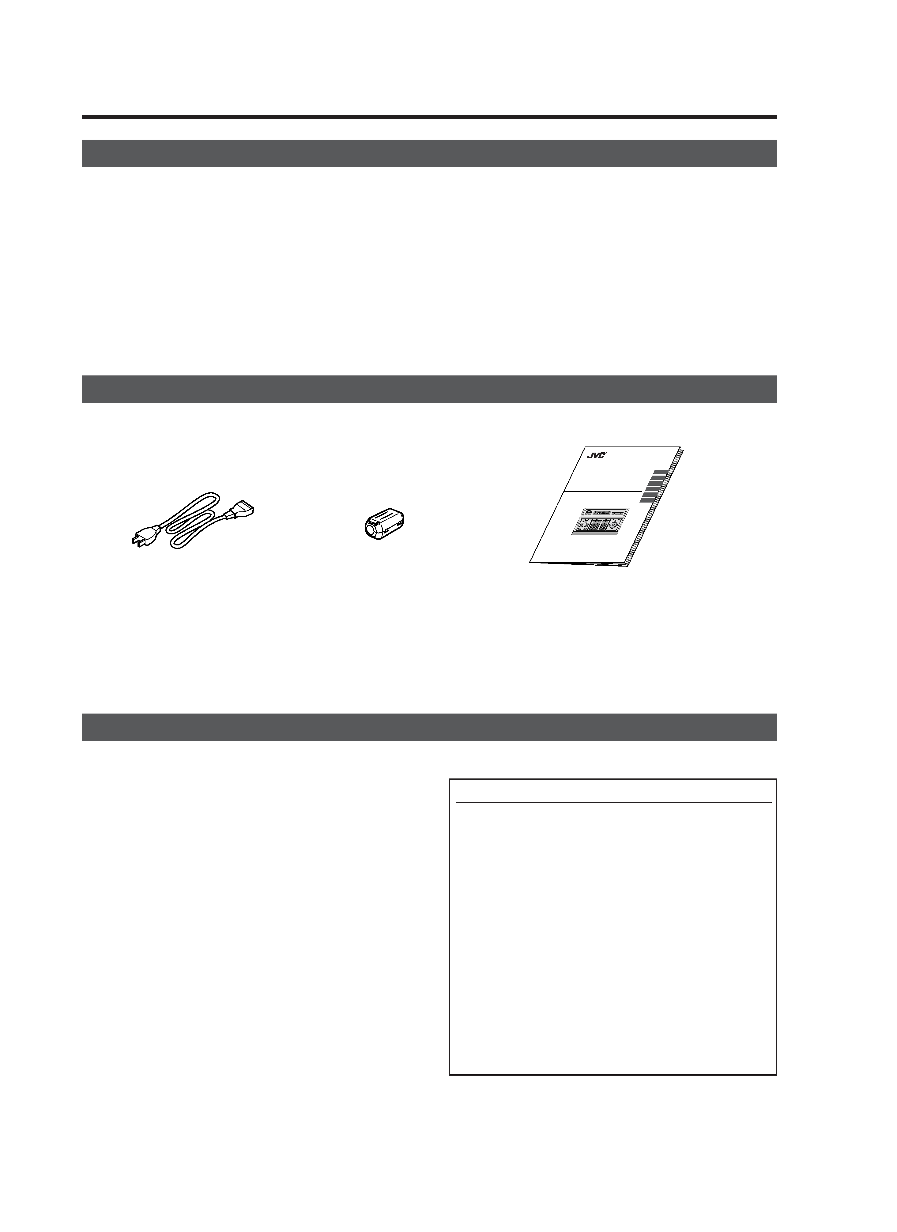
ACCESSORIES
1. INTRODUCTION
FEATURES
Precautions for the PRESET SEQUENCE and AUTO PAN Operations
The life-span of the PRESET SEQUENCE and AUTO PAN
functions is dependent on which camera model is used in
combination with this unit.
When using the TK-C655 and TK-C676 cameras, the guar-
anteed zoom lens operation count is 200,000 times. If the
zoom lens operation is used often, the life-span of the PRE-
SET SEQUENCE and AUTO PAN functions may be much
less than expected.
(Example) Assuming that a ZOOM operation is performed
every minute and the camera is used 24 hours
a day:
200,000 x 2 (times) ÷ 60 (minutes) ÷ 24 (hours) = 277 (days)
Total operations count
Daily operating hours
For other camera models, please refer to the Handling &
Installation Instructions manuals of the camera in use.
Do not install the unit in a place subject to direct sunlight,
excessive moisture, dust, or vibrations where ventilation is
poor.
Be careful of strong radio waves and magnetism:
If the unit is near a source of strong magnetism, such as a
radio or TV transmission antenna, power transformer or
motor, the video signal may be subject to interference.
Always use the power cord provided with or specified for
this unit.
CLEAN EXTERIOR
Wipe gently with a soft cloth.
Put cloth in diluted mild soap and wring it well to wipe off
heavy dirt. Then wipe again with a dry cloth.
To save energy, be sure to turn off the system when not in
use.
PRECAUTIONS FOR PROPER OPERATION
Power cord (2 m)
Ferrite Core
Instructions (this manual)
INSTRUCTIONS
BEDIENUNGSANLEITUNG
MANUEL D'INSTRUCTIONS
REMOTE CONTROL UNIT
FERNBEDIENUNGSEINHEIT
COMMANDE A DISTANCE
RM-P2580
SETUP
MENU
MENU
SET
SET
SPEED
SPEED
IRIS
AF
FOCUS
ZOOM
OPEN
OPEN
FAR
FAR
TELE
TELE
CLEAR
CLEAR
/ALL
/ALL
7
4
1
8
0
5
2
9
6
3
ENTER
ENTER
AUTO
AUTO
PAN
PAN
HOME
HOME
FUNC-
FUNC-
TION
TION
CAMERA
CAMERA
POSI-
POSI-
TION
TION
PRESET
PRESET
SEQ
SEQ
CLOSE
CLOSE
NEAR
NEAR
WIDE
WIDE
AUTO
AUTO
F-1
F-1
F-2
F-2
F-3
F-3
PAN/TILT
LENS
CAMERA/POSITION
ALARM
ALARM
CAMERA
CAMERA
POSITION
POSITION
REMOTE CONTROL UNIT
RM-P2000
KEY LOCK
KEY LOCK
SC96859-001
R
SETUP
MENU
MENU
SET
SET
SPEED
SPEED
IRIS
AF
FOCUS
ZOOM
OPEN
OPEN
FAR
FAR
TELE
TELE
CLEAR
CLEAR
/HOME
/HOME
7
4
1
8
0
5
2
9
6
3
ENTER
ENTER
AUTO
AUTO
PAN
PAN
OPTION
OPTION
1
OPTION
OPTION
2
CAMERA
CAMERA
POSI-
POSI-
TION
TION
AUTO
AUTO
PATROL
PATROL
CLOSE
CLOSE
NEAR
NEAR
WIDE
WIDE
AUTO
AUTO
F-1
F-1
F-2
F-2
F-3
F-3
PAN/TILT
LENS
CAMERA/POSITION
ALARM
ALARM
PO
POWER
WER
CAMERA
CAMERA
POSITION
POSITION
REMOTE CONTROL UNIT
RM-P2580
KEY LOCK
KEY LOCK
INTRODUCTION
BASIC OPERATIONS
APPLIED OPERATIONS
OTHER
CONNECTIONS
MENU SCREEN SETUPS
RM-P2580E-E
03.4.22, 10:20 AM
4
E-5
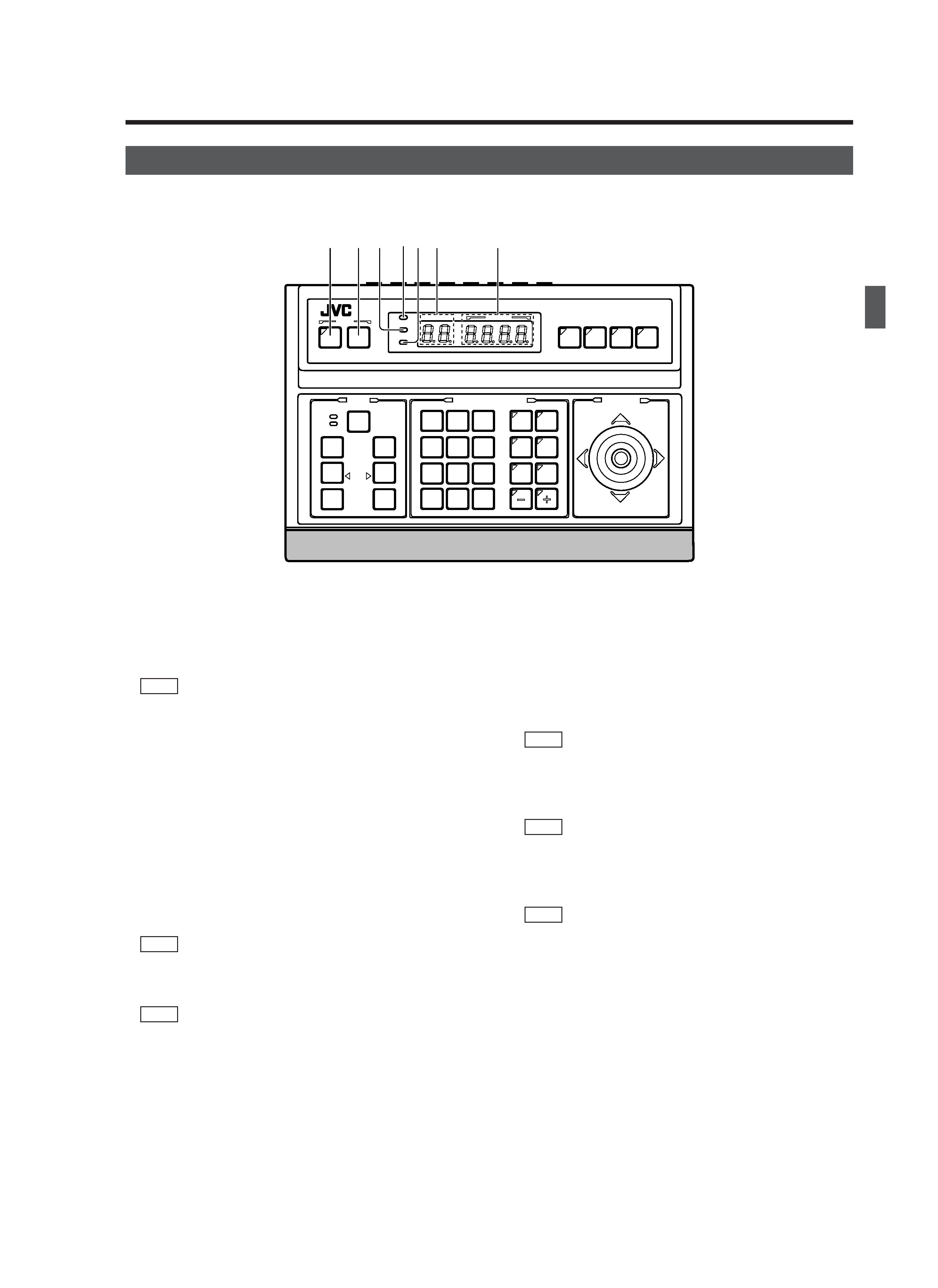
1 [MENU] button (with an indicator)
When this button is pressed, the MONITOR OUTPUT 1
, on the rear panel outputs a menu screen and the indi-
cator with this button lights up.
REF. : "MENU SCREEN SETUP" on page 25.
2 [SET] button
While a normal screen is displayed (i.e. when a menu
screen is not displayed), pressing and holding this button
for more than 3 seconds generates a short beep, lights up
the KEY LOCK indicator
5 and then puts the unit to the
KEY LOCK status.
In the KEY LOCK status, all buttons as well as the PAN/
TILT control lever
# on the control panel are inactive.
To release the KEY LOCK status, press and hold the SET
button again for more than 3 seconds.
While a menu screen is displayed, this button is used to
display a menu in a lower hierarchy level or to enter a set-
ting.
REF. : "MENU SCREEN SETUP" on page 25.
3 [ALARM] indicator
This indicator blinks when an alarm signal is input.
REF. : "ALARM OPERATION" on page 17.
4 [POWER] indicator
This indicator lights up when the POWER switch
fi on the
rear panel is set to ON.
5 [KEY LOCK] indicator
This indicator lights up when the unit is in the KEY LOCK
status.
REF. : "
2 [SET] button" for the KEY LOCK status setting.
6 [CAMERA] display
Shows the camera number of the camera signals output
from the MONITOR OUTPUT 1 connector
,.
REF. : "CAMERA SELECTION" on page 10.
7 [POSITION] display
Shows the position number of the camera signals output
from the MONITOR OUTPUT 1 connector
,.
REF. : "POSITION SELECTION" on page 11.
1. INTRODUCTION
CONTROLS, CONNECTORS AND INDICATORS
[Control Panel]
SETUP
SETUP
MENU
MENU
SET
SET
SPEED
SPEED
IRIS
IRIS
AF
AF
FOCUS
FOCUS
ZOOM
ZOOM
OPEN
OPEN
FAR
FAR
TELE
TELE
CLEAR
CLEAR
/HOME
/HOME
7
4
1
8
0
5
2
9
6
3
ENTER
ENTER
AUTO
AUTO
PAN
PAN
OPTION
OPTION
1
OPTION
OPTION
2
CAMERA
CAMERA
POSI-
POSI-
TION
TION
AUTO
AUTO
PATROL
PATROL
CLOSE
CLOSE
NEAR
NEAR
WIDE
WIDE
AUTO
AUTO
F-1
F-1
F-2
F-2
F-3
F-3
PAN/TILT
LENS
CAMERA/POSITION
CAMERA/POSITION
CAMERA
CAMERA
POSITION
POSITION
REMOTE CONTROL UNIT
REMOTE CONTROL UNIT
RM-P2580
RM-P2580
ALARM
POWER
KEY LOCK
1 2
4
35 6
7
RM-P2580E-E
03.4.22, 10:20 AM
5