E-33
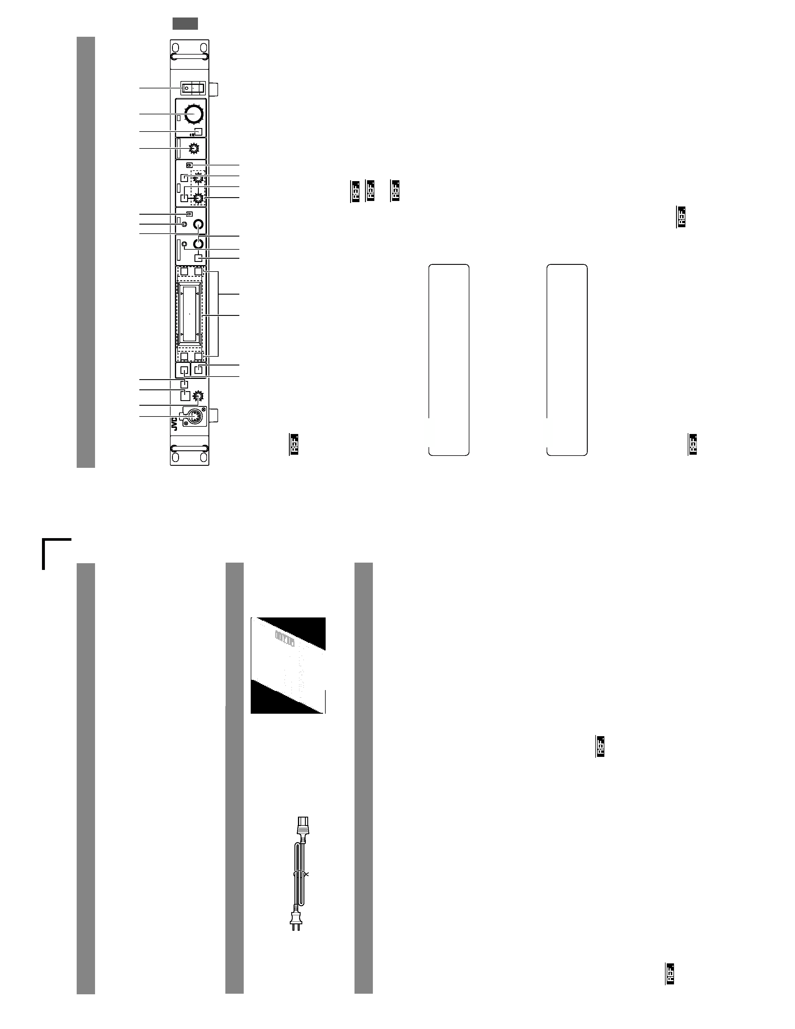
RM-P210
SC961003(E)
R
This
instruction
book
is
made
from
100%
recycled
paper
.
INTRODUCTION
CONNECTION
PREP
ARA
TIONS
AND
MAIN
FUNCTIONS
GENERAL
CAMERA
ADJUSTMENTS
MENU
OPERA
TION
CALL
TALLY
INTERCOM
LEVEL
FULL
AUTO
F1
SHUTTER
GAIN
F2
F3
MENU/SHUTTER
GAIN
PAINT
AUTO
B
R
W.BAL
AUTO
MANU
WHITE
MASTER
BLACK
POWER
I
O
IRIS
STEP
SHUTTER
MENU
PUSH-ON
DOWN
UP
VARIABLE
PUSH-ON
HIGH
LOW
B
A
PRESET
CLOSE
O
PEN
MID
DOWN
U
P
F4
BARS
REMOTE
CONTROL
UNIT
RM-P210
REMOTE
CONTROL
UNIT
FERNBEDIENUNGSEINHEIT
COMMANDE
A
DISTANCE
INSTRUCTIONS
BEDIENUNGSANLEITUNG
MANUEL
D'NSTRUCTIONS
E
CALL
TALLY
INTERCOM
LEVEL
FULL
AUTO
F1
SHUTTER
GAIN
F2
F3
MENU/SHUTTER
GAIN
PAINT
AUTO
B
R
W.BAL
AUTO
MANU
WHITE
MASTER
BLACK
POWER
I
O
IRIS
STEP
SHUTTER
MENU
PUSH-ON
DOWN
U
P
VARIABLE
PUSH-ON
HIGH
LOW
B
A
PRESET
CLOSE
O
PEN
MID
DOWN
UP
F4
BARS
REMOTE
CONTROL
UNIT
RM-P210
U
INSTRUCTIONS
REMOTE
CONTROL
UNIT
RM-P210
SC961002(U)
R
For
Customer
Use:
Enter
below
the
Model
No.
and
Serial
No.
which
are
located
on
the
bodie.
Retain
this
information
for
future
reference.
Model
No.
RM-P210
Serial
No.
This
instruction
book
is
made
from
100%
recycled
paper
.
INTRODUCTION
CONNECTION
PREP
ARA
TIONS
AND
MAIN
FUNCTIONS
GENERAL
CAMERA
ADJUSTMENTS
MENU
OPERA
TION
E-2
INTRODUCTION
INTR
ODUCTION
F
eatures
...........................................................................
3
Pro
vided
Accessor
ies
and
Documents
............................
3
Precautions
f
o
rProper
Use
.............................................
3
Controls
,Connectors
and
Indicators
...............................
4
F
ront
panel
...................................................................
4
Rear
panel
....................................................................
6
CONNECTION
Example
of
Basic
Connection
..........................................
7
Example
of
RM-P210
(Connection
of
2
units)
.................
8
Camer
a
Setup
..................................................................
9
T
u
rn
ing
the
P
o
w
e
rON
....................................................
10
PREP
ARA
TIONS
AND
MAIN
FUNCTIONS
Camer
a
Cab
le
Length
Setup
.........................................
11
Adjustments
f
o
rGenloc
k
Operation
...............................
12
Intercom
.........................................................................
13
Camer
a
Oper
ator
Call
....................................................
13
T
a
lly
Input
.......................................................................
13
Function
K
e
ys
................................................................
14
CAMERA
ADJUSTMENTS
Shutter
Speed
Adjustment
.............................................
15
Gain
Adjustment
............................................................
15
Ir
is
Adjustment
...............................................................
16
White
Balance
Adjustment
.............................................
17
MENU
OPERA
TION
Flo
w
of
Menus
...............................................................
18
Men
u
Setup
Method
......................................................
19
GENLOCK
Men
u
...........................................................
20
CABLE
Men
u
.................................................................
20
FILE
Men
u
.....................................................................
21
PR
OCESS
Menu
...........................................................
22
OPERA
TION
Men
u
........................................................
24
LCD
MODE
Men
u
..........................................................
25
SYSTEM
RESET
Men
u
.................................................
26
GENERAL
W
a
rn
ing
Messages
........................................................
27
Error
Messages
.............................................................
27
Functions
A
v
ailab
le
Depending
on
Camer
a
Models
......
28
T
roub
leshooting
.............................................................
29
Specifications
.................................................................
30
Contents
Changes
or
modifications
not
appro
v
ed
b
y
JVC
could
v
o
id
the
user's
author
ity
to
operate
the
equipment.
This
unit
is
designed
f
or
prof
essional
use
only
.
SAFETY
PRECAUTIONS
W
ARNING:
T
O
PREVENT
FIRE
OR
SHOCK
HAZARD
,D
O
NO
T
EXPOSE
THIS
APPLIANCE
T
O
RAIN
OR
MOISTURE.
IMPOR
T
ANT
The
wires
in
this
mains
lead
are
coloured
in
accordance
with
the
f
o
llo
wing
code:
GREEN
-
AND
-
YELLO
W:
EAR
TH
BLUE:
NEUTRAL
BR
O
W
N:
LIVE
As
the
colours
of
the
wires
in
the
mains
lead
of
this
appar
a-
tus
ma
y
not
correspond
with
the
coloured
mar
kings
identi-
fying
the
ter
m
inals
in
y
our
plug.
proceed
as
f
o
llo
ws
.
The
wire
which
is
coloured
GREEN-AND-YELLO
W
must
be
connected
to
the
ter
minal
in
the
plug
which
is
mar
ke
d
with
the
letter
E
or
b
y
the
saf
ety
ear
th
symbol
or
col-
o
u
re
d
GREEN
or
GREEN-AND
-YELLO
W
.The
wire
which
is
coloured
BLUE
m
ust
be
connected
to
the
ter
minal
which
is
mar
k
ed
with
the
letter
N
or
which
is
coloured
BLA
CK.
The
wire
which
is
coloured
BR
O
W
N
m
u
st
be
connected
to
the
ter
m
inal
which
is
mar
k
ed
with
the
letter
L
or
col-
oured
RED
.
W
ARNINGTHIS
APP
ARA
TUS
MUST
BE
EAR
THED
Thank
y
ou
f
o
rpurchasing
this
JVC
product.
Bef
ore
oper
ating
this
unit,
please
read
the
instr
uctions
care-
fully
to
ensure
the
best
possib
le
perf
o
rmance
.
These
instr
uctions
are
f
or
RM-P210E.
This
equipment
is
in
conf
or
mity
with
the
pro
visions
and
protection
requirements
of
the
corresponding
European
Directiv
es
.This
equipment
is
designed
f
or
prof
essional
video
appliances
and
can
be
used
in
the
f
ollo
wing
environments:
·residential
area
(in
houses)
or
r
ur
al
area
·commercial
and
light
industr
y;
e
.g.
offices
or
theatres
·urban
outdoors
In
order
to
k
eep
the
best
perf
or
mance
and
fur
ther
more
f
o
relectromagnetic
compatibility
w
e
recommend
to
use
cab
les
not
e
x
ceed-
ing
the
f
o
llo
wing
length:
P
o
rt
Cab
le
Lenght
CAMERA
CABLE
Exclusiv
e
Cab
le
100
meters
A
C
INPUT
A
C
P
o
w
er
Cab
le
2
meters
COMPOSITE
VIDEO
Coaxial
Cab
le
10
meters
Y/C
OUTPUT
Exclusiv
e
Cab
le
5
meters
B/B-Y
OUTPUT
Coaxial
Cab
le
10
meters
G/Y
OUTPUT
Coaxial
Cab
le
10
meters
P
o
rt
Cab
le
Lenght
R/R-Y
OUTPUT
Coaxial
Cab
le
10
meters
GENLOCK
INPUT
Coaxial
Cab
le
10
meters
A
UX
VIDEO
INPUT
Coaxial
Cab
le
10
meters
INTERCOM
J
A
CK
Cab
le
of
Intercom
2
meters
INTERCOM
(H,
C
,G)
Single
wire
5
meters
T
ALL
Y
Single
wire
5
meters
·
The
inr
ush
current
of
this
appar
atus
is
3.1
amperes
.
Caution
:
Where
there
are
strong
electromagnetic
w
a
ves
or
magnetism,
for
e
xample
near
a
r
adio
or
TV
tr
ansmitter
,tr
ansf
or
mer
,motor
,
etc.,
the
picture
ma
y
be
disturbed.
In
such
case
,please
k
eep
the
appar
atus
a
w
a
y
from
the
sources
of
the
disturbance
.
E
2U
IMPOR
T
ANT
SAFEGU
ARDS
PORTABLE
CART
WARNING
(symbol
provided
by
RETAC)
S3126A
U
1.
Read
all
of
these
instructions.
2.
Save
these
instructions
for
later
use.
3.
All
warnings
on
the
product
and
in
the
operating
instructions
should
be
adhered
to.
4.
Unplug
this
appliance
system
from
the
wall
outlet
before
cleaning.
Do
not
use
liquid
cleaners
or
aerosol
cleaners.
Use
a
damp
cloth
for
cleaning.
5.
Do
not
use
attachments
not
recommended
by
the
appliance
manufacturer
as
they
may
cause
hazards.
6.
Do
not
use
this
appliance
near
water
for
example,
near
a
bathtub,
washbowl,
kitchen
sink,
or
laundry
tub,
in
a
wet
basement,
or
near
a
swimming
pool,
etc.
7.
Do
not
place
this
appliance
on
an
unstable
cart,
stand,
or
table.
The
appliance
may
fall,
causing
serious
injury
to
a
child
or
adult,
and
serious
damage
to
the
appliance.
Use
only
with
a
cart
or
stand
recommended
by
the
manufacturer,
or
sold
with
the
appliance.
Wall
or
shelf
mounting
should
follow
the
manufacturer
's
instructions,
and
should
use
a
mounting
kit
approved
by
the
manufacturer.
An
appliance
and
cart
combination
should
be
moved
with
care.
Quick
stops,
excessive
force,
and
uneven
surfaces
may
cause
the
appliance
and
cart
combination
to
overturn.
8.
Slots
and
openings
in
the
cabinet
and
the
back
or
bottom
are
provided
for
ventilation,
and
to
insure
reliable
operation
of
the
appliance
and
to
protect
it
from
overheating,
these
openings
must
not
be
blocked
or
covered.
The
openings
should
never
be
blocked
by
placing
the
appliance
on
a
bed,
sofa,
rug,
or
other
similar
surface.
This
appliance
should
never
be
placed
near
or
over
a
radiator
or
heat
register.
This
appliance
should
not
be
placed
in
a
built-in
installation
such
as
a
bookcase
unless
proper
ventilation
is
provided.
9.
This
appliance
should
be
operated
only
from
the
type
of
power
source
indicated
on
the
marking
label.
If
you
are
not
sure
of
the
type
of
power
supplied
to
your
home,
consult
your
dealer
or
local
power
company.
For
appliance
designed
to
operate
from
battery
power,
refer
to
the
operating
instructions.
10.
This
appliance
system
is
equipped
with
a
3-wire
grounding
type
plug
(a
plug
having
a
third
(grounding)
pin).
This
plug
will
only
fit
into
a
grounding-type
power
outlet.
This
is
a
safety
feature.
If
you
are
unable
to
insert
the
plug
into
the
outlet,
contact
your
electrician
to
replace
your
obsolete
outlet.
Do
not
defeat
the
safety
purpose
of
the
grounding
plug.
11.
For
added
protection
for
this
product
during
a
lightning
storm,
or
when
it
is
left
unattended
and
unused
for
long
periods
of
time,
unplug
it
form
the
wall
outlet
and
disconnect
the
antenna
or
cable
system.
This
will
prevent
damage
to
the
product
due
to
lightning
and
power-line
surges.
1
2
.
Do
not
allow
anything
to
rest
on
the
power
cord.
Do
not
locate
this
appliance
where
the
cord
will
be
abused
by
persons
w
a
lk
in
g
o
n
i
t.
13.
Follow
all
warnings
and
instructions
marked
on
the
appliance.
14.
Do
not
overload
wall
outlets
and
extension
cords
as
this
can
result
in
fire
or
electric
shock.
15.
Never
push
objects
of
any
kind
into
this
appliance
through
cabinet
slots
as
they
may
touch
dangerous
voltage
points
or
short
out
parts
that
could
result
in
a
fire
or
electric
shock.
Never
spill
liquid
of
any
kind
on
the
appliance.
16.
Do
not
attempt
to
service
this
appliance
yourself
as
opening
or
removing
covers
may
expose
you
to
dangerous
voltage
or
other
hazards.
Refer
all
servicing
to
qualified
service
personnel.
17.
Unplug
this
appliance
from
the
wall
outlet
and
refer
servicing
to
qualified
service
personnel
under
the
following
condi-
tions:
a.
When
the
power
cord
or
plug
is
damaged
or
frayed.
b.
If
liquid
has
been
spilled
into
the
appliance.
c.
If
the
appliance
has
been
exposed
to
rain
or
water.
d.
If
the
appliance
does
not
operate
normally
by
following
the
operating
instructions.
Adjust
only
those
controls
that
are
covered
by
the
operating
instructions
as
improper
adjustment
of
other
controls
may
result
in
damage
and
will
often
require
extensive
work
by
a
qualified
technician
to
restore
the
appliance
to
normal
operation.
e.
If
the
appliance
has
been
dropped
or
the
cabinet
has
been
damaged.
f.
When
the
appliance
exhibits
a
distinct
change
in
performance
this
indicates
a
need
for
service.
18.
When
replacement
parts
are
required,
be
sure
the
service
technician
has
used
replacement
parts
specified
by
the
manufacturer
that
have
the
same
characteristics
as
the
original
part.
Unauthorized
substitutions
may
result
in
fire,
electric
shock,
or
other
hazards.
19.
Upon
completion
of
any
service
or
repairs
to
this
appliance,
ask
the
service
technician
to
perform
routine
safety
checks
to
determine
that
the
appliance
is
in
safe
operating
condition.
E-3
T
o
prolong
the
ser
vice
lif
e
of
the
RM-P210
,do
not
use
it
or
store
it
in
the
f
o
llo
wing
places
.
A
place
subject
to
e
xtremely
high
or
lo
w
temperatures
.
A
place
subject
to
e
xcessiv
e
vibr
a
tion.
A
place
subject
to
e
xcessiv
e
dust.
A
place
subject
to
high
humidity
.
A
place
near
to
a
strong
source
of
noise
.
Do
not
apply
strong
vibr
ations
or
impact
to
the
RM-P210
dur
ing
installation
or
tr
anspor
tation.
If
the
supply
v
o
ltage
is
too
high
or
lo
w
,the
ser
vice
lif
e
of
the
RM-P210
ma
y
be
reduced
or
it
ma
y
not
be
ab
le
to
pro
vide
an
optim
um
perf
o
rmance
.
Do
not
connect
or
disconnect
the
camer
a
cab
le
connector
while
the
RM-P210
is
ON.
After
tur
n
ing
the
RM-210
OFF
,w
a
it
at
least
10
seconds
bef
ore
tur
n
ing
it
ON
again.
Noise
ma
y
interf
ere
with
the
video
when
the
RM-210
is
in-
stalled
near
a
source
of
strong
magnetism,
such
as
a
r
adio
or
TV
tr
ansmitting
antenna,
po
w
e
rtransf
o
rmer
or
motor
.
While
the
v
a
lues
set
b
y
using
the
menus
are
retained
in
the
memor
y
e
v
en
after
the
unit
is
tur
ned
off
,those
set
using
the
front
panel
s
w
itches
and
controls
are
retained
f
or
about
10
da
ys
only
and
then
the
f
actor
y
-set
def
aults
are
reset.
As
the
LCD
contr
ast
is
reduced
at
lo
w
temper
atures
,it
should
be
re-adjusted
bef
ore
use
in
such
conditions
.
:Item
"
6A:
CONTRAST
"on
pa
ge
25.
When
a
tr
ansceiv
er
or
cellular
phone
is
used
near
to
a
RM-
210
or
to
a
camer
a
connected
to
it,
noise
ma
y
interf
ere
with
the
video
.Ho
we
v
e
r,
this
is
not
a
malfunction.
INTRODUCTION
Cable
e
xtension
up
to
100
meter
s
The
cab
le
betw
een
the
camer
a
and
the
RM-P210
Remote
Control
Unit
can
be
e
xtended
up
to
100
meters
using
the
optional
VC-P110
ser
ies
camer
a
cab
les
.Ev
en
when
the
cab
le
is
e
xtended,
the
pow
e
rto
the
camer
a
is
supplied
from
the
RM-P210
so
there
is
no
need
to
pro
vide
a
separ
ate
po
wer
supply
f
o
rthe
camer
a.
Genloc
k
Function
Built
In
Genloc
king
is
possib
le
using
a
composite
video
(VBS)
or
a
b
lac
k
b
u
rst
(BB)
signal.
The
SC
and
H
phases
can
be
ad-
justed
from
the
front
panel.
FEA
TURES
PR
O
VIDED
ACCESSORIES
AND
DOCUMENTS
PRECA
UTIONS
FOR
PR
OPER
USE
When
an
intercom
is
used,
r
adio
interf
erence
ma
y
occa-
sionally
aff
ect
an
y
system
that
is
connected
to
the
RM-P210.
In
such
a
case
the
INTERCOM
G
(GND)
ter
minal
pro
v
ided
to
the
RM-P210
should
be
g
rounded.
In
a
m
u
ltiple
camer
a
setup
,if
the
adjustments
made
to
the
diff
erent
camer
as
de
viate
significantly
,the
camer
as
ma
y
not
be
ab
le
to
function
satisf
actorily
.Be
sure
to
adjust
the
cam-
er
as
accordingly
bef
ore
using
them
with
the
RM-P210
.
Use
camer
a
cab
les
with
standard
lengths
,as
specified.
Otherwise
,the
camer
a
cab
le
compensation
ma
y
not
be
ab
le
to
w
o
rk
efficiently
.
The
RM-P210
can
be
connected
to
the
f
ollo
wing
camer
as:
GY
-D
V550
KY
-D29
KY
-D29W
KY
-27C
KY
-19
F
o
rthe
vie
wfinder
to
be
used
with
each
camer
a
model,
see
page
7.
The
controllab
le
functions
v
a
ry
depending
on
the
camera
model.
:
"
Functions
A
v
ailab
le
Depending
on
Camera
Models"
on
pa
g
e
28.
When
connecting
the
RM-P210
to
the
camer
a,
do
not
con-
nect
a
local
remote
contr
oller
to
the
camer
a.
If
the
RM-P210
is
r
ac
k-mounted,
be
sure
to
inser
tv
enti-
lated
panels
abo
v
e
and
belo
w
it
in
order
to
impro
v
e
v
entila-
tion.
Do
not
stac
k
tw
o
RM-P210
units
or
place
an
y
object
on
top
of
a
RM-P210
unit.
T
o
sa
v
e
po
wer
consumption,
tur
n
the
RM-P210
OFF
when
it
is
not
in
use
.
P
o
w
e
rcord
Instr
uctions
Camera
contr
ol
using
serial
comm
unication
The
camer
a
control
signals
are
sent
b
y
the
ser
ial
data
tr
ans-
mission
method.
The
camer
a
and
the
RM-P210
are
connected
b
y
tw
o
data
lines
so
that
the
CPUs
incor
porated
in
the
camer
a
and
the
RM-P210
are
in
intercomm
unication,
thus
f
acilitating
accu-
ra
te
camera
control
operations
.
Multiple
output
cir
cuits
In
addition
to
tw
o
composite
video
output
circuits
(VBS),
the
R/G/B
component
signals
,
Y/R-Y/B-Y
component
sig-
nals
or
separ
ate
Y/C
signals
(f
or
S-VHS
VCR)
can
be
se-
lected
according
to
the
pur
pose
or
application.
E
3U
INTRODUCTION
INTRODUCTION
Features
...........................................................................
4
Pro
vided
Accessor
ies
and
Documents
............................
4
Precautions
for
Proper
Use
.............................................
4
Controls,
Connectors
and
Indicators
...............................
5
Front
panel
...................................................................
5
Rear
panel
....................................................................
7
CONNECTION
Example
of
Basic
Connection
..........................................
8
Example
of
RM-P210
(Connection
of
2
units)
.................
9
Camera
Setup
...............................................................
10
T
u
rn
ing
the
P
o
w
e
rON
....................................................
11
PREP
ARA
TIONS
AND
MAIN
FUNCTIONS
Camera
Cable
Length
Setup
.........................................
12
Adjustments
for
Genlock
Operation
...............................
13
Intercom
.........................................................................
14
Camera
Operator
Call
...................................................
14
T
a
lly
Input
.......................................................................
14
Function
Keys
................................................................
15
CAMERA
ADJUSTMENTS
Shutter
Speed
Adjustment
.............................................
16
Gain
Adjustment
............................................................
16
Ir
is
Adjustment
...............................................................
17
White
Balance
Adjustment
.............................................
18
MENU
OPERA
TION
Flow
of
Menus
...............................................................
19
Menu
Setup
Method
......................................................
20
GENLOCK
Menu
...........................................................
21
CABLE
Menu
.................................................................
21
FILE
Menu
.....................................................................
22
PROCESS
Menu
...........................................................
23
OPERA
TION
Men
u
........................................................
25
LCD
MODE
Menu
..........................................................
26
SYSTEM
RESET
Menu
.................................................
27
GENERAL
W
a
rn
ing
Messages
........................................................
28
Error
Messages
.............................................................
28
Functions
A
v
ailab
le
Depending
on
Camer
a
Models
......
29
T
roub
leshooting
.............................................................
30
Specifications
................................................................
31
SAFETY
PRECAUTIONS
Contents
CAUTION
:
T
O
REDUCE
THE
RISK
OF
ELECTRIC
SHOCK,
DO
NOT
REMOVE
COVER
(OR
BACK).
NO
USER
SER
VICEABLE
P
A
R
TS
INSIDE.
REFER
SER
VICING
T
O
Q
U
ALIFIED
SER
VICE
PERSONNEL.
Information
for
USA
This
device
complies
with
Part
15
of
the
FCC
Rules.
Changes
or
modifications
not
approved
by
JVC
could
void
the
user's
authority
to
operate
the
equipment.
The
lightning
flash
with
arrowhead
symbol,
within
an
equilateral
triangle
is
intended
to
alert
the
user
to
the
presence
of
uninsulated
"dan-
gerous
voltage
"within
the
product's
enclosure
that
ma
y
be
of
sufficient
magnitude
to
consti-
tute
a
risk
of
electric
shock
to
persons.
The
exclamation
point
within
an
equilateral
tri-
angle
is
intended
to
alert
the
user
to
the
pres-
ence
of
important
operating
and
maintenance
(servicing)
instructions
in
the
literature
accom-
panying
the
appliance.
W
ARNING:
T
O
REDUCE
THE
RISK
OF
FIRE
OR
ELECTRIC
SHOCK,
DO
NOT
EXPOSE
THIS
APPLIANCE
T
O
RAIN
OR
MOISTURE.
Changes
or
modifications
not
approved
by
JVC
could
void
the
user's
authority
to
operate
the
equipment.
This
unit
is
designed
f
or
prof
essional
use
only
.
Due
to
design
modifications,
data
given
in
this
instruction
book
are
subject
to
possible
change
without
prior
notice.
A
VER
TISSEMENT
:
POUR
EVITER
LES
RISQUES
D
'INCENDIE
OU
D
'ELECTR
OCUTION,
NE
P
AS
EXPOSER
L
'APP
AREIL
A
L
'HUMIDITE
OU
A
LA
PLUIE.
INFORMA
TION
(FOR
CANAD
A)
RENSEIGNEMENT
(POUR
CANADA)
This
Class
B
digital
apparatus
complies
with
Canadian
ICES-
003.
Cet
appareil
num
é
rique
de
la
class
B
est
conforme
á
la
norme
NMB-003
du
Canada.
CAUTION
RISK
OF
ELECTRIC
SHOCK
DO
NOT
OPEN
Thank
you
for
purchasing
this
JVC
product.
Before
operating
this
unit,
please
read
the
instructions
care-
fully
to
ensure
the
best
possible
performance.
These
instructions
are
for
RM-P210U.
U
4U
T
o
prolong
the
ser
vice
lif
e
of
the
RM-P210
,do
not
use
it
or
store
it
in
the
following
places.
A
place
subject
to
e
xtremely
high
or
lo
w
temperatures
.
A
place
subject
to
e
xcessiv
e
vibr
a
tion.
A
place
subject
to
e
xcessiv
e
dust.
A
place
subject
to
high
humidity
.
A
place
near
to
a
strong
source
of
noise
.
Do
not
apply
strong
vibrations
or
impact
to
the
RM-P210
during
installation
or
transportation.
If
the
supply
v
o
ltage
is
too
high
or
lo
w
,the
ser
vice
lif
e
of
the
RM-P210
may
be
reduced
or
it
may
not
be
able
to
provide
an
optimum
performance.
Do
not
connect
or
disconnect
the
camera
cable
connector
while
the
RM-P210
is
ON.
After
tur
n
ing
the
RM-210
OFF
,w
a
it
at
least
10
seconds
before
turning
it
ON
again.
Noise
may
interfere
with
the
video
when
the
RM-210
is
in-
stalled
near
a
source
of
strong
magnetism,
such
as
a
radio
or
TV
tr
ansmitting
antenna,
po
w
e
rtransf
o
rmer
or
motor
.
While
the
values
set
by
using
the
menus
are
retained
in
the
memor
y
e
v
en
after
the
unit
is
tur
ned
off
,those
set
using
the
front
panel
switches
and
controls
are
retained
for
about
10
days
only
and
then
the
factory-set
defaults
are
reset.
As
the
LCD
contrast
is
reduced
at
low
temperatures,
it
should
be
re-adjusted
before
use
in
such
conditions.
:Item
"
6A:
CONTRAST
"
on
page
26.
When
a
transceiver
or
cellular
phone
is
used
near
to
a
RM-
210
or
to
a
camera
connected
to
it,
noise
may
interfere
with
the
video
.Ho
w
e
v
e
r,
this
is
not
a
malfunction.
INTRODUCTION
Cable
extension
up
to
100
meters
The
cable
between
the
camera
and
the
RM-P210
Remote
Control
Unit
can
be
extended
up
to
100
meters
using
the
optional
VC-P110
ser
ies
camer
a
cab
les
.Ev
en
when
the
cable
is
extended,
the
power
to
the
camera
is
supplied
from
the
RM-P210
so
there
is
no
need
to
provide
a
separate
power
supply
for
the
camera.
Genlock
Function
Built
In
Genlocking
is
possible
using
a
composite
video
(VBS)
or
a
b
lac
k
b
u
rst
(BB)
signal.
The
SC
and
H
phases
can
be
ad-
justed
from
the
front
panel.
FEA
TURES
PR
O
VIDED
ACCESSORIES
AND
DOCUMENTS
PRECAUTIONS
FOR
PROPER
USE
When
an
intercom
is
used,
radio
interference
may
occa-
sionally
aff
ect
an
y
system
that
is
connected
to
the
RM-P210.
In
such
a
case
the
INTERCOM
G
(GND)
terminal
provided
to
the
RM-P210
should
be
grounded.
In
a
multiple
camera
setup,
if
the
adjustments
made
to
the
diff
erent
camer
as
de
viate
significantly
,the
camer
as
ma
y
not
be
ab
le
to
function
satisf
actorily
.Be
sure
to
adjust
the
cam-
eras
accordingly
before
using
them
with
the
RM-P210
.
Use
camera
cables
with
standard
lengths,
as
specified.
Otherwise,
the
camera
cable
compensation
may
not
be
able
to
w
o
rk
efficiently
.
The
RM-P210
can
be
connected
with
the
following
cameras:
GY
-D
V550
KY
-D29
KY
-D29W
KY
-27C
KY
-19
For
the
viewfinder
to
be
used
with
each
camera
model,
see
page
8.
The
controllab
le
functions
v
a
ry
depending
on
the
camera
model.
:
"
Functions
A
v
ailab
le
Depending
on
Camera
Models"
on
page
29.
When
connecting
the
RM-P210
to
the
camera,
do
not
con-
nect
a
local
remote
controller
to
the
camera.
If
the
RM-P210
is
rack-mounted,
be
sure
to
insert
venti-
lated
panels
above
and
below
it
in
order
to
improve
ventila-
tion.
Do
not
stack
two
RM-P210
units
or
place
any
object
on
top
of
a
RM-P210
unit.
T
o
sa
v
e
po
wer
consumption,
tur
n
the
RM-P210
OFF
when
it
is
not
in
use.
Power
cord
Instructions
Camera
control
using
serial
communication
The
camera
control
signals
are
sent
by
the
serial
data
trans-
mission
method.
The
camera
and
the
RM-P210
are
connected
by
two
data
lines
so
that
the
CPUs
incorporated
in
the
camera
and
the
RM-P210
are
in
intercommunication,
thus
facilitating
accu-
rate
camera
control
operations.
Multiple
output
circuits
In
addition
to
two
composite
video
output
circuits
(VBS),
the
R/G/B
component
signals
,
Y/R-Y/B-Y
component
sig-
nals
or
separ
ate
Y/C
signals
(f
or
S-VHS
VCR)
can
be
se-
lected
according
to
the
purpose
or
application.
U
5U
1
Intercom
jack
Connect
the
intercom
headset
to
this
jack.
:
"
Intercom
"
on
page
14.
2
[INTERCOM
LEVEL]
control
Use
this
knob
to
adjust
the
intercom
earphone
volume.
3
[T
ALL
Y]
lamp
This
lamp
lights
when
a
signal
is
input
to
the
T
ALL
Y
ter
m
i-
nals
2
on
the
rear
panel.
It
lights
in
red
when
a
tally
signal
is
input
to
the
T
ALL
Y
PGM
terminal
on
the
rear
panel
or
in
green
when
a
tally
signal
is
input
to
the
T
ALL
Y
PVW
ter
m
inal.
It
b
links
in
red
when
there
is
a
CALL
signal
from
the
camera.
6
[GAIN]
lamp
This
lamp
lights
when
the
gain
control
is
in
the
V
ARIABLE
GAIN
mode.
7
[GAIN
-
STEP
LOW/MID/HIGH]
switch
The
gain
value
can
be
selected
according
to
the
position
of
this
switch.
HIGH
:
Gain
value
set
by
item
"5F:
GAIN
HIGH
"on
page
25.
MID
:
Gain
value
set
by
item
"5E:
GAIN
MID
"on
page
25.
LOW
:
Gain
value
set
by
item
"5D:
GAIN
LOW
"on
page
25.
The
selected
gain
value
is
shown
in
the
LCD
display
)
every
time
that
the
position
of
this
switch
is
changed.
8
[MASTER
BLACK]
control
Use
this
knob
to
adjust
the
pedestal
level,
which
is
the
black
reference
(master
black)
value.
9
[IRIS
-
A
U
T
O/MANU]
b
utton
(with
lamp)
When
this
button
is
pressed
so
that
the
lamp
in
it
lights
the
lens
ir
is
is
set
to
the
man
ual
ir
is
control
mode
.The
lens
ir
is
level
may
be
adjusted
in
this
mode
by
using
the
IRIS
con-
trol
0
.
When
this
b
u
tton
is
pressed
so
that
the
lamp
in
it
tur
ns
off
,
the
lens
iris
is
set
to
the
auto
iris
control
mode.The
auto
iris
level
can
be
fine
adjusted
with
the
IRIS
control
0
.
0
[IRIS
-
CLOSE-OPEN]
control
When
the
manual
iris
control
mode
is
set
(which
is
indi-
cated
b
y
the
lighting
of
the
lamp
in
the
A
U
T
O
/MANU
bu
t-
ton
9
),
use
this
knob
to
adjust
the
iris
aperture
between
CLOSE
and
OPEN.
When
the
ir
is
mode
is
A
U
T
O
(when
the
lamp
in
the
b
utton
is
not
lit
up),
the
auto
iris
level
can
be
fine
adjusted
with
this
knob.
"
Iris
Adjustment
"on
pa
ge
17.
INTRODUCTION
CONTR
OLS,
CONNECT
ORS
AND
INDICA
T
ORS
Front
panel
4
[CALL]
button
(with
lamp)
The
camera
operator
can
also
be
called
without
using
the
intercom.
When
this
button
is
pressed
once,
the
button
lamp
lights
up
and
the
tally
lamp
on
the
camera
blinks
to
inform
the
camera
operator
of
a
call.
Pressing
this
button
again
tur
n
s
off
both
the
b
u
tton
lamp
and
tally
lamp
on
the
camer
a.
CALL
TALLY
INTERCOM
LEVEL
FULL
AUTO
F1
SHUTTER
GAIN
F2
F3
MENU/SHUTTER
GAIN
PAINT
AUTO
B
R
W.BAL
AUTO
MANU
WHITE
MASTER
BLACK
POWER
I
O
IRIS
STEP
SHUTTER
MENU
PUSH-ON
DOWN
UP
VARIABLE
PUSH-ON
HIGH
LOW
B
A
PRESET
CLOSE
O
PEN
MID
DOWN
UP
F4
BARS
REMOTE
CONTROL
UNIT
RM-P210
@
#
$
%
*
(
)
2
3
4
56
7
8
9
0
!
¤
/
&
1
^
The
order
of
priority
among
the
above
signals
are;
CALL
(red
b
linking),
T
ALL
Y
PGM
(red
lighting)
then
T
ALL
Y
PVW
(green
lighting).
NOTE
5
[GAIN
-
V
ARIABLE]
contr
ol
with
ON/OFF
b
utton
When
the
b
u
tton
is
pressed,
the
V
ARIABLE
GAIN
mode
is
s
w
itched
ON
and
OFF
alter
nately
.
The
GAIN
lamp
6
lights
when
the
V
ARIABLE
GAIN
mode
is
ON.
When
the
GAIN
mode
is
set
to
V
ARIABLE,
the
GAIN
v
alue
can
be
varied
from
0.1
dB
(or
1.0
dB)
to
18
dB
in
0.1
dB
(or
1.0
dB)
steps
.
The
v
a
ri
ation
per
step
and
the
maxim
um
gain
value
can
be
changed
under
the
following
items.
:
Items
"
5B:
V
.GAIN
STEP
"and
"
5C:
V
.
GAIN
MAX
"
on
page
25.
When
the
CALL
button
is
pressed
during
VF-P400
op-
eration,
the
picture
on
the
viewfinder
screen
may
vi-
br
ate.
Ho
we
v
e
r,
this
is
not
a
malfunction.
NOTE
E-4
6U
INTRODUCTION
CONTR
OLS,
CONNECT
ORS
AND
INDICA
T
ORS
(CONTINUED)
!
[POWER]
switch
Press
this
s
w
itch
to
tur
n
the
po
wer
ON
and
OFF
.
@
[WHITE
-
W
.B
A
L
B/A/PRESET]
s
witc
h
This
switch
switches
the
white
balance
control
setting
be-
tween
the
v
a
lue
stored
in
Memor
y
B
(A
UT
O
2),
that
stored
in
Memor
y
A
(A
UT
O
1)
and
the
PRESET
v
a
lue
(3200K).
When
the
white-balance
adjustment
is
PRESET
and
the
PA
IN
T
$
b
u
tton
is
pressed
so
that
the
lamp
in
it
lights
up
,
the
white-balance
adjustment
is
set
to
the
Manual
mode,
in
which
the
white-balance
can
be
adjusted
with
the
R/B
gain
controls
%
.
:
"White
Balance
Adjustment"
on
pa
g
e
18.
#
[WHITE
-
A
U
T
O]
b
utton
(with
lamp)
Press
this
button
to
start
an
auto
white-balance
adjustment
of
the
camera
(within
a
second).
This
b
u
tton
is
activ
ated
only
when
the
W
.BAL
sw
itch
is
set
to
"A"
or
"B"
.
When
the
camer
a
in
use
has
the
A
U
T
O
SETUP
function,
pressing
and
holding
this
button
for
more
than
a
second
initiates
the
A
U
T
O
SETUP
mode
and
then
star
ts
the
auto
black-balance
and
auto
white-balance
adjustment
opera-
tions
.If
the
camera
does
not
ha
ve
an
A
U
T
O
SETUP
func-
tion,
pressing
and
holding
this
button
for
more
than
a
sec-
ond
starts
only
the
auto
white-balance
adjustment
opera-
tion.
:
"White
Balance
Adjustment"
on
pa
g
e
18.
When
the
camera
performs
the
auto
white
operation
or
other
A
U
T
O
SET
operations
,the
lamp
in
this
b
u
t-
ton
nor
mally
lights
up
and
tur
ns
of
f
when
the
camer
a
completes
the
operation.
If
the
adjustment
has
not
been
done
correctly
,the
LCD
displa
y
sho
ws
an
error
message.
The
lamp
in
this
b
u
tton
also
lights
up
when
the
F
A
W
(Full-time
A
u
to
White-balance)
adjustment
function
of
the
camera
is
functioning.
NOTE
$
[WHITE
-
P
AINT]
b
utton
(with
lamp)
When
this
button
is
pressed
so
that
the
lamp
in
it
lights
up,
the
R
and
B
gain
values
can
be
adjusted
using
the
R
and
B
controls
%
.If
the
W.
B
A
L
s
w
itch
@
is
set
to
"A"
or
"B"
,
the
white
paint
adjustment
(fine
adjustment
of
the
R
and
B
gain)
can
be
performed
using
the
R
and
B
controls
%
.
If
the
W.
B
A
L
s
w
itch
@
is
set
to
PRESET
,the
lamp
in
this
button
lights
up
and
the
R
and
B
controls
can
vary
the
R
and
B
gain
values
by
a
larger
amount
than
usual
%
.
%
[WHITE
-
R/B]
gain
controls
R:
Use
this
knob
to
fine-adjust
the
R
gain
during
the
white
paint
operation
or
adjust
the
R
gain
during
manual
white
balance
adjustment.
B:
Use
this
knob
to
fine-adjust
the
B
gain
during
the
white
paint
operation
or
adjust
the
B
gain
during
manual
white
balance
adjustment.
:
"White
Balance
Adjustment"
on
pa
g
e
18.
^
[SHUTTER]
control
with
ON/OFF
button
When
this
knob
is
pressed,
the
shutter
speed
variation
func-
tion
is
tur
ned
alter
nately
ON
and
OFF
.
When
the
shutter
speed
variation
is
ON,
the
SHUTTER
lamp
&
lights
and
turning
the
knob
will
vary
the
shutter
speed.
In
STEP
mode
the
shutter
speed
is
varied
in
stages,
fine
adjustments
can
be
made
in
V
ARIABLE
mode
.
:
Item
"5A:
SHUTTER"
on
page
25.
When
the
MENU
lamp
*
is
lit,
turn
the
knob
to
switch
between
menu
items,
press
the
knob
(to
the
ON
position)
to
select
an
item.
:
"Menu
Setup
Method"
on
page
20.
&
[SHUTTER]
lamp
This
lamp
lights
up
to
indicate
that
the
shutter
speed
vari-
ation
facility
is
ON.
Adjust
the
shutter
speed
using
the
SHUTTER
control
^
.
*
[MENU]
button
(with
lamp)
When
this
button
is
held
depressed
for
about
1
second,
the
button
lamp
is
lit
and
the
menu
becomes
variable.
(The
SHUTTER
and
GAIN
lamps
should
be
of
f.
)
Pressing
this
button
terminates
a
menu
and
turns
the
lamp
in
the
b
u
tton
of
f.
:
"Menu
Setup
Method"
on
page
20.
(
[F1
to
F4]
function
keys
Each
of
these
keys
can
turn
the
function
assigned
to
it
alter
nately
ON
and
OFF
.
:
"Function
Keys"
on
page
15.
)
LCD
display
This
panel
shows
the
SHUTTER
and
GAIN
settings
as
well
as
the
functions
assigned
to
the
function
buttons.
This
panel
is
also
used
to
show
menus
and
various
opera-
tion
messages.
/
[BARS]
button
(with
lamp)
When
this
button
is
pressed,
the
lamp
in
it
lights
up
and
the
RM-P210
outputs
the
color
bar
signal.
This
signal
is
used
during
genlock
operation.
:
"Adjustments
for
Genlock
Operation"
on
page
13.
¤
[FULL
A
U
T
O]
b
utton
(with
lamp)
When
this
button
is
pressed,
the
lamp
in
it
lights
up
and
the
RM-P210
enters
the
F
AS
(Full-A
uto
Shooting)
mode
.
Pressing
the
b
u
tton
again
tur
ns
the
lamp
of
f.
In
the
F
AS
mode
,the
BARS
mode
is
s
w
itched
OFF
,and
the
auto
level
control,
auto
iris
control
and
full-auto
white
balance
control
functions
are
performed
automatically
in
an
integ
rated
manner
.
F
o
rdetails
,please
read
the
descr
iption
of
the
F
AS
func-
tion
in
the
manual
of
the
camera
in
use.
The
functions
that
can
be
controlled
are
variable
depend-
ing
on
which
camera
model
is
connected.
:
"Function
A
v
ailable
Depending
on
Camera
Models"
on
page
29.
E-5
7U
1
[AC
`
IN]
connector
Connect
this
socket
to
a
commercial
power
supply
outlet
using
the
power
cord
provided.
2
[T
ALL
Y]
terminals
These
terminals
input
the
tally
signals.
When
the
contact
between
the
PGM
(Program)
and
C
(Common)
ter
m
inals
is
closed,
the
T
ALL
Y
lamp
3
on
the
front
panel
lights
in
RED
.
When
the
contact
between
the
PVW
(Preview)
and
C
(Common)
ter
m
inals
is
closed,
the
T
ALL
Y
lamp
3
on
the
front
panel
lights
in
GREEN
.
:
"
T
a
ll
y
Input
"on
page
14.
3
[INTERCOM]
terminals
These
terminals
input
and
output
the
intercom
signals.
In
a
system
composed
of
multiple
cameras
and
remote
control
units,
the
intercom
function
provides
intercommu-
nication
between
operators.
:
"
Intercom
"
on
page
14.
4
[AUX
VIDEO
INPUT]
connectors
These
connectors
are
used
to
input
the
return
video
sig-
nal,
which
retur
n
s
the
SEG
(Special
Eff
ects
Gener
ator)
or
s
w
itcher
output
signal
to
the
camer
a
vie
wfinder
.
The
two
terminals
are
loop-through
connected
inside
to
enable
a
bridge
connection.
They
are
terminated
automatically
when
they
are
not
bridge-connected.
5
[GENLOCK
INPUT]
connectors
These
connectors
are
used
to
input
the
VBS/BB
signal
for
use
in
genlocking.
They
are
terminated
automatically
when
they
are
not
bridge-connected.
6
[R/R-Y
,G/Y
,B/B-Y]
component
video
signal
output
connectors
The
settings
of
the
output
signals
from
these
connectors
can
be
s
w
itched
betw
een
RGB
,R-Y/Y/B-Y
and
Y/C
using
the
SIG
SELECT
switch
on
the
camera
adapter
or
by
us-
ing
the
menu
setup
of
the
camera.
When
Y/C
is
selected,
the
Y
signal
is
output
from
the
G
connector
and
the
C
signal
is
output
from
the
R
connector
.
7
[COMPOSITE
VIDEO]
signal
output
connectors
These
terminals
output
two
lines
of
VBS
(composite
video)
signals.
8
Y/C
OUT
connector
(4-pin)
This
connector
outputs
the
separ
ate
Y/C
video
signals
.
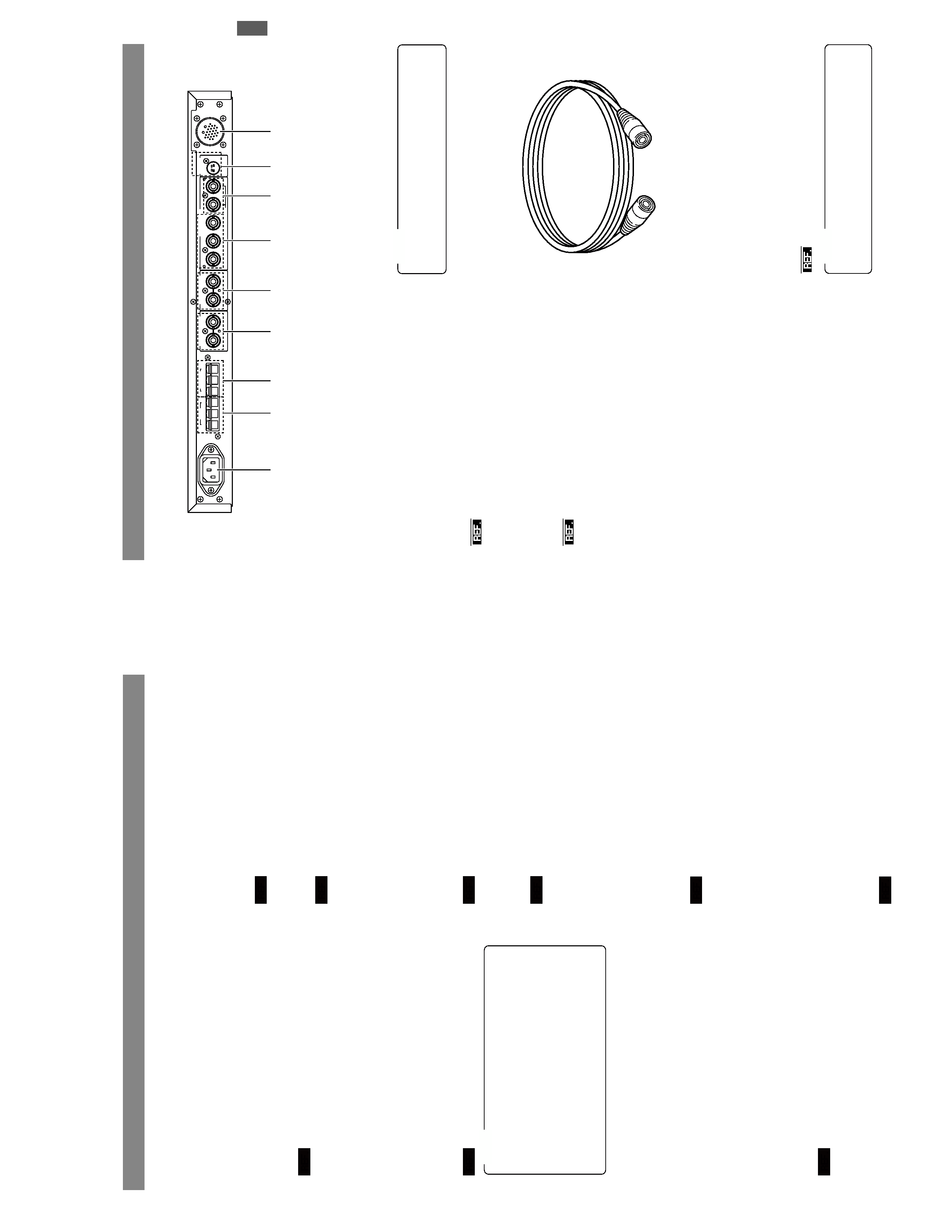
INTRODUCTION
CONTR
OLS,
CONNECT
ORS
AND
INDICA
T
ORS
(CONTINUED)
Rear
panel
HG
C
C
PVW
PGM
TALLY
INTERCOM
AUX
VIDEO
INPUT
GENLOCK
INPUT
VIDEO
OUTPUT
Y/C
OUT
CAMERA
CABLE
R/R-Y
B
/B-Y
COMPOSITE
VIDEO
G/Y
9
8
4
5
6
7
1
2
3
This
connector
outputs
Y/C
signals
only
when
Y/C
is
selected
as
the
output
from
the
R/R-Y
,G/Y
and
B/B-Y
connectors
6
.
NOTE
9
[CAMERA
CABLE]
connector
(26-pin)
Connect
this
socket
to
a
camera
using
the
optionally
avail-
able
camera
cables.
A
menu
setup
is
required
according
to
the
cables
in
use.
:
"
Setup
of
Camera
Cable
Length
"
on
page
12.
The
VC-P110
ser
ies
camer
a
cab
les
that
can
be
used
to
con-
nect
a
camera
to
the
RM-P210
are
available
in
four
lengths
as
listed
belo
w
.
VC-P110
:5
meters
VC-P112
:
20
meters
VC-P113
:
50
meters
VC-P114
:
100
meters
Camera
Cables
(Optional)
If
it
is
required
to
extent
the
cable,
use
the
KA-280
e
xtension
connector
.
The
total
cable
length
should
not
exceed
100
meters.
NOTE
E-6