SERVICE MANUAL
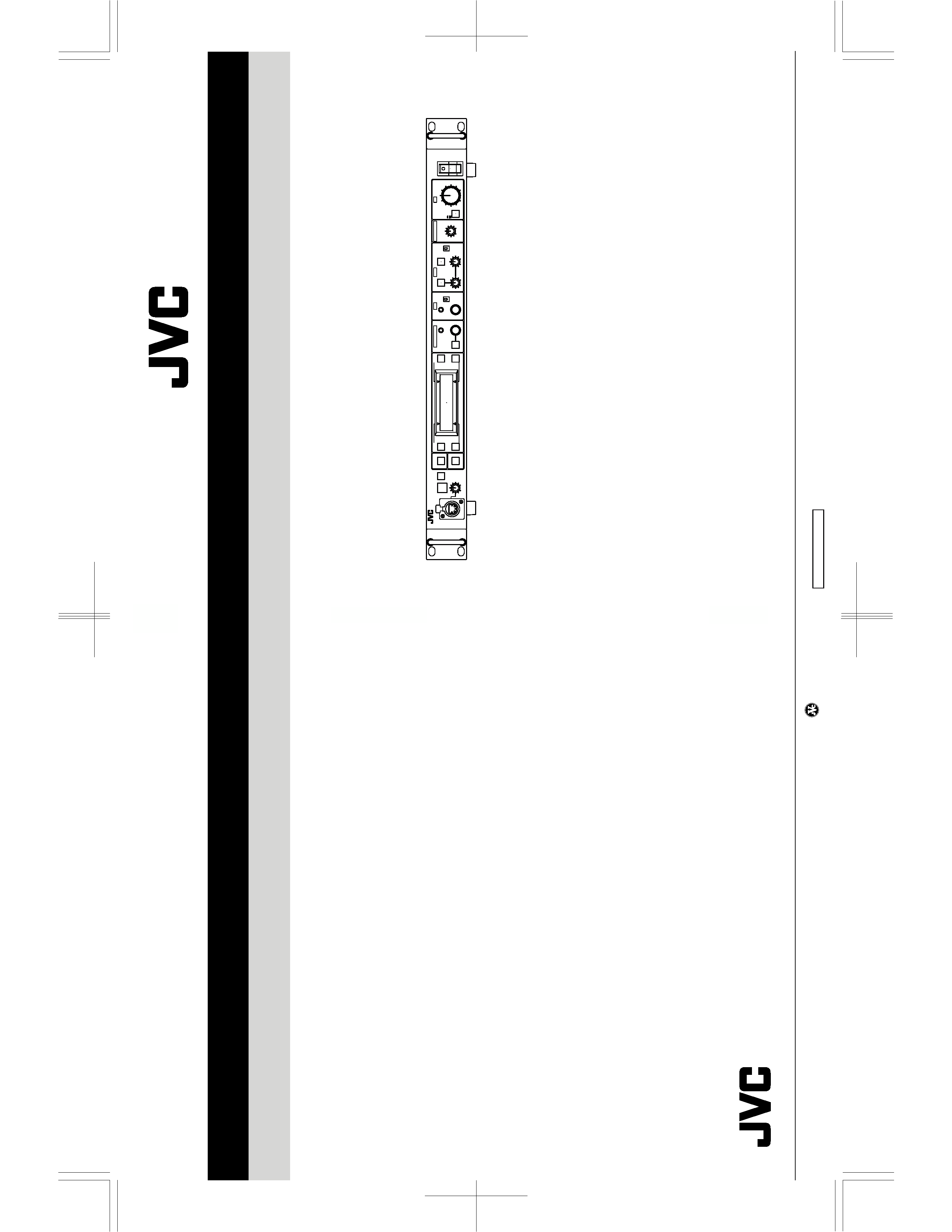
RM-P210U/RM-P210E
REMOTE CONTROL UNIT
No. 60136
April 2001
COPYRIGHT ' 2001 VICTOR COMPANY OF JAPAN, LTD.
Printed in Japan
(V.P.) A.I
VICTOR COMPANY OF JAPAN, LIMITED
100% recycled paper
RM-P210U/RM-P210E
No.
60136
CALL
TALLY
INTERCOM
LEVEL
FULL AUTO
F1
SHUTTER
GAIN
F2
F3
MENU/SHUTTER
GAIN
PAINT
AUTO
B
R
W.BAL
AUTO
MANU
WHITE
MASTER BLACK
POWER
I
O
IRIS
STEP
SHUTTER
MENU
PUSH-ON
DOWN
UP
VARIABLE
PUSH-ON
HIGH
LOW
B
A
PRESET
CLOSE
OPEN
MID
DOWN
UP
F4
BARS
REMOTE CONTROL UNIT RM-P210

TABLE OF CONTENTS
I IMPORTANT SAFETY PRECAUTIONS
I INSTRUCTIONS
1. SERVICE CAUTIONS AND DISASSEMBLY ............................................................................................................ 1-1
1.1 REMOVAL OF EXTERNAL COVER ..................................................................................................................... 1-1
1.2 FUNCTIONS AND SETTINGS OF INTERNAL SWITCHES .................................................................................. 1-2
1.3 ADJUSTMENT AND CHECK MODES ................................................................................................................ 1-3
2. ELECTRICAL ADJUSTMENT .................................................................................................................................... 2-1
2.1 INSTRUMENTS REQUIRED FOR ADJUSTMENTS, THEIR SETUPS ................................................................. 2-1
2.2 ADJUSTMENT MODE ........................................................................................................................................ 2-2
2.3 TRANSMIT VOLTAGE ADJUSTMENT ................................................................................................................ 2-3
2.4 COMPOSITE SIGNAL OUTPUT ADJUSTMENT ................................................................................................. 2-3
2.5 COMPONENT/RGB SIGNAL OUTPUT ADJUSTMENT ...................................................................................... 2-4
2.6 INTERCOM LEVEL ADJUSTMENT .................................................................................................................... 2-5
3. CHARTS AND DIGRAMS .......................................................................................................................................... 3-1
3.1 MAIN/FR1/FR2/CC/SUB1 BOARD SCHEMATIC DIAGRAM
01 / 02 / 03 / 04 / 05 ................................. 3-1
3.2 MAIN CIRCUIT BOARD
01 .............................................................................................................................. 3-2
3.3 FR1 CIRCUIT BOARD
02 ................................................................................................................................. 3-2
3.4 FR2 CIRCUIT BOARD
03 ................................................................................................................................. 3-2
3.5 CC CIRCUIT BOARD
04 ................................................................................................................................... 3-2
3.6 SUB1 CIRCUIT BOARD
05 ............................................................................................................................... 3-2
3.7 IC BLOCK DIAGRAM .......................................................................................................................................... 3-3
4. EXPLODED VIEW AND PARTS LIST ....................................................................................................................... 4-1
4.1 RM-P210 ASSEMBLY
M2 ................................................................................................................................. 4-1
5. ELECTRICAL PARTS LIST ......................................................................................................................................... 5-1
5.1 MAIN BOARD ASSEMBLY PARTS LIST
01..................................................................................................... 5-2
5.2 FR1 BOARD ASSEMBLY PARTS LIST
02........................................................................................................ 5-7
5.3 FR2 BOARD ASSEMBLY PARTS LIST
03........................................................................................................ 5-8
5.4 CC BOARD ASSEMBLY PARTS LIST
04 ......................................................................................................... 5-8
5.5 SUB1 BOARD ASSEMBLY PARTS LIST
05 ..................................................................................................... 5-8
6. PACKING ................................................................................................................................................................... 6-1
6.1 PACKING ASSEMBLY
M1................................................................................................................................ 6-1
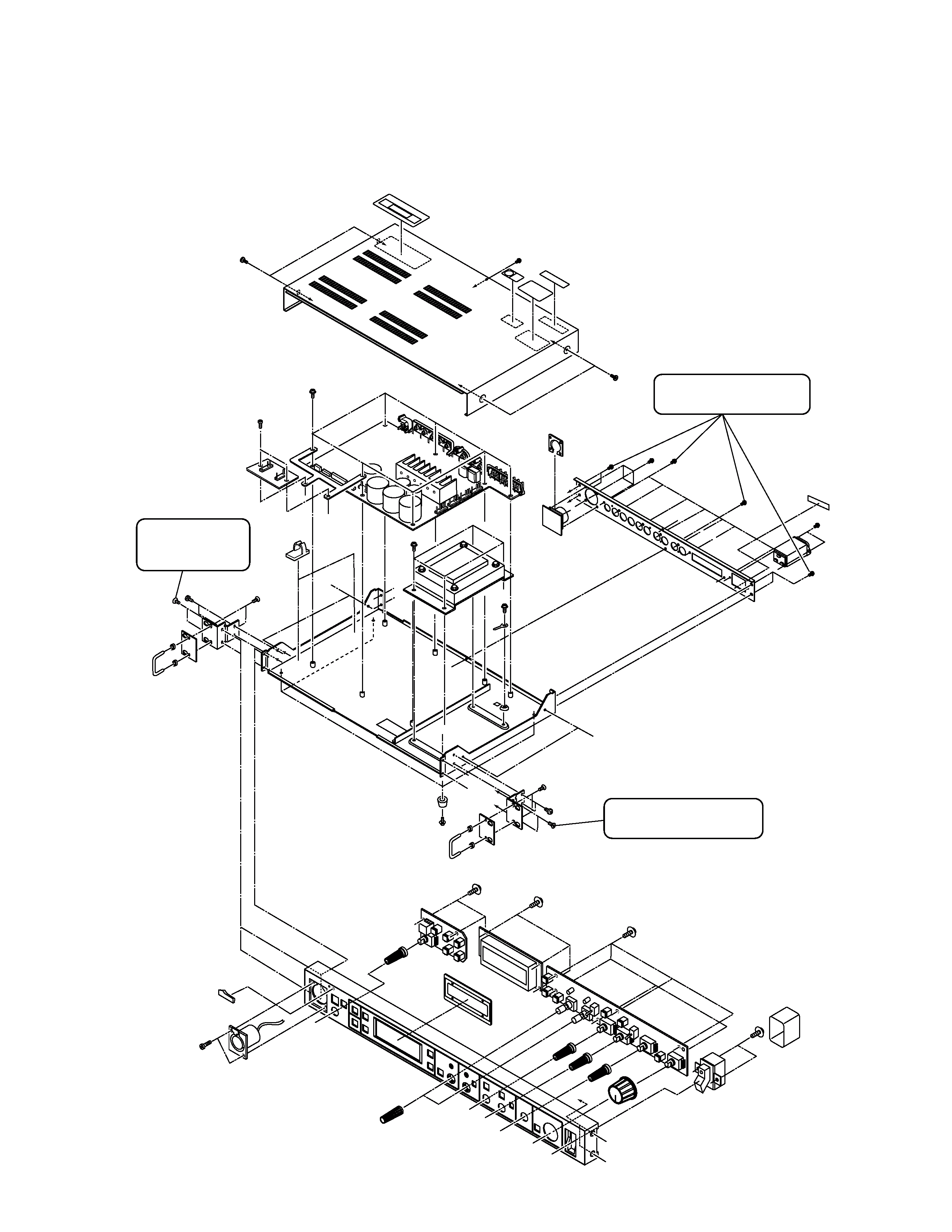
1-1
SECTION 1
SERVICE CAUTIONS AND DISASSEMBLY
1.1
REMOVAL OF EXTERNAL COVER
``D''
``F''
``E''
``E''
``C''
``C''
``D''
``A''
``E''
``A''
``B''
``B''
``A''
``A''
``B''
``C''
``F''
``C''
``D''
Remove these 2
screws to remove
the front panel.
Remove these 2 screws
to remove the front panel.
Remove these 12 screws
to remove the rear panel.
1-2
No.1
M
V
ON
OFF
S1
S603
CARBON
DYNAMIC
S601
S602
RTS
2W
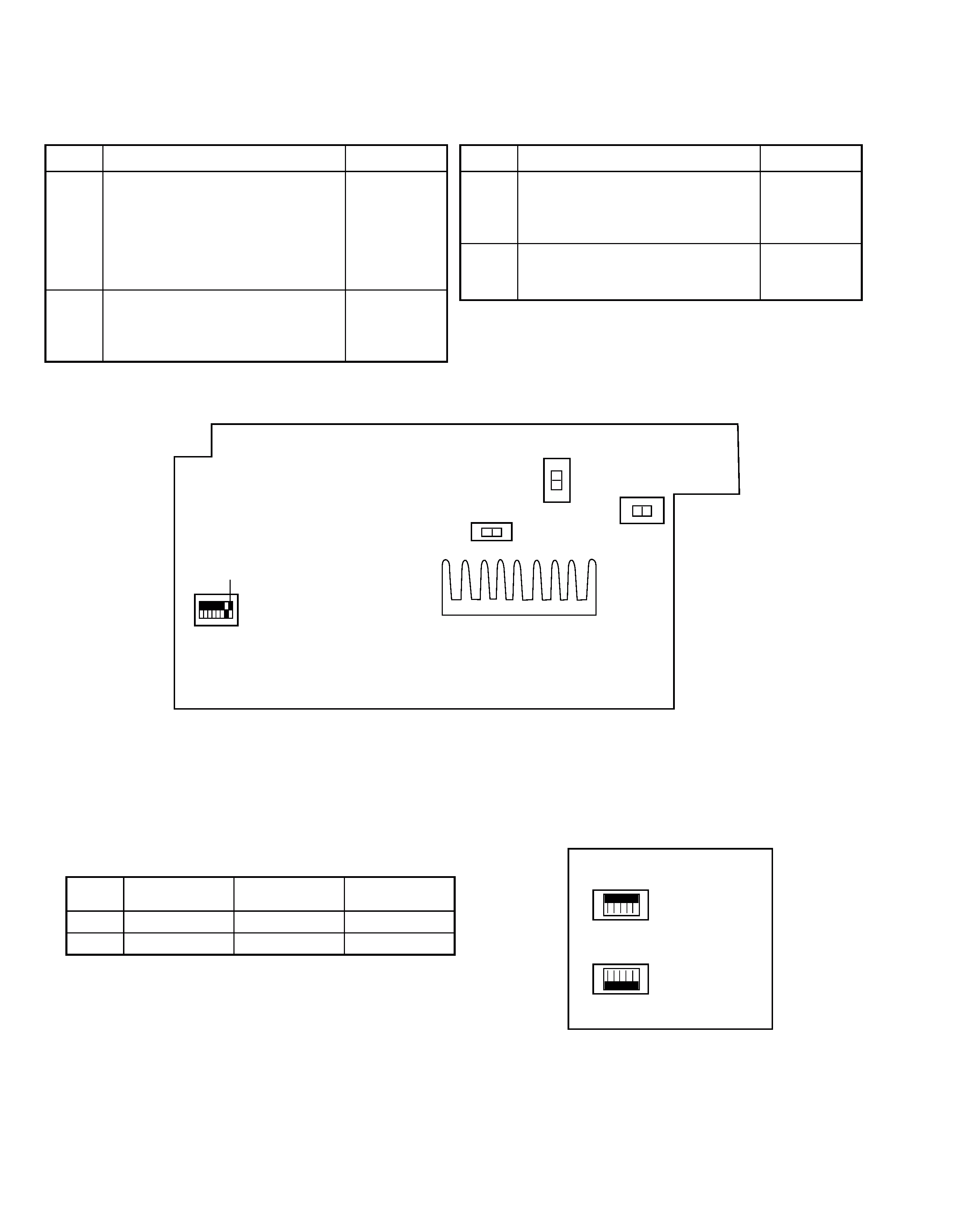
1.2
FUNCTIONS AND SETTINGS OF INTERNAL SWITCHES
1.2.1
MAIN Board
1.2.2
CC Board
Set switches S35 and S36 according to the connected camera cable.
MAIN Board (Rear Side)
CC Board
S1
U model:
No. 1 OFF
No. 2 OFF
E model:
No. 1 ON
No. 2 OFF
8-segment DIP switch to be set
according to the destination type.
No. 1 ON : PAL.
OFF: NTSC
No. 2 ON: Japan
OFF: USA
Nos. 3 to 8: Not used. (Set to OFF.)
S601
U model: M
E model: V
Tally input M/V switch
M: Make contact (ON when shorted)
V: Voltage (ON when AC or DC is applied)
Symbol
Function
Factory Setting
S602
U model: RTS
E model: 2W
Intercom headset 2W/RTS switch.
2W: 2-wire intercom
RTS: RTS intercom
S603
DYNAMIC
Intercom headset microphone
DYNAMIC/CARBON switch.
Symbol
Function
Factory Setting
S35
S36
All ON
All OFF
All OFF
All ON
All OFF
All ON
Symbol
Sony Cable
CCZ-A100 (100 m)
JVC Cable
Factory Setting
S35
S36
ON
OFF
ON
OFF
1-3
1.3
ADJUSTMENT AND CHECK MODES
1.3.1
Starting the Service Modes and Front Panel Check Mode
The RM-P210 incorporates the following service modes for use in servicing. Each of the service modes can be entered at the same
time as turning the RM-P210 ON and continues until it is turned OFF. Communications with the camera are not performed except in
the normal mode.
The following table shows the names of the modes and their details.
1.3.2
Data Clear Mode
Startup method
Hold the FULL AUTO , BARS and IRIS buttons simultaneously while press the POWER switch.
Operation Details
When the unit is started in the Data Clear mode, all EEPROM and SRAM data is initialized and the following message appears in
the LCD. After this, all operations are inhibited.
Normal
Data Clear
Hardware Check
Adjustment
Any other method than those described below.
Hold FULL AUTO , BARS and IRIS buttons
simultaneously while turning power ON.
Hold CALL , F1 and F2 buttons
simultaneously while turning power ON.
Hold MENU , F3 and F4 buttons
simultaneously while turning power ON.
This mode starts in normal operation by user.
All EEPROM and SRAM data are initialized.
Displays the program version.
Check of LEDs, SW, VR, JOG dials, etc.
For adjustments of supply voltage and cable length.
Mode Name
Startup Method
Contents
DATA CLEARED ! !
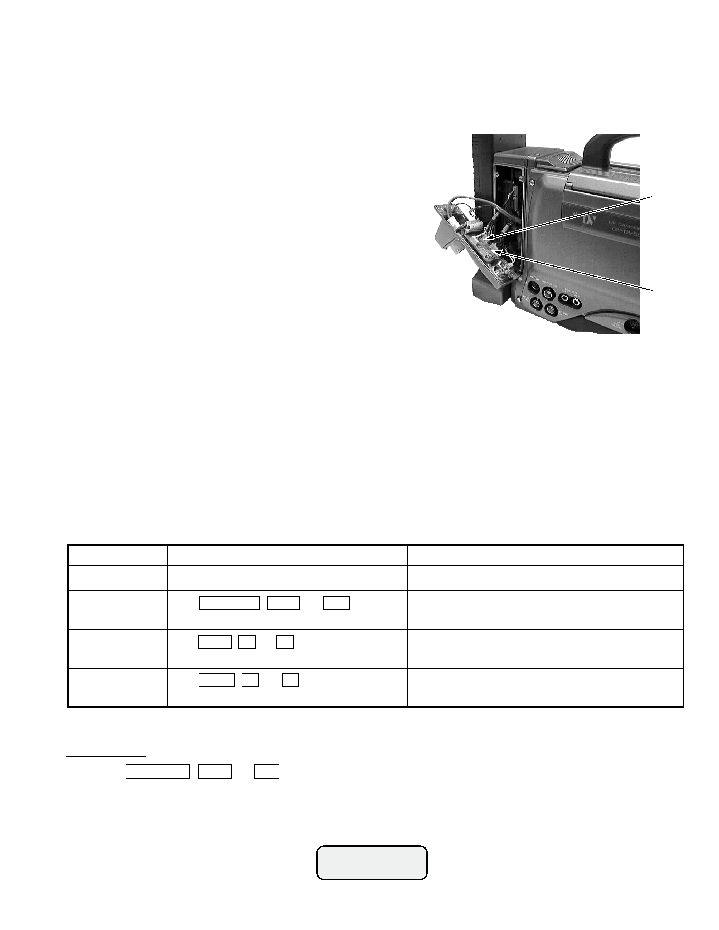
*HOW TO SET IT FOR USING SONY CABLE CCZ-A100.
Sony cable can be used by changing the setting as below only when RM-P210 is connected with GY-DV550. Sony has many type of
the cables but we can not check all the cable. Please do not use other than CCZ-A100.
1. GY-DV550 setting
Change the connection of the connector CN77 to CN83 on
56 CN board.
2. RM-P210 setting
(1) Change the setting of the switch on CC board
a) S35 : All switch have to be set to ON (UP side).
b) S36 : All switch have to be set to OFF (DOWN side).
(2) Re-adjustment of the transmit voltage (see "2.3 TRANSMIT VOLTAGE
ADJUSTMENT)
After re-adjustment, check the voltage between pin A and pin B in 26P
connector of RM-P210. It MUST be less than 15V. If it was more than
15V, adjustment of the b) and c) (+17V and +19V adjustment) have to
re-adjust to 15V from 16V.
a) +15V supply adjustment : adjust to 15
± 0.2VDC
b) +17V supply adjustment : adjust to 16
± 0.2VDC
c) +19V supply adjustment : adjust to 16
± 0.2VDC
Note 1: If the Voltage was not readjusted the View Finder will be damaged due to the heating problem.
Note 2: Difference between Sony cable and JVC cable is the impedance.
JVC cable: 1.3 Ohm
Sony cable: 0.8 Ohm.
CN77
CN83