SERVICE MANUAL
COPYRIGHT © 2005 Victor Company of Japan, Limited
No.MB369
2005/6
COMPACT COMPONENT SYSTEM
MB369
2005
6
MX-KC4
Lead free solder used in the board (material : Sn-Ag-Cu, melting point : 219 Centigrade)
TABLE OF CONTENTS
1
PRECAUTION. . . . . . . . . . . . . . . . . . . . . . . . . . . . . . . . . . . . . . . . . . . . . . . . . . . . . . . . . . . . . . . . . . . . . . . . . 1-3
2
SPECIFIC SERVICE INSTRUCTIONS . . . . . . . . . . . . . . . . . . . . . . . . . . . . . . . . . . . . . . . . . . . . . . . . . . . . . . 1-4
3
DISASSEMBLY . . . . . . . . . . . . . . . . . . . . . . . . . . . . . . . . . . . . . . . . . . . . . . . . . . . . . . . . . . . . . . . . . . . . . . . 1-5
4
ADJUSTMENT . . . . . . . . . . . . . . . . . . . . . . . . . . . . . . . . . . . . . . . . . . . . . . . . . . . . . . . . . . . . . . . . . . . . . . . 1-17
5
TROUBLESHOOTING . . . . . . . . . . . . . . . . . . . . . . . . . . . . . . . . . . . . . . . . . . . . . . . . . . . . . . . . . . . . . . . . . 1-17
CA-MXKC4
SP-MXKC4
SP-MXKC4
Area suffix
A ------------------------ Australia
UW ----------- Brazil,Mexico,Peru
UY ------------------------ Argentina
UJ ---------------------- U.S.Military
1-2 (No.MB369)
SPECIFICATION
Amplifier
Speaker Specifications (each unit)
Power Specifications
Design and specifications are subject to change without notice.
Output Power
140 W per channel, min. RMS, driven into 6
at 1kHz, with no
more than 10% total harmonic distortion (IEC 268-3)
Input Sensitivity/
Impedance (1 kHz)
AUX IN
400 mV/50 k
Speaker terminals
6
- 16
Phones
32
- 1 k
15 mW/ch output into 32
Cassette Deck Section Frequency Response Type l (NORMAL) 63 Hz - 12 500 Hz
Wow And Flutter
0.15% (WRMS)
CD Player
CD Capacity
3 CDs
Dynamic Range
85 dB
Signal-To-Noise Ratio
85 dB
Wow And Flutter
Unmeasurable
Tuner
FM Tuner
87.50 MHz - 108.00 MHz for A
AM Tuner
522 kHz - 1710 kHz for A
530 kHz - 1710 kHz (at AM10 kHz channel space) for UW, UJ, UY
531 kHz - 1710 kHz (at AM9 kHz channel space) for UW, UJ, UY
Unit
Dimensions
270 mm
× 306 mm × 456 mm (W/H/D)
Mass
Approx. 8.6 kg
Type
3-way bass-reflex type
Speaker Unit
Woofer
16 cm cone
× 1
Mid
5cm cone
× 1
Tweeter
2cm dome
× 1
Power Handling Capacity
140 W
Impedance
6
Frequency Range
45 Hz - 22 000 Hz
Sound pressure level
87 dB/W·m
Dimensions
266 mm
× 333 mm × 241 mm (W/H/D)
Mass
Approx. 3.9 kg
Power Requirements
AC 240V 50Hz for A
AC 110 V/127 V/220 V/230 V-240 V , adjustable with voltage selector, 50 Hz/60 Hz for UW, UJ, UY
Power Consumption
140 W (power on mode)
22 W (in Standby mode)
(No.MB369)1-3
SECTION 1
PRECAUTION
1.1
Safety Precautions
(1) This design of this product contains special hardware and
many circuits and components specially for safety purpos-
es. For continued protection, no changes should be made
to the original design unless authorized in writing by the
manufacturer. Replacement parts must be identical to
those used in the original circuits. Services should be per-
formed by qualified personnel only.
(2) Alterations of the design or circuitry of the product should
not be made. Any design alterations of the product should
not be made. Any design alterations or additions will void
the manufacturers warranty and will further relieve the
manufacture of responsibility for personal injury or property
damage resulting therefrom.
(3) Many electrical and mechanical parts in the products have
special safety-related characteristics. These characteris-
tics are often not evident from visual inspection nor can the
protection afforded by them necessarily be obtained by us-
ing replacement components rated for higher voltage, watt-
age, etc. Replacement parts which have these special
safety characteristics are identified in the Parts List of Ser-
vice Manual. Electrical components having such features
are identified by shading on the schematics and by (
) on
the Parts List in the Service Manual. The use of a substitute
replacement which does not have the same safety charac-
teristics as the recommended replacement parts shown in
the Parts List of Service Manual may create shock, fire, or
other hazards.
(4) The leads in the products are routed and dressed with ties,
clamps, tubings, barriers and the like to be separated from
live parts, high temperature parts, moving parts and/or
sharp edges for the prevention of electric shock and fire
hazard. When service is required, the original lead routing
and dress should be observed, and it should be confirmed
that they have been returned to normal, after reassem-
bling.
(5) Leakage shock hazard testing
After reassembling the product, always perform an isola-
tion check on the exposed metal parts of the product (an-
tenna terminals, knobs, metal cabinet, screw heads,
headphone jack, control shafts, etc.) to be sure the product
is safe to operate without danger of electrical shock.Do not
use a line isolation transformer during this check.
· Plug the AC line cord directly into the AC outlet. Using a
"Leakage Current Tester", measure the leakage current
from each exposed metal parts of the cabinet, particular-
ly any exposed metal part having a return path to the
chassis, to a known good earth ground. Any leakage cur-
rent must not exceed 0.5mA AC (r.m.s.).
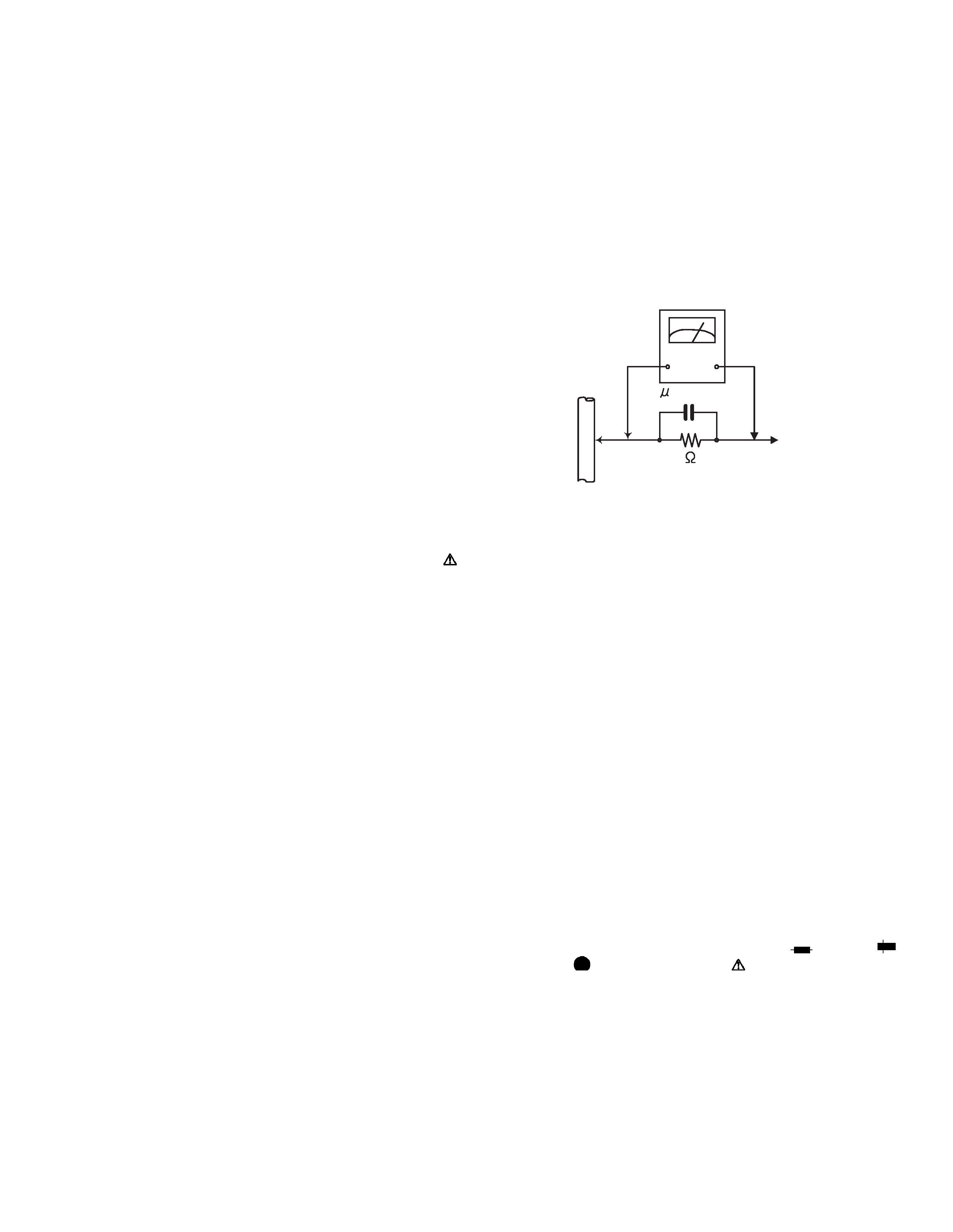
· Alternate check method
Plug the AC line cord directly into the AC outlet. Use an
AC voltmeter having, 1,000
per volt or more sensitivity
in the following manner. Connect a 1,500
10W resistor
paralleled by a 0.15
µF AC-type capacitor between an ex-
posed metal part and a known good earth ground.
Measure the AC voltage across the resistor with the AC
voltmeter.
Move the resistor connection to each exposed metal
part, particularly any exposed metal part having a return
path to the chassis, and measure the AC voltage across
the resistor. Now, reverse the plug in the AC outlet and
repeat each measurement. Voltage measured any must
not exceed 0.75 V AC (r.m.s.). This corresponds to 0.5
mA AC (r.m.s.).
1.2
Warning
(1) This equipment has been designed and manufactured to
meet international safety standards.
(2) It is the legal responsibility of the repairer to ensure that
these safety standards are maintained.
(3) Repairs must be made in accordance with the relevant
safety standards.
(4) It is essential that safety critical components are replaced
by approved parts.
(5) If mains voltage selector is provided, check setting for local
voltage.
1.3
Caution
Burrs formed during molding may be left over on some parts
of the chassis.
Therefore, pay attention to such burrs in the case of pre-
forming repair of this system.
1.4
Critical parts for safety
In regard with component parts appearing on the silk-screen
printed side (parts side) of the PWB diagrams, the parts that are
printed over with black such as the resistor (
), diode (
)
and ICP (
) or identified by the "
" mark nearby are critical
for safety. When replacing them, be sure to use the parts of the
same type and rating as specified by the manufacturer.
(This regulation dose not Except the J and C version)
Good earth ground
Place this
probe on
each exposed
metal part.
AC VOLTMETER
(Having 1000
ohms/volts,
or more sensitivity)
1500
10W
0.15 F AC TYPE

1-4 (No.MB369)
SECTION 2
SPECIFIC SERVICE INSTRUCTIONS
This service manual does not describe SPECIFIC SERVICE INSTRUCTIONS.
(No.MB369)1-5
SECTION 3
DISASSEMBLY
3.1
Disassembly of the main blocks of the set
Replacement of the fuses and the power IC.
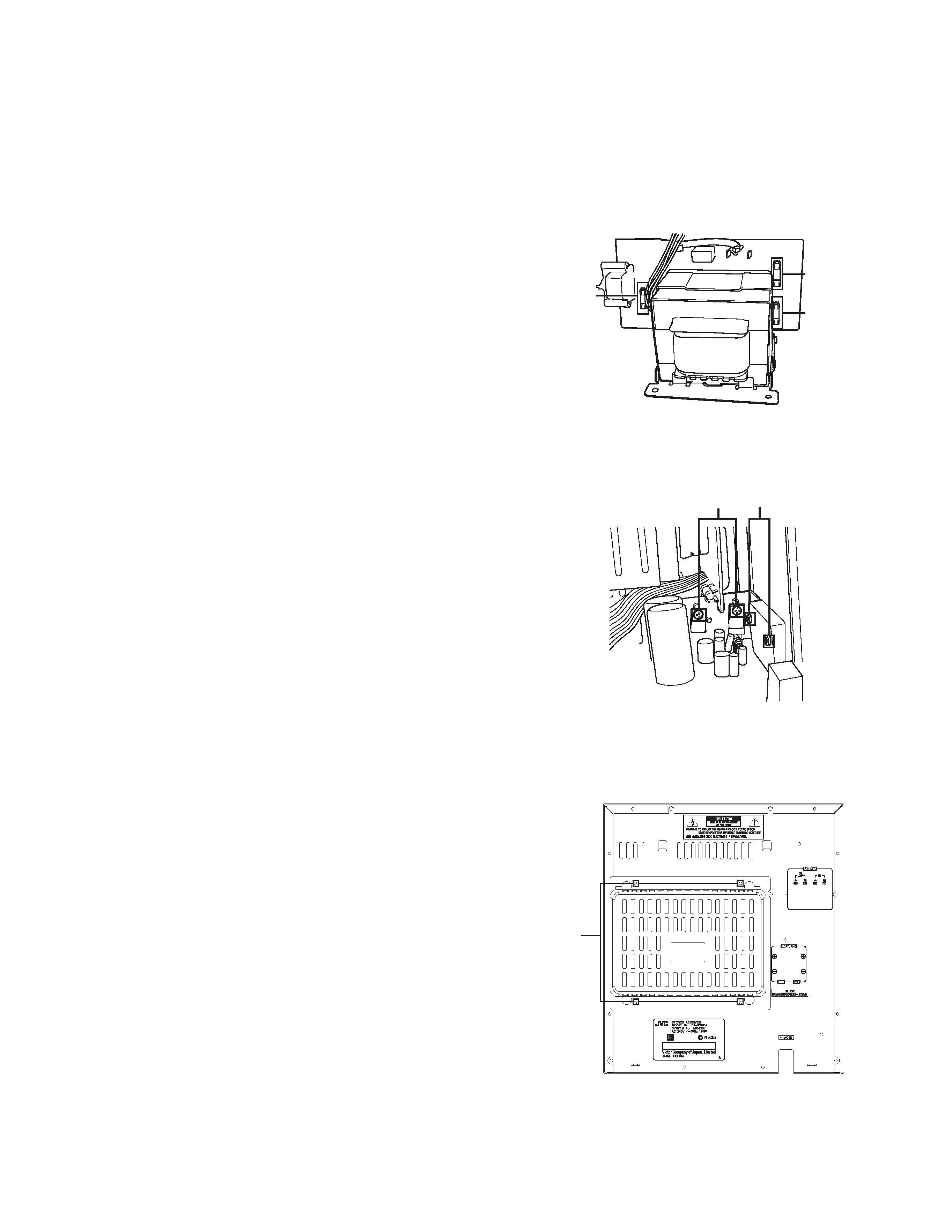
3.1.1 Replacing the fuses
(See Fig.1)
· Prior to performing the following procedure, remove the left
side BOARD.
(1) Replace the fuses inside.
Caution:
Be sure to use fuses with the specified ratings.
Fig.1
3.1.2 Replacing the power IC
(See Fig.2)
· Prior to performing the following procedure, remove the top
cover.
(1) Remove the two screws A from the heat sink between the
power IC.
(2) Remove the solder fixing the power IC.
Fig.2
3.1.3 Replacing the heat sink cover
(See Fig.3)
(1) Remove four screws B from the rear panel.
(2) Pull the heat sink cover outward.
Fig.3
Fuse (F951)
T3.15AL 250V
Fuse (F952)
T1.6AL 250V
Fuse (F953)
T1.6AL 250V
W
A
For CA-MXKC4 A
B