SERVICE MANUAL
MOBILE TV TUNER SYSTEM
No.49654
Aug. 2001
COPYRIGHT
2001 VICTOR COMPANY OF JAPAN, LTD.
KV-C10
KV-C10
HEADPHONE
ANTENNA INPUT
INPUT 2
INPUT 1
12
23
4
VIDEO
L
R
VIDEO
CONT
AUDIO
L
R
AUDIO
VIDEO
1
OUTPUT
RL
VIDEO
TO DISPLAY
VOCAL
POWER
SUPPLY
AUDIO
Contents
Safety precautions
Disassembly method
Adjustment method
Description of major ICs
1 2
1 3
1 4
1 6~13
Area Suffix
J ----- Northern America
KV-C10
1-2
!
Burrs formed during molding may be left over on some parts of the chassis. Therefore,
pay attention to such burrs in the case of preforming repair of this system.
Safety precaution
KV-C10
1-3
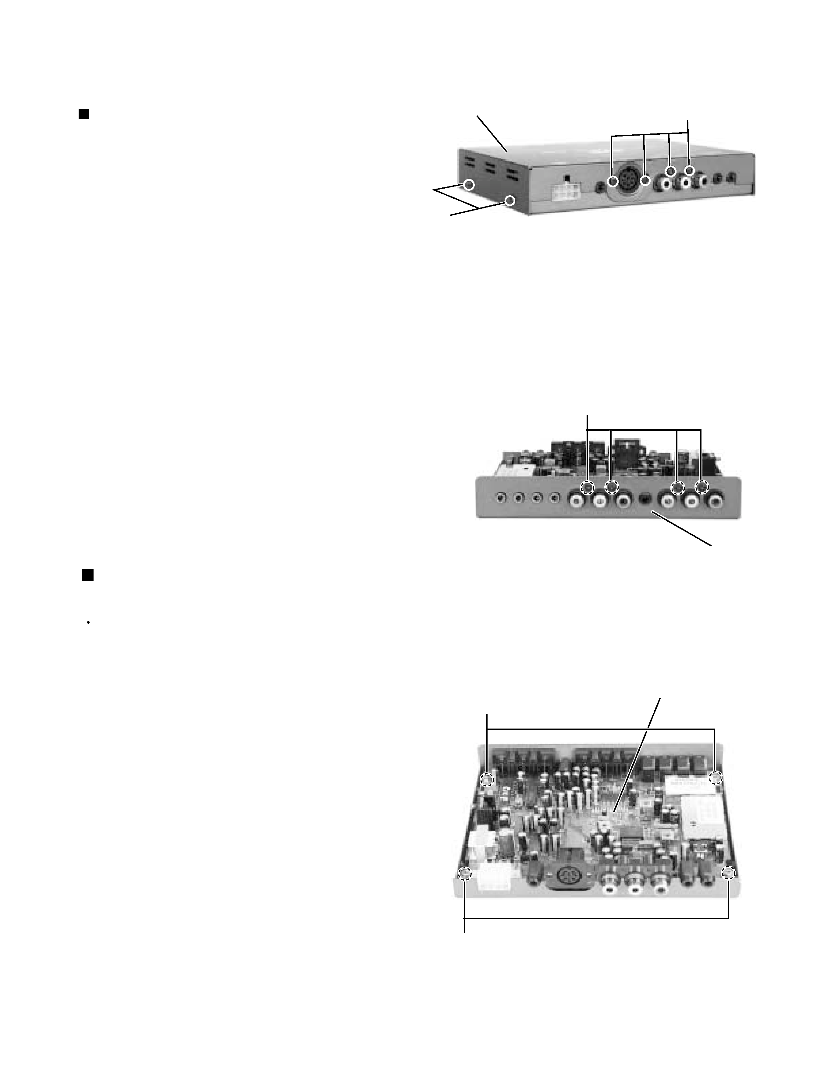
Remove the four screws A attaching the metal cover
on the back of the body.
Remove the four screws B attaching the metal cover
on both sides of the body.
Remove the metal cover from the body by lifting the
rear part of the cover.
1.
2.
3.
Disassembly method
Removing the metal cover
(See Fig.1)
Prior to performing the following procedure, remove
the metal cover.
Remove the four screws C attaching the pin jack
and the main board.
Remove the four screws D attaching the main
board.
1.
2.
Removing the main board
(See Fig.2 to 3)
Fig.1
Fig.2
Fig.3
Metal cover
A
D
D
Front panel
Main board
B
C
KV-C10
1-4
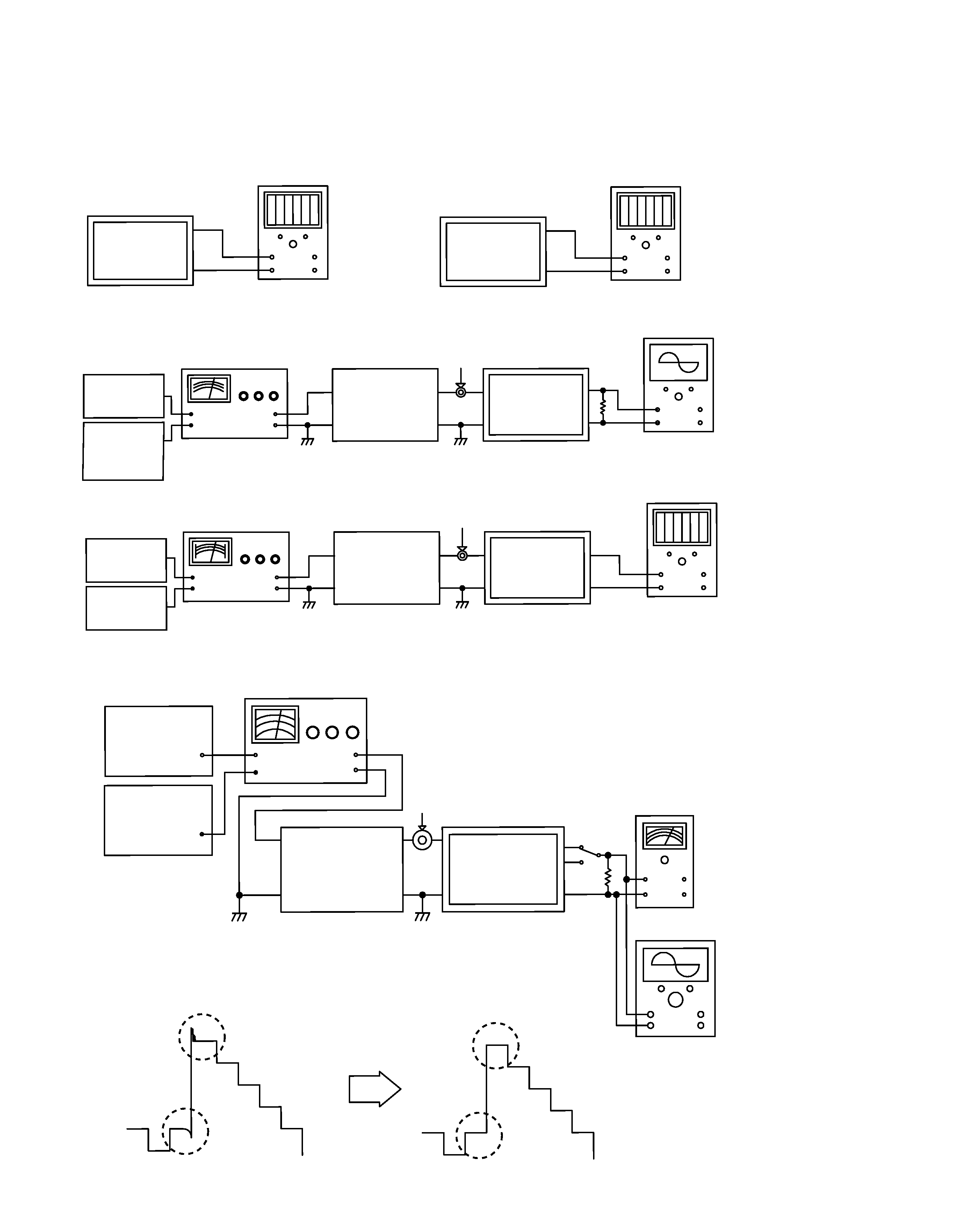
Adjustment method
1. Connection
DC volt meter
Fig. 1
Fig. 2
Digital counter
TP201
TP202
GND
GND
+
-
+
-
+
-
+
-
Fig. 3
Fig. 4
TP202
GND
GND
Video output
75 ohm
Unit under test
Unit under test
Antenna receptacle
Antenna receptacle
TV Signal generator
TV Signal generator
Video
pattern
generator
Video
pattern
generator
FM
Signal
generator
FM
Signal
generator
Oscilloscope
DC Volt meter
+
-
+
-
Attenuator
Attenuator
Fig. 5
Fig. 6
TV Signal generator
Antenna receptacle
AC VTVM
Oscilloscope
47 kohm
Unit under test
Audio output
Attenuator
Video
pattern
generator
FM
Signal
generator
GND
+
-
+
-
+
-
L
R
KV-C10
1-5
3. Control settings
4. Adjust procedures
Fig. 7
2. Main board test point location
Step
1
2
3
4
5
Description
Antenna
level
adjustment
H.Sync
adjustment
PIF coil
adjustment
RF AGC
Adjustment
Audio
adjustment
Connection
Fig. 1
Fig. 2
Fig. 3
Fig. 4
Fig. 5
Signal generator
Color bar
Ch 12
60 dBuV
Color bar
Ch 12
60 dBuV
Ch 12
60 dBuV
TV Channel
Ch 12
Ch 12
Ch 12
Test point
TP201
TP202
Video
output
TP101
Audio
output
Adjustment
Adjust VR202
for 1.3V
Adjust VR201
for 15.73kHz
Adjust L101
for see Fig. 6
Adjust VR101
for 3.5V
Adjust L103
for max.output
Power switch ---------------------------------- On
TV channel ------------------------------------ Center position
Video pattern generator -------------------- Color bar
TP201
ANT.LEVEL
VR202
TP202
H.SYNC
L103
L101
TP101
AGC
VR101
IC201
VR201
(Reverse side)
(Foward side)