SERVICE MANUAL
CASSETTE RECEIVER
No.49627
FEB. 2001
COPYRIGHT
2001 VICTOR COMPANY OF JAPAN, LTD.
KS-FX901/KS-FX801
KS-FX901/KS-FX801
Area Suffix
U
Other areas
Scan
Music
Multi
MO
DISP
DISP
SCAN
SCAN
LOUD
LOUD
8
9
10
11
12
7
RM-RK31
Scan
Music
Multi
MO
DISP
DISP
SCAN
SCAN
LOUD
LOUD
8
9
10
11
12
7
RM-RK31
KS-FX901
KS-FX801
Contents
Safety precaution
Disassembly method
Adjustment method
Description of major ICs
1- 2
1- 3
1-11
1-15~25
Difference
point
KS-FX901
KS-FX801
Front
panel
Light Gold
Metallic Gray
Trim
plate
Light Gold
Gray
LCD
color
Multi color
White

KS-FX901/KS-FX801
1-2
!
Burrs formed during molding may be left over on some parts of the chassis. Therefore,
pay attention to such burrs in the case of preforming repair of this system.
Safety precaution
KS-FX901/KS-FX801
1-3
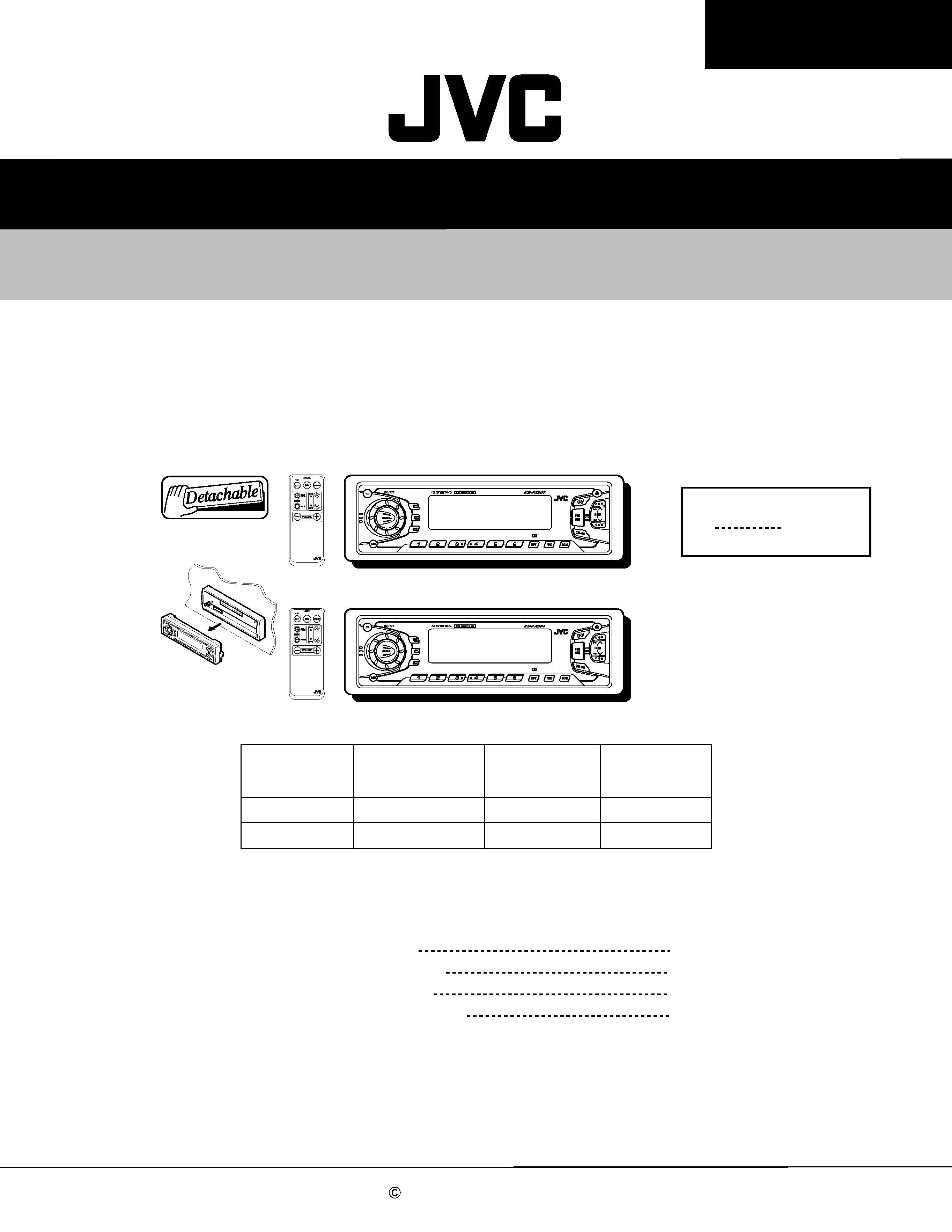
Disassembly method
1.
2.
Remove the two screws A attaching the front
chassis.
Insert a screwdriver to the two joints a on the side
of the front chassis, two joints b on the right side
and one joint c from upside, then detach the front
chassis toward the front side.
Removing the front chassis (See Fig.1~2)
Removing the heat sink (See Fig.3)
1. Remove the three screws B attaching the heat sink
on the left side of the body, and remove the heat
sink.
b
a
a
b
c
A
B
B
B
Heat sink
Fig.2
Fig.1
Fig. 3
Front chassis
KS-FX901/KS-FX801
1-4
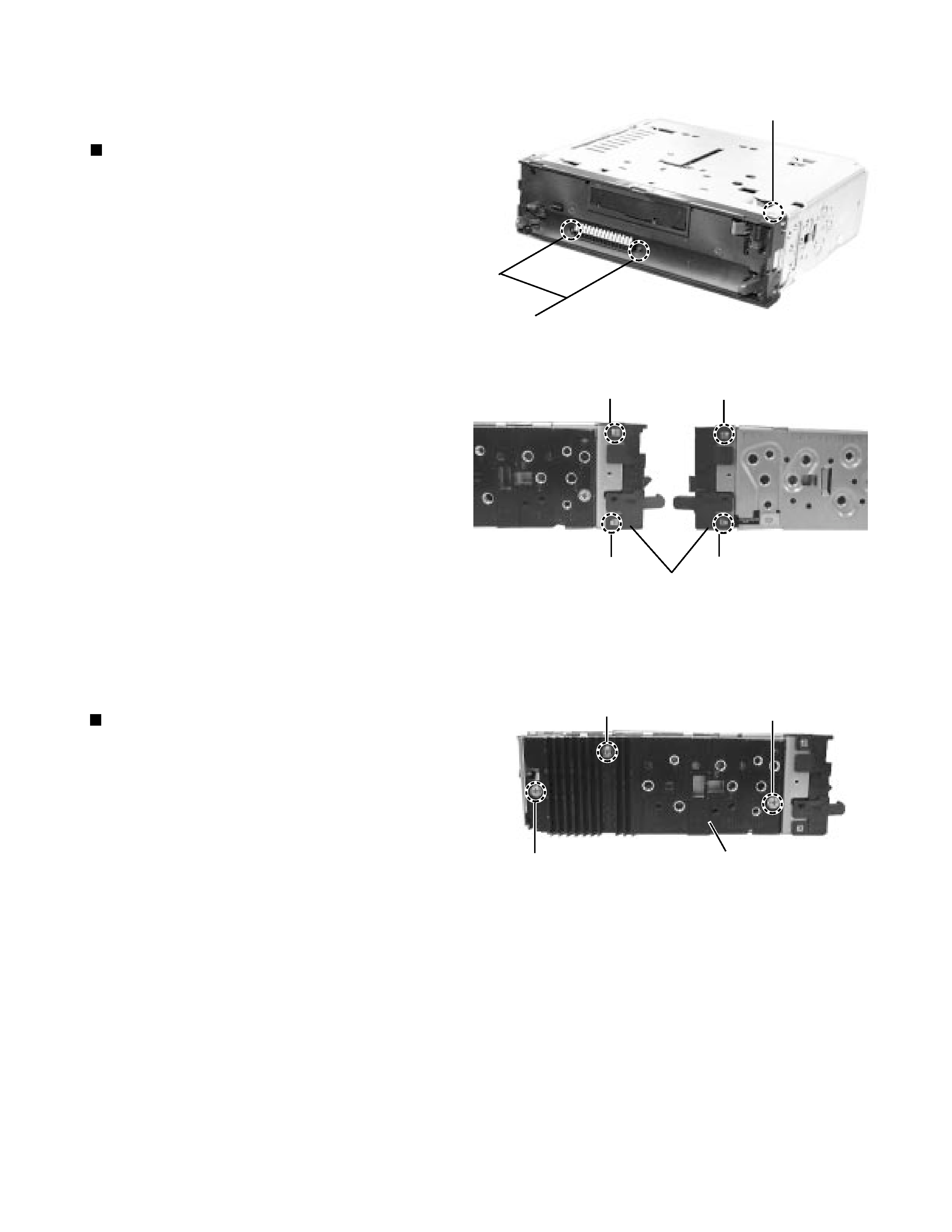
Removing the bottom cover (See Fig.4)
1.
2.
Turn the body upside down.
Insert a screwdriver to the two joints d and two
joints e on both sides of the body and the joint f on
the back of the body, then detach the bottom cover
from the body.
Removing the rear panel (See Fig.5 )
1.
2.
3.
4.
Remoe the front chassis.
Remove the heat sink.
Remove the bottom cover.
Remove the seven screws B attaching the rear
panel and one screw C attaching the pine jack on
the back of the body.
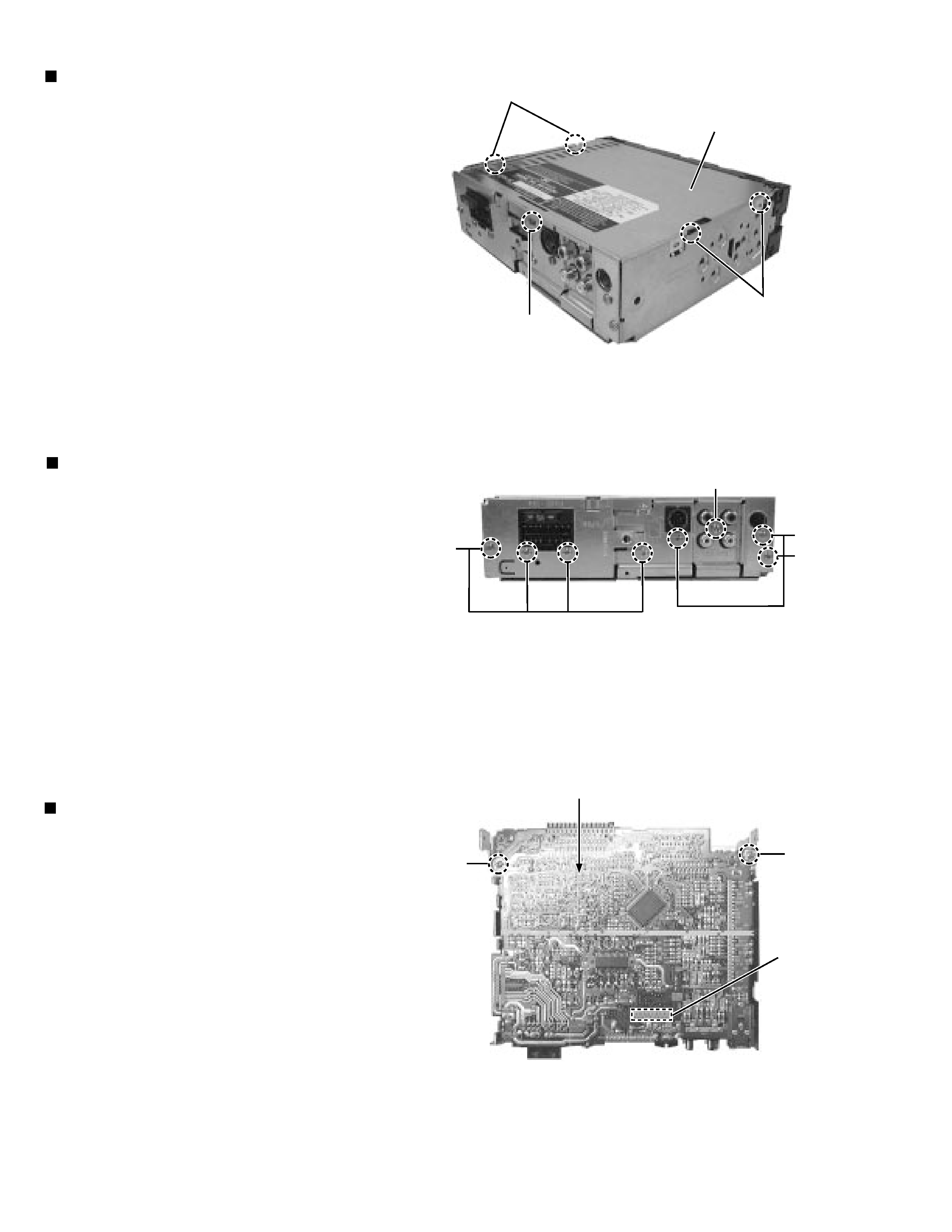
Removing the main amplifier board
assembly
(See Fig.6)
1.
2.
3.
4.
5.
Remove the front chassis.
Remove the bottom cover.
Remove the rear panel.
Remove the two screws D attaching the main
amplifier board assembly on the top cover.
Disconnect connector CP701 on the main amplifier
board assembly from the cassette mechanism
assembly.
d
e
f
Bottom cover
Fig. 4
Fig. 5
Fig. 6
B
C
B
B
D
D
CP701
Main board assembly
KS-FX901/KS-FX801
1-5
Cassette mechanism assembly
F
F
F
Top cover
Fig. 7
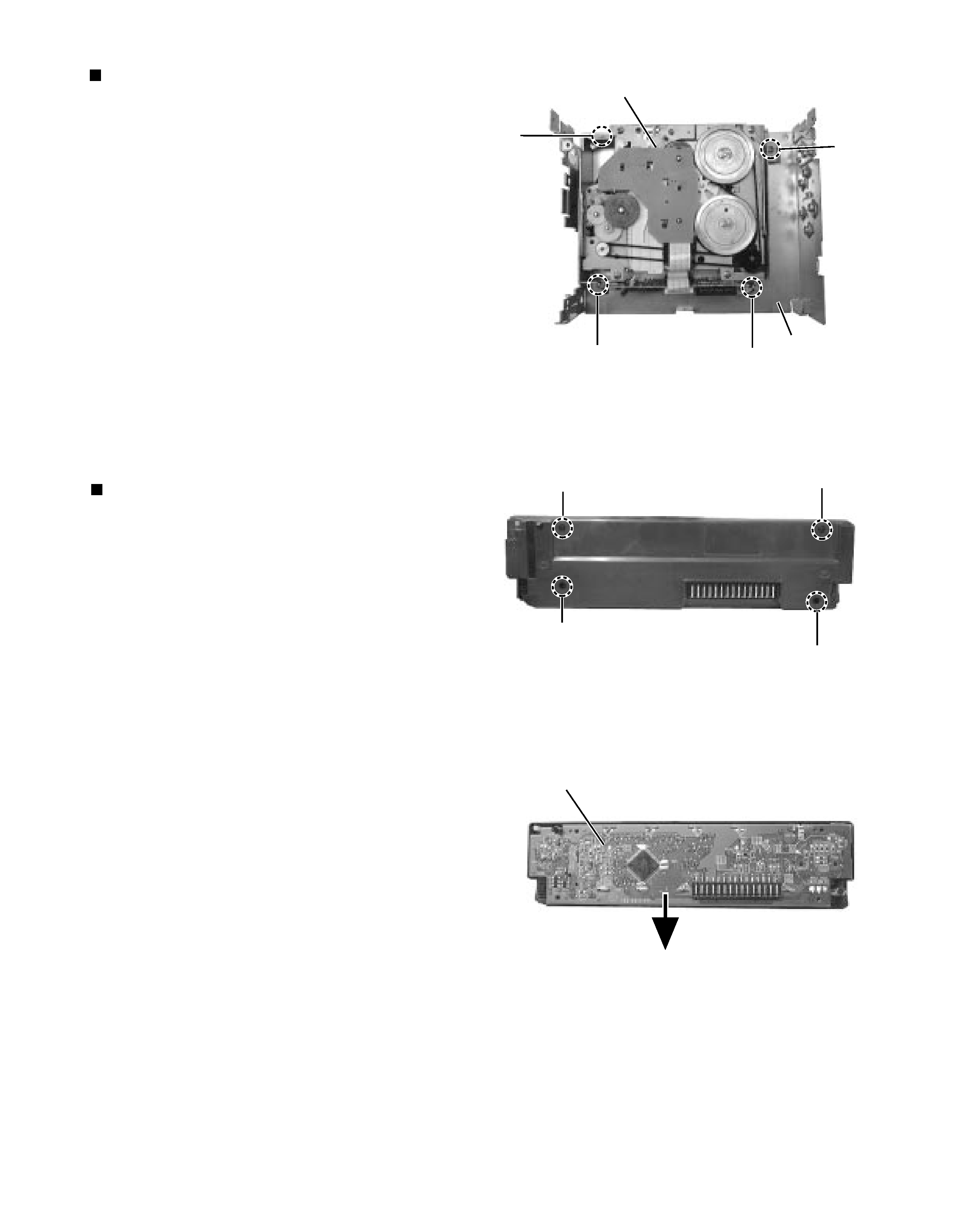
G
G
G
G
Fig. 8
Fig. 9
LCD & Key control board
F
Removing the Cassette mechanism
assembly
(See Fig.7)
1.
2.
3.
4.
Remove the front chassis.
Remove the bottom cover.
Remove the main amplifier board assembly.
Remove the fore screws F attaching the cassette
mechanism assembly from the top cover.
Removing the control switch board
(See Fig.8 and 9 )
1.
2.
3.
Remove the front panel unit from the main body.
Remove the four screws G attaching the rear cover
on the back of the front panel unit.
Remove the control switch board from the front
panel unit.