SERVICE MANUAL
COPYRIGHT © 2003 VICTOR COMPANY OF JAPAN, LTD.
No.49816
2003/03
KS-FX742R
CASSETTE RECEIVER
49816
2003
03
KS-FX742R
TABLE OF CONTENTS
1
Safety precaution . . . . . . . . . . . . . . . . . . . . . . . . . . . . . . . . . . . . . . . . . . . . . . . . . . . . . . . . . . . . . . . . . . . . . 1-2
2
Disassembly method . . . . . . . . . . . . . . . . . . . . . . . . . . . . . . . . . . . . . . . . . . . . . . . . . . . . . . . . . . . . . . . . . . 1-3
3
Adjustment. . . . . . . . . . . . . . . . . . . . . . . . . . . . . . . . . . . . . . . . . . . . . . . . . . . . . . . . . . . . . . . . . . . . . . . . . . 1-17
4
Description of major ICs . . . . . . . . . . . . . . . . . . . . . . . . . . . . . . . . . . . . . . . . . . . . . . . . . . . . . . . . . . . . . . . 1-21
Area Suffix
E ---------- Continental Europe
EX -------------- Central Europe

KS-FX742R
1-2 (No.49816)
SECTION 1
Safety precaution
CAUTION
Burrs formed during molding may be left over on some parts of the chassis. Therefore, pay attention to such burrs in
the case of preforming repair of this system.
KS-FX742R
(No.49816)1-3
SECTION 2
Disassembly method
2.1 Main body
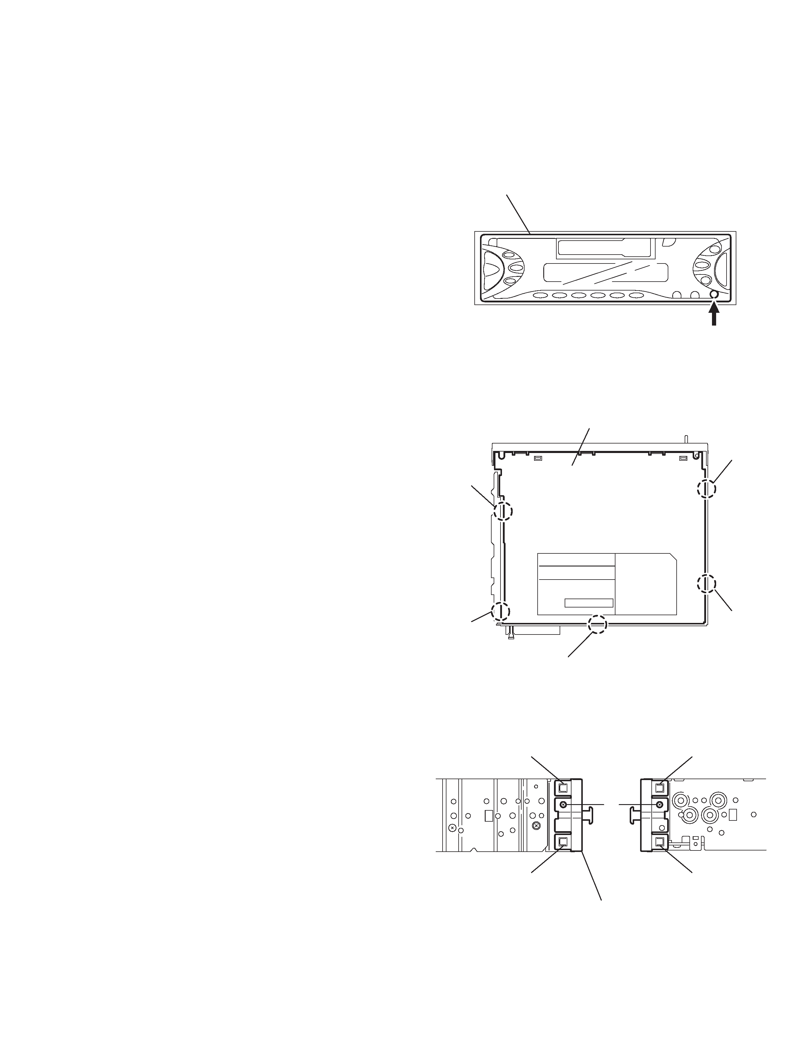
2.1.1 Removing the front panel assembly
(See Fig.1)
(1) Press the release button and remove the front panel as-
sembly.
Fig.1
2.1.2 Removing the bottom cover
(See Fig.2)
· Prior to performing the following procedure, remove the front
panel assembly.
(1) Turn the body upside down.
(2) Insert a screwdriver under the joints to release the two
joints a on the left side, the two joints b on the right side and
the joint c on the back of the body, then remove the bottom
cover from the body.
CAUTION:
When releasing the joint c using a screwdriver, do not damage
the main board.
Fig.2
2.1.3 Removing the front chassis
(See Fig.3)
· Prior to performing the following procedure, remove the front
panel assembly and bottom cover.
(1) Remove the screw A on each side of the body.
(2) Release the two joints d and the two joints e on the sides,
then remove the front chassis toward the front.
Fig.3
Front panel assembly
Release button
Bottom cover
Joint b
Joint b
Joint c
Joint a
Joint a
Joint d
Joint e
Front chassis
Joint d
A
Joint e
KS-FX742R
1-4 (No.49816)
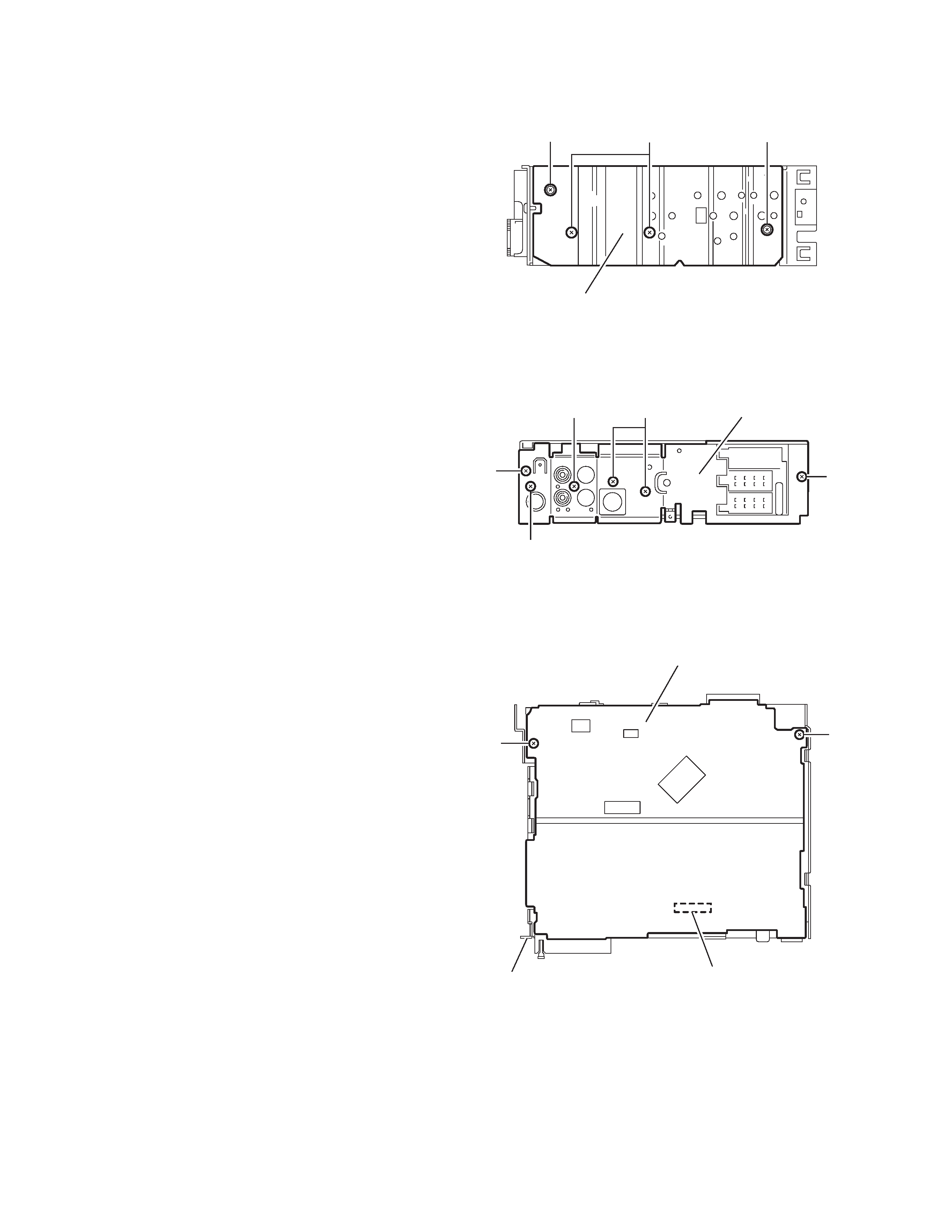
2.1.4
Removing the heat sink
(See Fig.4)
· Prior to performing the following procedure, remove the front
panel assembly.
(1) Remove the two screws B and two screws C attaching the
heat sink on the left side of the body, and remove the heat
sink.
Fig.4
2.1.5
Removing the rear panel
(See Fig.5 )
· Prior to performing the following procedure, remove the front
panel assembly and bottom cover.
(1) Remove the two screws D, three screws E and one screws
F attaching the rear panel on the back of the body.
Fig.5
2.1.6
Removing the main board
(See Fig.6)
· Prior to performing the following procedure, remove the front
panel assembly, bottom cover, front chassis, heat sink and
rear panel.
(1) Remove the two screws G attaching the main board on the
top chassis.
(2) Disconnect the connectors CN401 on the main board from
the cassette mechanism assembly.
Fig.6
Heat sink
CB
C
D
D
E
F
E
Rear panel
G
G
Main board assembly
CP401
Top chassis
KS-FX742R
(No.49816)1-5
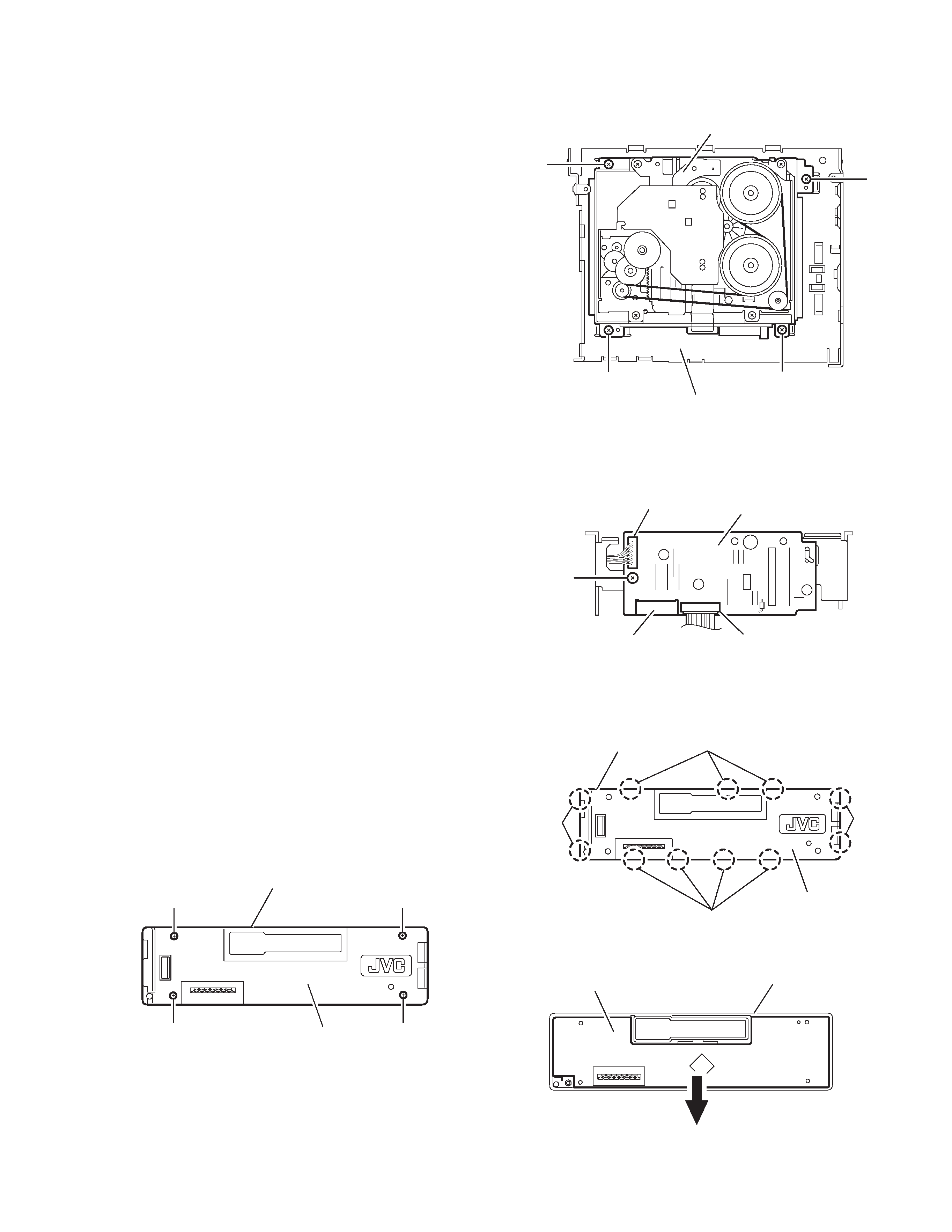
2.1.7 Removing the cassette mechanism assembly
(See Fig.7)
· Prior to performing the following procedure, remove the front
panel assembly, bottom cover, front chassis, heat sink, rear
panel and main board.
(1) Remove the four screws H attaching the cassette mecha-
nism assembly from the top chassis.
Fig.7
2.1.8 Removing the mecha board
(See Fig.8)
· Prior to performing the following procedure, remove the front
panel assembly, bottom cover, front chassis, heat sink, rear
panel, main board and cassette mechanism assembly.
(1) Disconnect the wire from the connectors CN402 and
CN403 on the mecha board.
(2) Remove the screw J attaching the mecha board.
Fig.8
2.1.9 Removing the front board
(See Figs.9 to 11)
· Prior to performing the following procedure, remove the front
panel assembly.
(1) Remove the four screws L attaching the rear cover on the
back of the front panel assembly. (See fig.9)
(2) Release the eleven joints f, the front panel and the rear
cover become separate. (See fig.10)
(3) Remove the front board from the front panel assembly.
(See fig.11)
Fig.9
Fig.10
Fig.11
H
H
H
H
Top chassis
Cassette mechanism assembly
J
CN402
CN401
CN403
Mecha board
L
L
L
L
Front panel assembly
Rear cover
Joint f
Joint f
Joint f
Joint f
Front panel assembly
Rear cover
Front board
Front panel assembly