SERVICE MANUAL
CASSETTE RECEIVER
No.49602
Jan. 2001
COPYRIGHT
2001 VICTOR COMPANY OF JAPAN, LTD.
KS-FX470
KS-FX470
Area Suffix
J ---- Northern America
Contents
Safety precaution
Location of main parts
Disassembly method
Adjustment method
Description of major ICs
1-2
1-3
1-4
1-12
1-16
Scan
Music
Multi
MO
DISP
DISP
SCAN
SCAN
LOUD
LOUD
8
9
10
11
12
7

KS-FX470
1-2
!
Burrs formed during molding may be left over on some parts of the chassis. Therefore,
pay attention to such burrs in the case of preforming repair of this system.
Safety precaution
KS-FX470
1-3
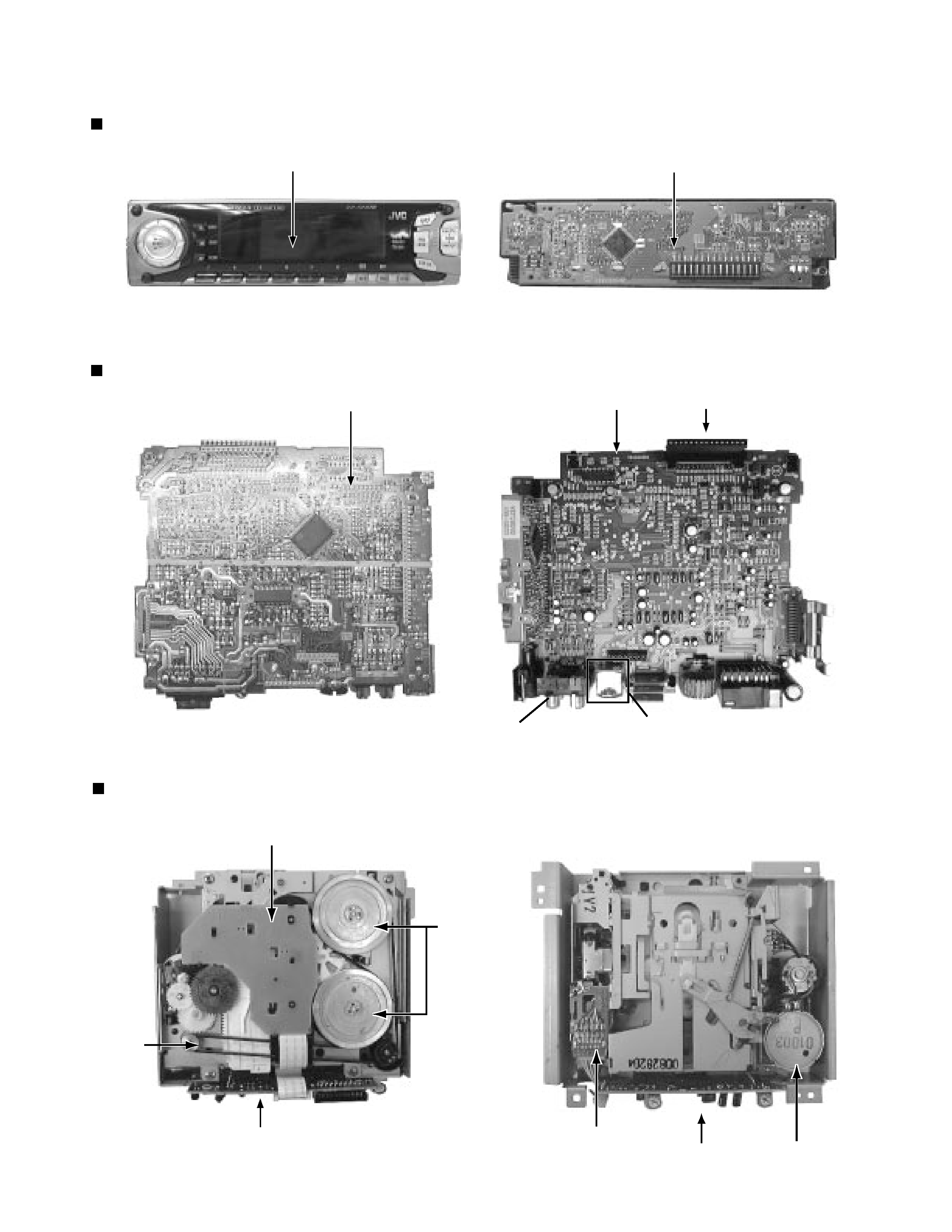
Main unit
Location of main parts
Control unit
Cassette mechanism
Display
LCD & Key control board
Main board assembly
Main board assembly
ISO connector
Mecha control board
Mecha control board
Head relay board
Capstan
motor
unit
Capstan motor unit
Pin jack
CD changer input jack
Fly wheel
Reel board
KS-FX470
1-4
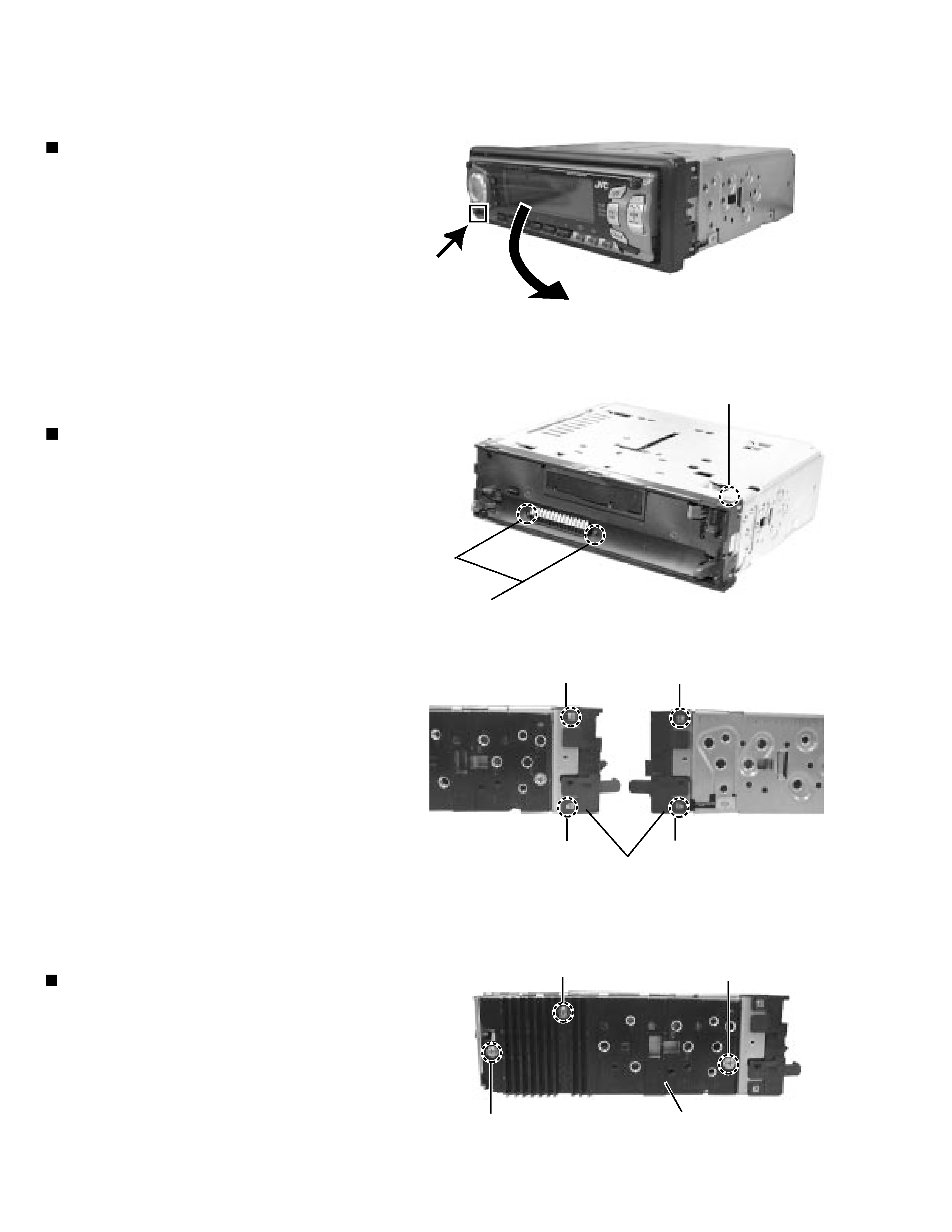
Disassembly method
Removing the front panel unit
(See Fig.1)
1.
2.
Remove the two screws A attaching the front
chassis.
Insert a screwdriver to the two joints a on the side
of the front chassis, two joints b on the right side
and one joint c from upside, then detach the front
chassis toward the front side.
1. Press the release switch and remove the front
panel unit in the direction of the arrow.
Removing the front chassis (See Fig.2~3)
Removing the heat sink (See Fig.4)
1. Remove the three screws B attaching the heat sink
on the left side of the body, and remove the heat
sink.
b
a
a
b
c
A
B
B
B
Heat sink
Fig.2
Fig.1
Fig. 3
Fig. 4
Front chassis
KS-FX470
1-5
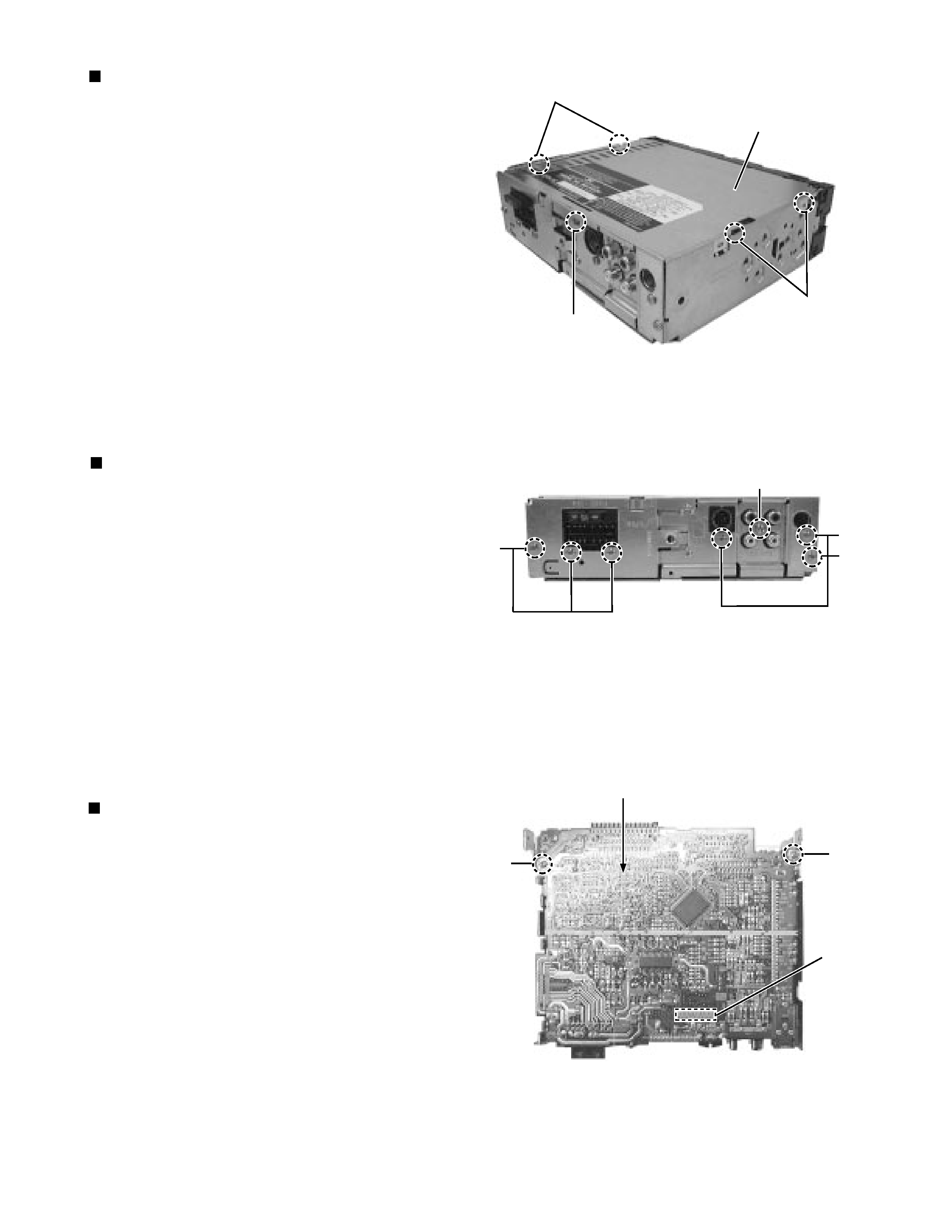
Removing the bottom cover (See Fig.5)
1.
2.
Turn the body upside down.
Insert a screwdriver to the two joints d and two
joints e on both sides of the body and the joint f on
the back of the body, then detach the bottom cover
from the body.
Removing the rear panel (See Fig.6 )
1.
2.
3.
4.
Remoe the front chassis.
Remove the heat sink.
Remove the bottom cover.
Remove the six screws B attaching the rear panel
and one screw C attaching the pine jack on the
back of the body.
Removing the main amplifier board
assembly
(See Fig.7)
1.
2.
3.
4.
5.
Remove the front chassis.
Remove the bottom cover.
Remove the rear panel.
Remove the two screws D attaching the main
amplifier board assembly on the top cover.
Disconnect connector CP701 on the main amplifier
board assembly from the cassette mechanism
assembly.
d
e
f
Bottom cover
Fig. 5
Fig. 6
Fig. 7
B
C
B
B
D
D
CP701
Main board assembly