SERVICE MANUAL
COPYRIGHT © 2003 VICTOR COMPANY OF JAPAN, LTD.
No.49828
2003/4
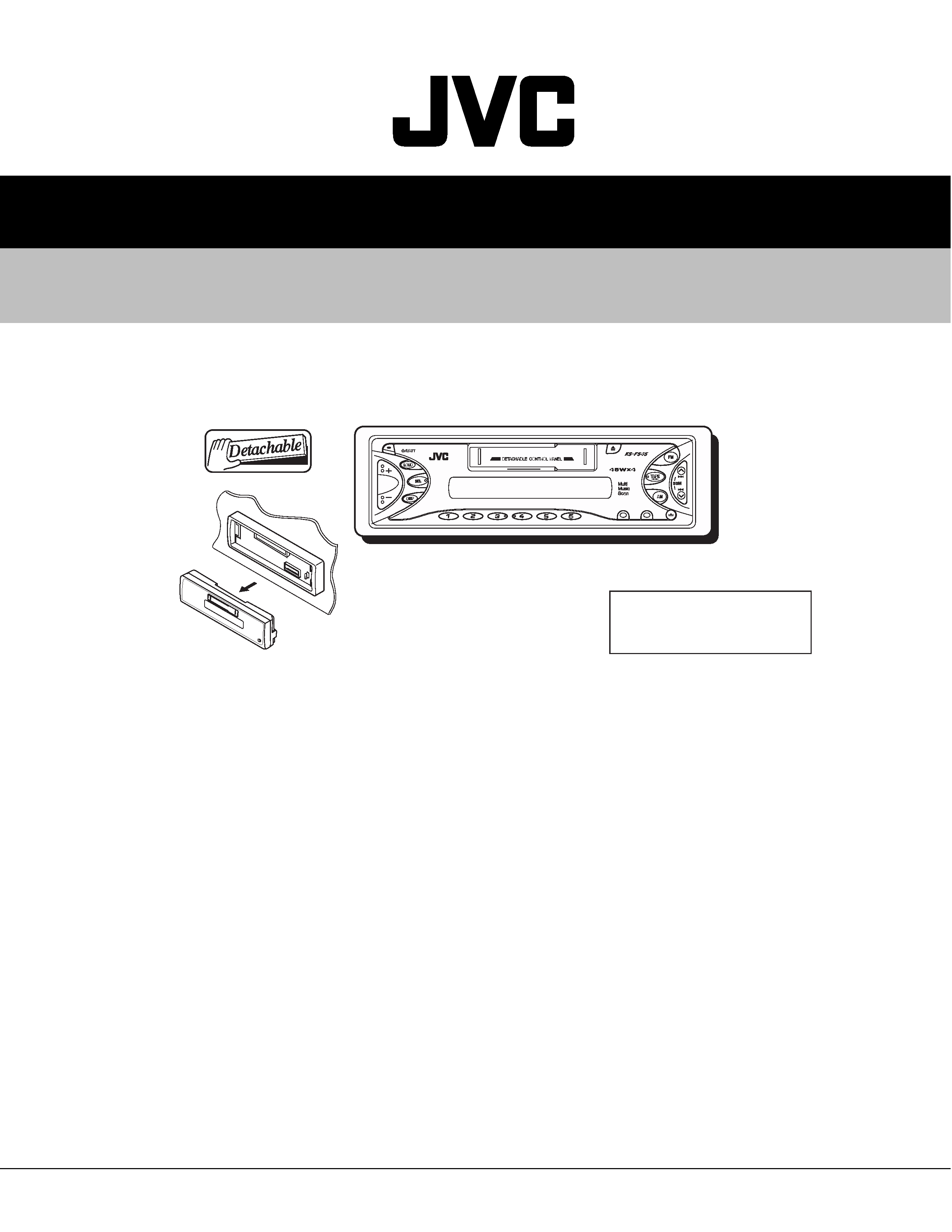
KS-F545
CASSETTE RECEIVER
49828
2003
4
KS-F545
TABLE OF CONTENTS
1
Important Safety Precautions . . . . . . . . . . . . . . . . . . . . . . . . . . . . . . . . . . . . . . . . . . . . . . . . . . . . . . . . . . . 1-2
2
Disassembly method . . . . . . . . . . . . . . . . . . . . . . . . . . . . . . . . . . . . . . . . . . . . . . . . . . . . . . . . . . . . . . . . . . 1-3
3
Adjustment. . . . . . . . . . . . . . . . . . . . . . . . . . . . . . . . . . . . . . . . . . . . . . . . . . . . . . . . . . . . . . . . . . . . . . . . . . 1-18
4
Description of major ICs. . . . . . . . . . . . . . . . . . . . . . . . . . . . . . . . . . . . . . . . . . . . . . . . . . . . . . . . . . . . . . . 1-22
MODE
SCM
MO
RPT
Area Suffix
EE ------- Russian Federation
KS-F545
1-2 (No.49828)
SECTION 1
Important Safety Precautions
1.1 Safety Precautions
!
Burrs formed during molding may be left over on some parts of the chassis. Therefore,
pay attention to such burrs in the case of preforming repair of this system.
KS-F545
(No.49828)1-3
SECTION 2
Disassembly method
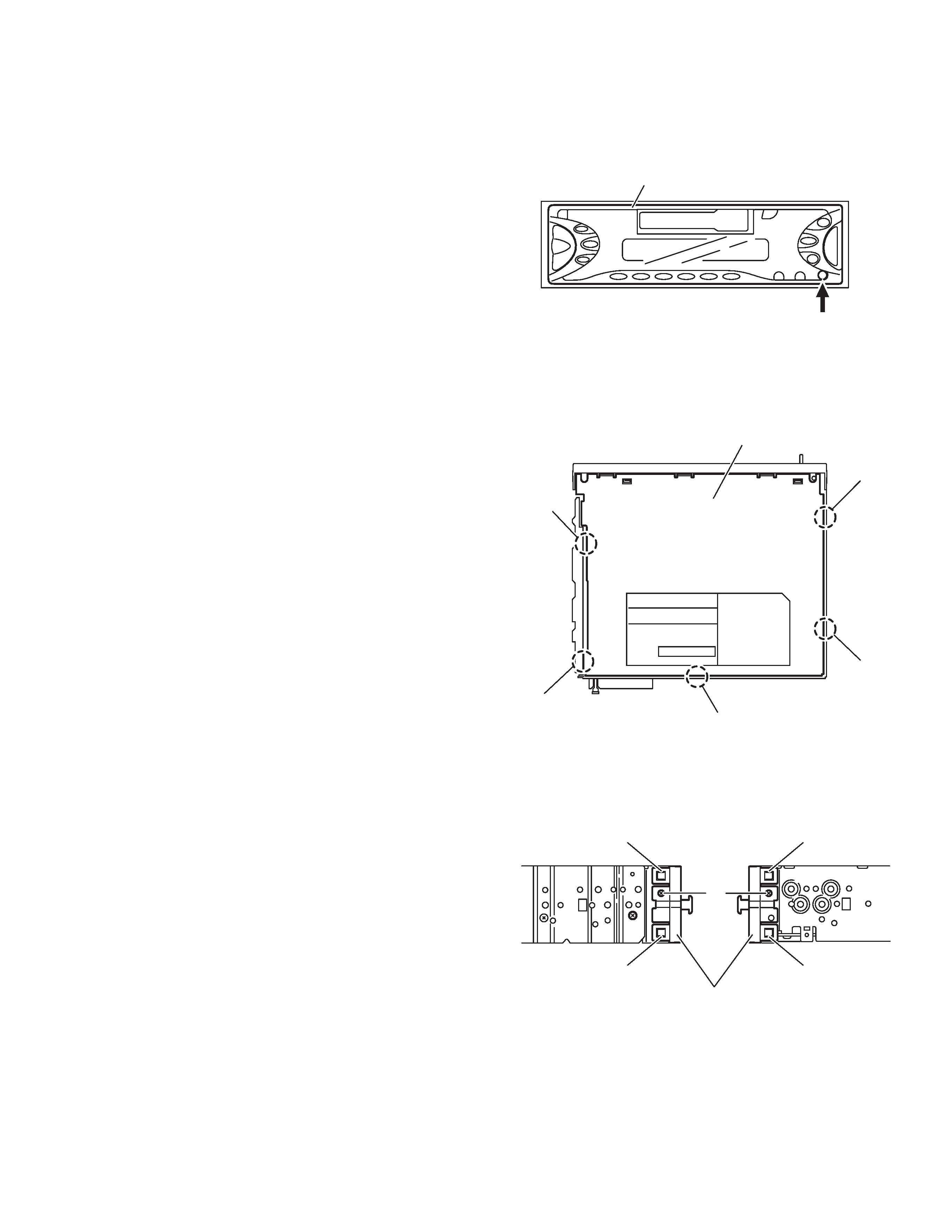
2.1 Main body
2.1.1 Removing the front panel assembly
(See Fig.1)
(1) Press the release button and remove the front panel as-
sembly.
Fig.1
2.1.2 Removing the bottom cover
(See Fig.2)
(1) Turn the main body upside down.
(2) Insert a screwdriver under the joints to release the two
joints a on the left side, two joints b on the right side and
joint c on the back side of the main body, then remove the
bottom cover from the main body.
CAUTION:
When releasing the joints using a screwdriver, do not damage
the main board.
Fig.2
2.1.3 Removing the front chassis
(See Fig.3)
· Prior to performing the following procedures, remove the front
panel assembly and bottom cover.
(1) Remove the screw A on the both sides of the main body.
(2) Release the two joints d and two joints e on the both sides
of the main body, then remove the front chassis toward the
front.
Fig.3
Front panel assembly
Release button
Bottom cover
Joint b
Joint b
Joint c
Joint a
Joint a
Joint d
Joint e
Front chassis
Joint d
A
Joint e
KS-F545
1-4 (No.49828)
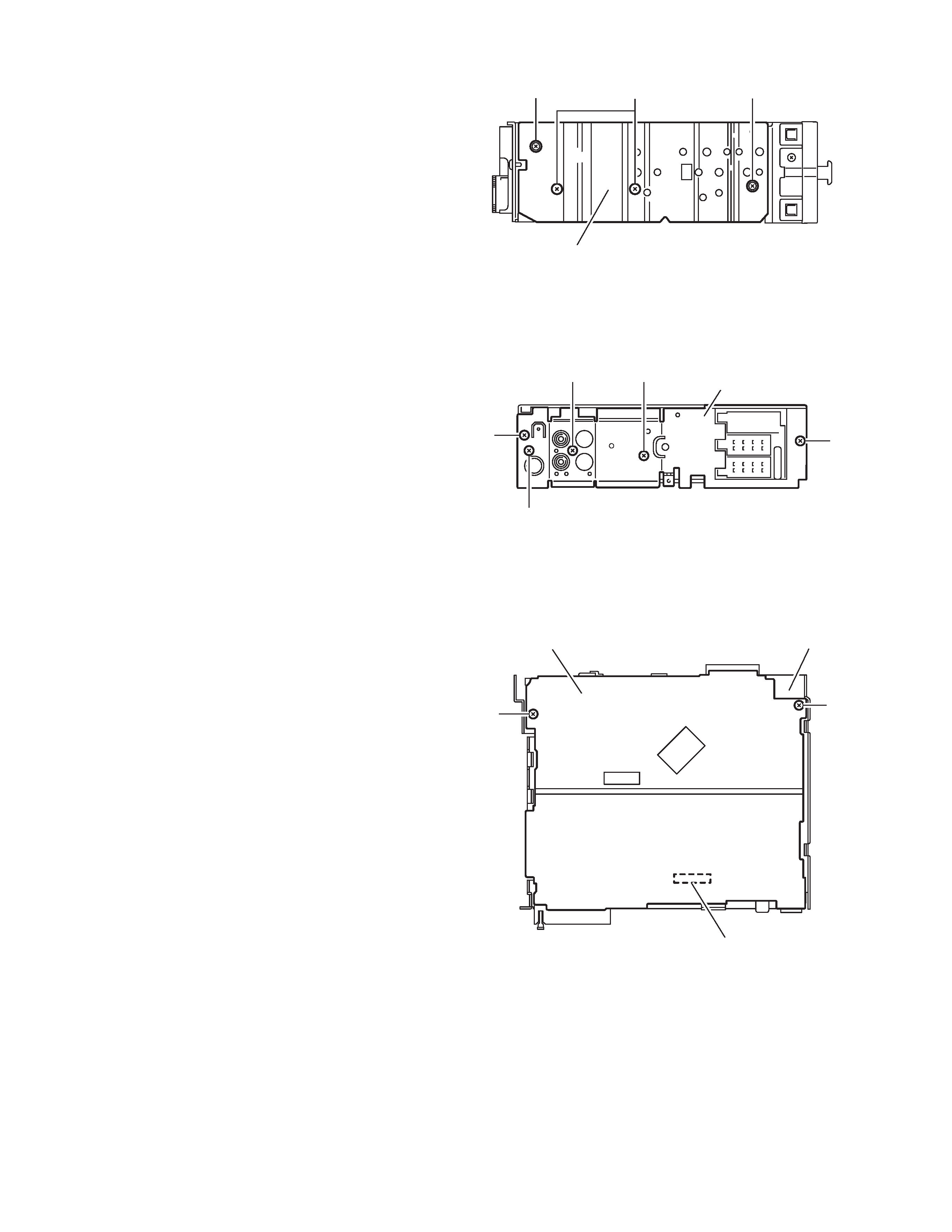
2.1.4 Removing the heat sink
(See Fig.4)
· Prior to performing the following procedure, remove the front
panel assembly.
(1) Remove the two screws B and two screws C attaching the
heat sink on the left side of the main body, and remove the
heat sink.
Fig.4
2.1.5 Removing the rear panel
(See Fig.5)
· Prior to performing the following procedure, remove the front
panel assembly and bottom cover.
(1) Remove the two screws D, two screws E and screw F at-
taching the rear panel on the back side of the main body.
Fig.5
2.1.6 Removing the main board
(See Fig.6)
· Prior to performing the following procedures, remove the front
panel assembly, bottom cover, front chassis, heat sink and
rear panel.
(1) Remove the two screws G attaching the main board on the
top chassis.
(2) Disconnect the connectors CP401 on the main board from
the cassette mechanism assembly.
Fig.6
Heat sink
CB
C
D
D
E
F
E
Rear panel
G
G
Main board
CP401
Top chassis
KS-F545
(No.49828)1-5
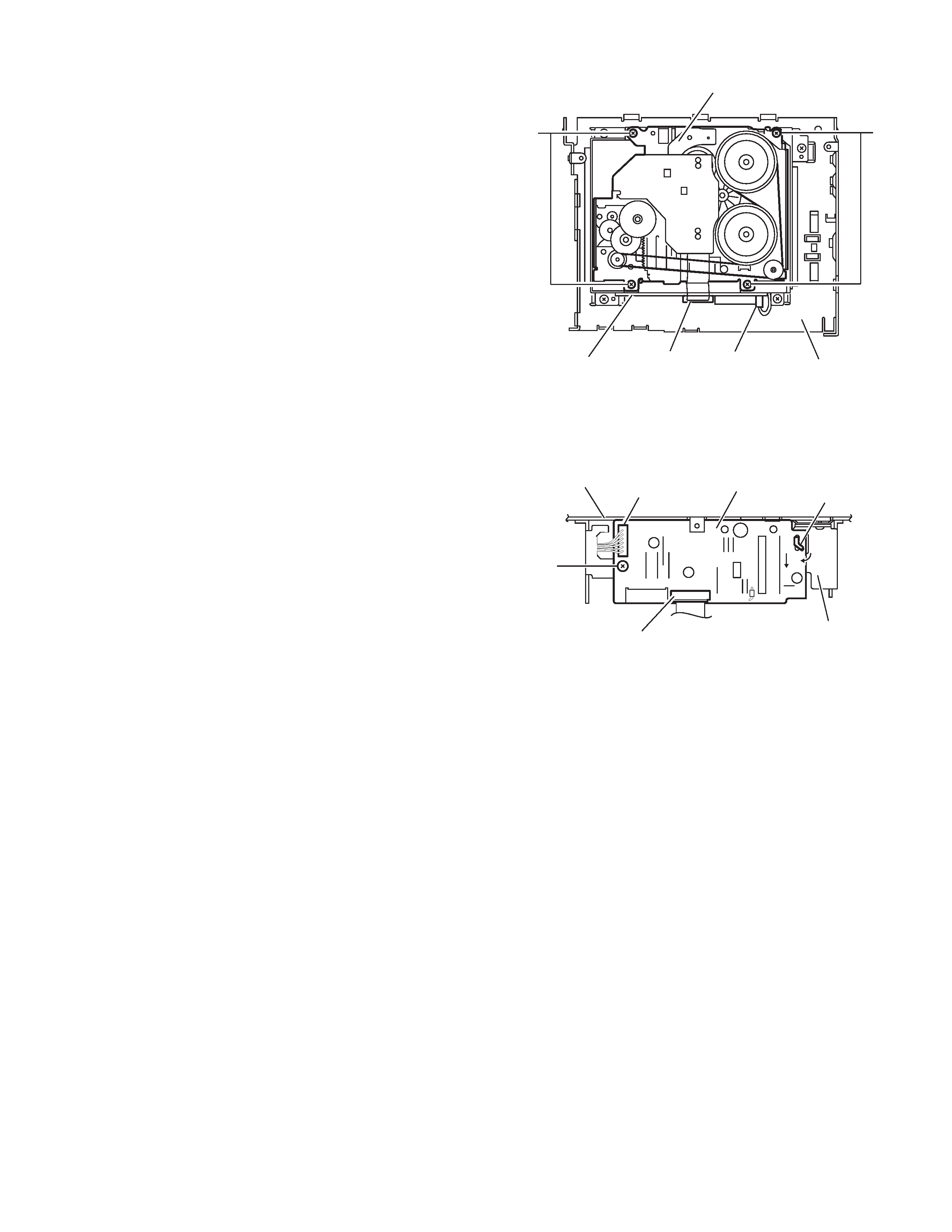
2.1.7 Removing the cassette mechanism assembly
(See Fig.7)
· Prior to performing the following procedures, remove the front
panel assembly, bottom cover, front chassis, heat sink, rear
panel and main board.
(1) Disconnect the wire from the connector CN402 on the
mecha board.
(2) Disconnect the card wire from the connector CN403 on the
mecha board.
(3) Remove the four screws H attaching the cassette mecha-
nism assembly from the top chassis.
Fig.7
2.1.8 Removing the mecha board
(See Fig.8)
· Prior to performing the following procedures, remove the front
panel assembly, bottom cover, front chassis, heat sink, rear
panel and main board.
(1) Disconnect the wire from the connector CN402 on the
mecha board.
(2) Disconnect the card wire from the connector CN403 on the
mecha board.
(3) Remove the screw J attaching the mecha board.
(4) Bend the hook f in the direction of the arrow 1 and move the
mecha board in the direction of the arrow 2.
(5) Remove the mecha board from the mecha bracket (L) of
the top chassis.
Fig.8
H
H
Top chassis
Cassette mechanism assembly
CN403
CN402
Mecha board
J
Mecha board
Hook f
Top chassis
Mecha bracket (L)
CN402
CN403
1
2