SERVICE MANUAL
COPYRIGHT © 2005 Victor Company of Japan, Limited
No.MA194
2005/9
POWER AMPLIFIER
MA194
2005
9
KS-AX5500
Lead free solder used in the board (material : Sn-Ag-Cu, melting point : 219 Centigrade)
TABLE OF CONTENTS
1
PRECAUTION. . . . . . . . . . . . . . . . . . . . . . . . . . . . . . . . . . . . . . . . . . . . . . . . . . . . . . . . . . . . . . . . . . . . . . . . . 1-2
2
SPECIFIC SERVICE INSTRUCTIONS . . . . . . . . . . . . . . . . . . . . . . . . . . . . . . . . . . . . . . . . . . . . . . . . . . . . . . 1-2
3
DISASSEMBLY . . . . . . . . . . . . . . . . . . . . . . . . . . . . . . . . . . . . . . . . . . . . . . . . . . . . . . . . . . . . . . . . . . . . . . . 1-3
4
ADJUSTMENT . . . . . . . . . . . . . . . . . . . . . . . . . . . . . . . . . . . . . . . . . . . . . . . . . . . . . . . . . . . . . . . . . . . . . . . . 1-7
5
TROUBLESHOOTING . . . . . . . . . . . . . . . . . . . . . . . . . . . . . . . . . . . . . . . . . . . . . . . . . . . . . . . . . . . . . . . . . . 1-9
Area suffix
J ------------- Northern America
E ------------- Southern Europe
U -------------------- Other Areas
1-2 (No.MA194)
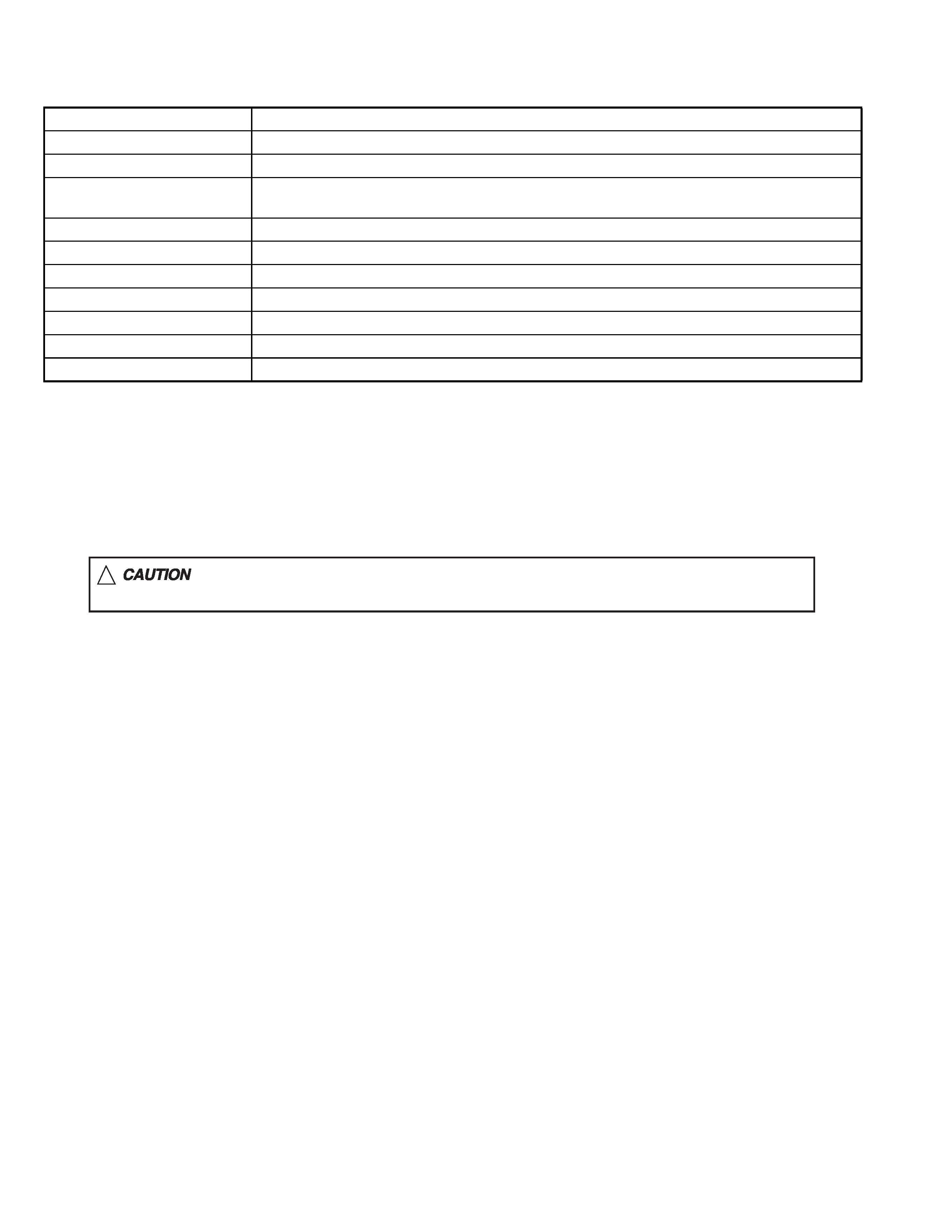
SPECIFICATION
Design and specifi cations are subject to change without notice.
SECTION 1
PRECAUTION
1.1
Safety Precautions
SECTION 2
SPECIFIC SERVICE INSTRUCTIONS
This service manual does not describe SPECIFIC SERVICE INSTRUCTIONS.
Power Output
100 W RMS
× 4 channels at 4 and [ < or = ] 1% THD + N
Signal-to-Noise Ratio
80 dBA (reference: 1 W into 4
)
Maximum Power Output
800 W
Load Impedance
4
(2 to 8 allowance)
4
(4 to 8 allowance) (Bridge mode)
Frequency Response
5 Hz to 50,000 Hz ( +0, -3 dB)
Input Sensitivity/Impedance
1 V/20 k
(0.3 V to 6 V, variable)
Distortion
Less than 0.004% (at 1 kHz)
Power Requirement
DC 14.4 V (11 V to 16 V allowance)
Grounding system
Negative ground
Dimensions (W/H/D)
400 mm
× 264 mm × 63 mm (15-3/4 in. × 10-7/16 in. × 2-1/2 in.)
Mass (approx.)
5.7 kg (12.6 lbs.)
!
Burrs formed during molding may be left over on some parts of the chassis. Therefore,
pay attention to such burrs in the case of preforming repair of this system.
(No.MA194)1-3
SECTION 3
DISASSEMBLY
3.1
Main body
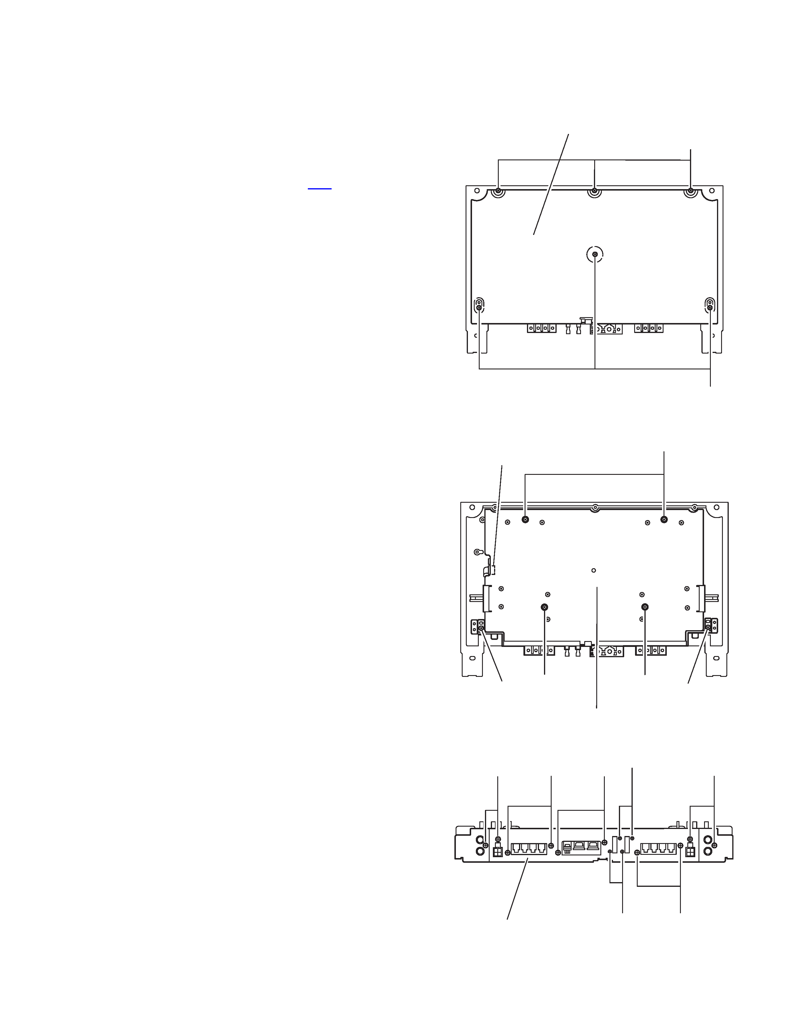
3.1.1 Removing the main board (See Fig.1 to 3)
(1) From the bottom of the body, remove the six screws A at-
taching the cover.
(2) Disconnect the wire from connector CN2 on the main
board.
(3) Remove the four screws B, the two screws D attaching the
main board.
(4) From the front side of the body, remove the ten screws E
and the four screws F attaching the cover.
Fig.1
Fig.2
Fig.3
A
A
Cover
B
B
B
DD
CN2
Main board
EE
E
F
F
EE
Rear cover
1-4 (No.MA194)
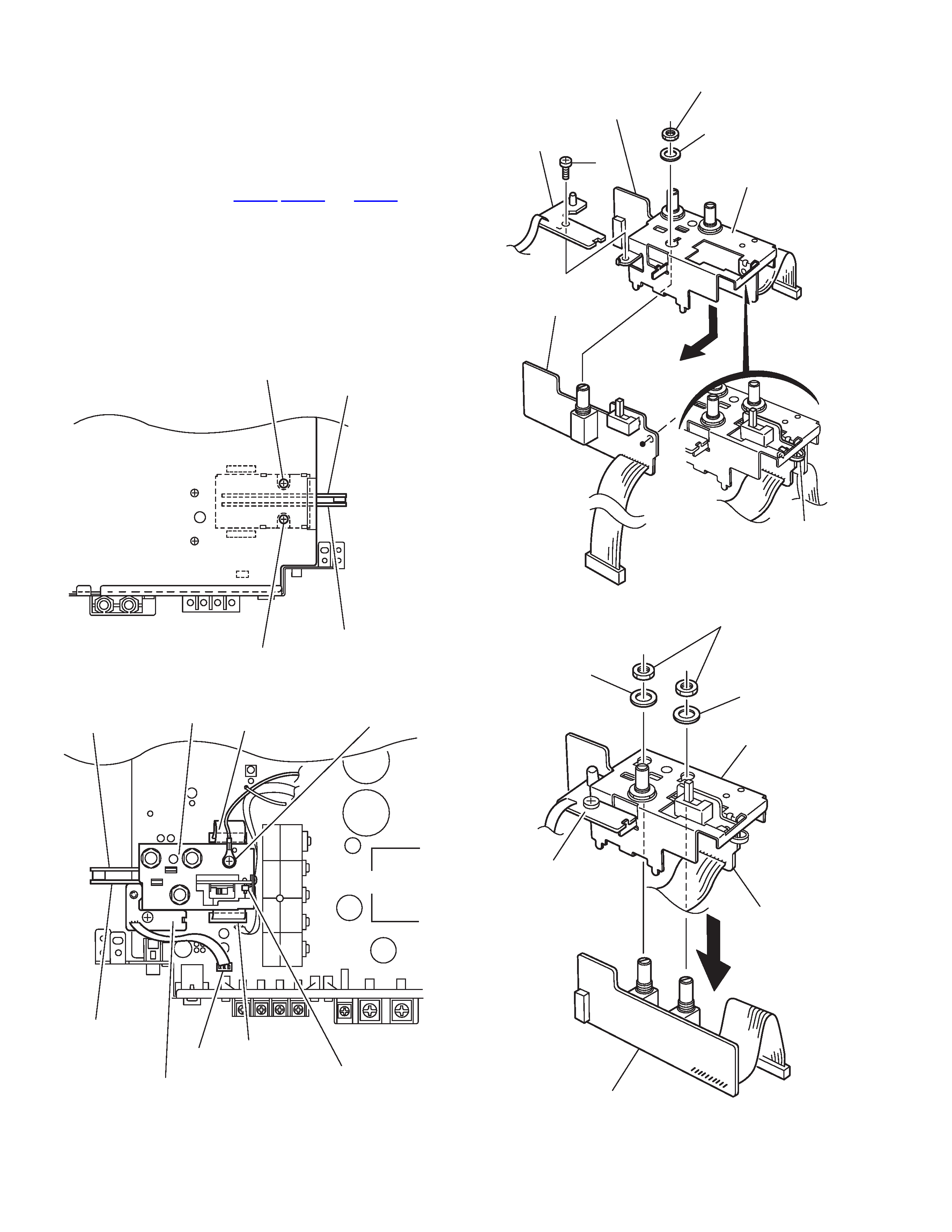
3.1.2 Removing the cross over A board, the bass boost A
board and the LED A board (See Fig. 4 to 7)
· Prior to performing the following procedure, remove the main
board.
(1) From the bottom of the main board, remove the two screws
G attaching the bracket.
(2) Remove the screw H and disconnect the wire.
(3) Disconnect the wire from CN504,CN505 and CN591 on the
main board. Remove the cross over A board and the bass
boost A board with the bracket.
(4) Remove the band, the washer and the nut from the cross
over A board.
(5) Remove the washer and nut from the bass boost A board.
(6) Remove the screw J attaching the LED A board.
Attention:
You can remove the LED A board only from the main board.
Fig.4
Fig.5
Fig.6
Fig.7
G
G
Main board
Bass boost A board
Cross over A board
H
CN591
CN504
CN505
Main board
Bass boost A
board
Cross over A
board
LED A board
Bracket
Band
J
Nat
Washer
Bracket
Cross over A board
Bass boost A board
LED A board
Band
Nat
Washer
Washer
Bracket
Cross over A
board
Bass boost A board
LED A board
(No.MA194)1-5
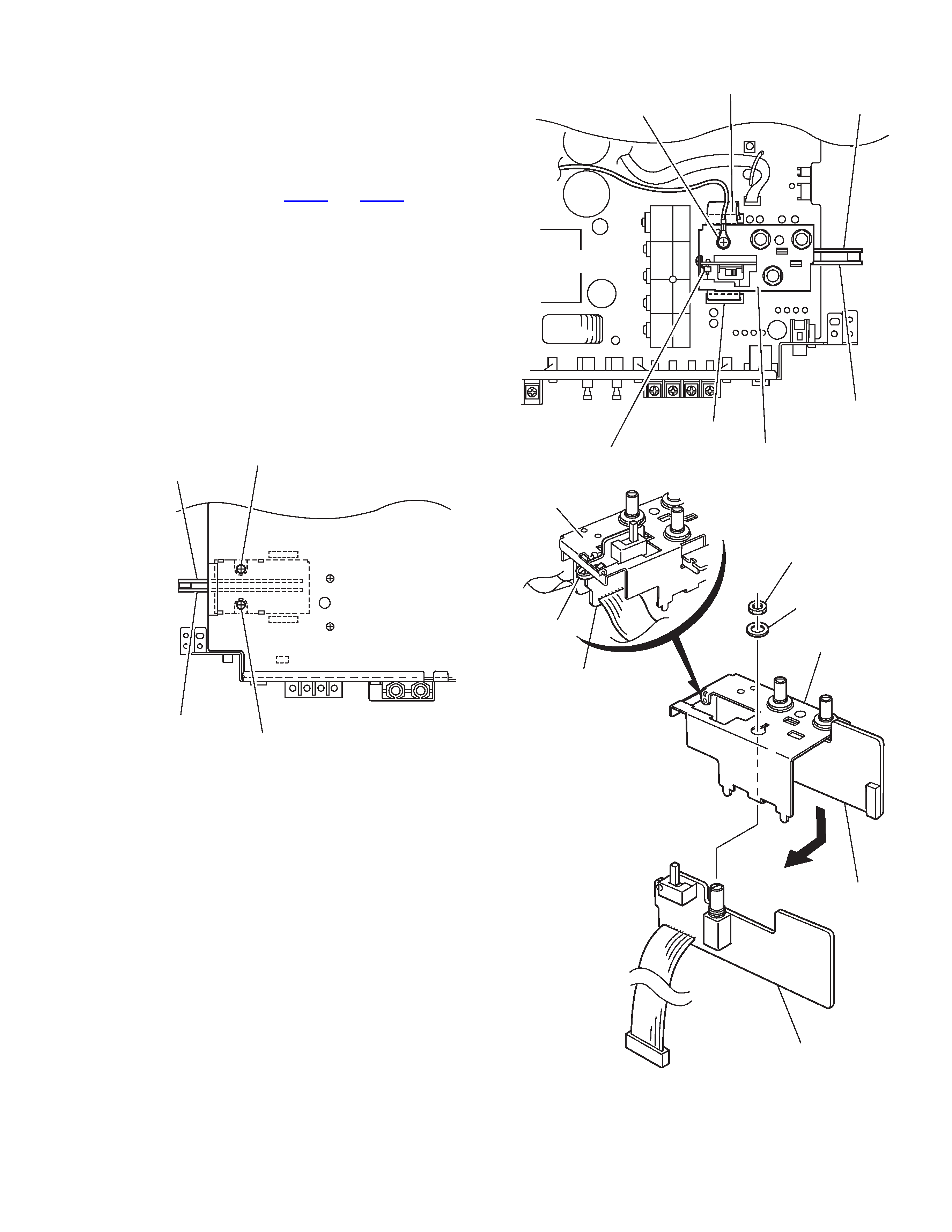
3.1.3 Removing the cross over C board and the cross over
B board (See Fig. 8 to 11)
· Prior to performing the following procedure, remove the main
board.
(1) From the bottom of the main board, remove the two screws
K attaching the bracket.
(2) Remove the screw M and disconnect the wire.
(3) Disconnect the wire from CN704 and CN705 on the main
board. Remove the cross over B board and the cross over
C board with the bracket.
(4) Remove the band, the washer and the nut from the cross
over C board.
(5) Remove the washer and nut from the cross over B board.
3.1.4 Removing the LED B board and the bass boost B
board (See Fig.12, 13)
· Prior to performing the following procedure, remove the main
board.
(1) Remove the two screws N attaching the LED B board and
the bass boost B board.
(2) Remove the two screws P attaching the LED B board and
the bass boost B board.
Fig.8
Fig.9
Fig.10
K
K
Main board
Cross over B board
Cross over C board
CN704
CN705
Bracket
Band
Cross over B
board
Cross over C
board
M
Main board
Nat
Washer
Bracket
Bracket
Cross over B
board
Cross over C board
Cross over C board
Band