INSTRUCTIONS
SCAN RATE CONVERTER
KM-F700
For Customer Use:
Enter below the Serial No. which is
located on the bottom of cabinet. Retain
this information for future reference.
Model No.
KM-F700
Serial No.
SC96987
R
CONTROLS, INDICATORS
AND CONNECTORS
CONNECTION EXAMPLES
AND OPERATIONS
OTHERS
SCAN R
ATE CON
VERTER
KM-F700
POWER
AUTO W
HITE
SEND
FREEZE
is a registered trademark owned by VICTOR COMPANY OF JAPAN, LTD.
is a registered trademark in Japan, the U.S.A., the U.K. and many other countries.
© 2000 VICTOR COMPANY OF JAPAN, LIMITED
KM-F700
SCAN
RATE
CONVERTER
Printed in Japan
SC96987
VICTOR COMPANY OF JAPAN, LIMITED
R
E-3
CAUTION: TO REDUCE THE RISK OF ELECTRIC SHOCK,
DO NOT REMOVE COVER (OR BACK).
NO USER SERVICEABLE PARTS INSIDE.
REFER SERVICING TO QUALIFIED SERVICE
PERSONNEL.
Information for USA
This device complies with Part 15 of the FCC Rules.
Changes or modifications not approved by JVC could
void the user's authority to operate the equipment.
The lightning flash with arrowhead symbol,
within an equilateral triangle is intended to
alert the user to the presence of uninsulated
"dangerous voltage" within the product's en-
closure that may be of sufficient magnitude
to constitute a risk of electric shock to per-
sons.
The exclamation point within an equilateral
triangle is intended to alert the user to the
presence of important operating and main-
tenance (servicing) instructions in the litera-
ture accompanying the appliance.
WARNING:
TO REDUCE THE RISK OF FIRE OR ELEC-
TRIC SHOCK, DO NOT EXPOSE THIS APPLI-
ANCE TO RAIN OR MOISTURE.
This unit should be used with 12V DC only.
CAUTION:
To prevent electric shocks and fire hazards, do NOT use
any other power source.
Changes or modifications not approved by JVC could void
the user's authority to operate the equipment.
This unit is designed for professional use only.
INFORMATION (FOR CANADA)
RENSEIGNEMENT (POUR CANADA)
This Class B digital apparatus complies with Canadian
ICES-003.
Cet appareil numérique de la classe B est conforme à
la norme NMB-003 du Canada.
SAFETY PRECAUTIONS
CAUTION
RISK OF ELECTRIC SHOCK
DO NOT OPEN
FOR USA AND CANADA
CAUTION:
To prevent electric shock, do not open the cabinet. No
user serviceable parts inside. Refer servicing to qualified
service personnel.
Due to design modifications, data given in this in-
struction book are subject to possible change with-
out prior notice.
This unit converts video signals from KY-F70/KY-F70B Dig-
ital cameras into 7.5 frames/sec. to 75 frames/sec. signals
so that high-resolution semi-movie signals can be displayed
on an SXGA-compatible monitor.
Some features on KY-F70/KY-F70B Digital cameras can be
controlled remotely using this KM-F700 unit. (FREEZE,
AUTO WHITE BALANCE and SEND operations).
The Camera Remote connection function is distributed to
the connector on the rear panel, so as to be used as the
terminal box for the camera control.
FEATURES
Thank you for purchasing this JVC product.
Before operating this unit, please read the instructions
carefully to ensure the best possible performance.
When this unit is not used for an extended period of
time, make sure that the system power is turned off in
order to save energy.
These instructions are for KM-F700U.
1. CONTROLS, INDICATORS AND CONNECTORS
1-1 Front Panel .............................................................. 4
1-2 Rear Panel ............................................................... 5
2. CONNECTION EXAMPLES AND OPERATIONS
2-1 To Input Camera Images .......................................... 6
2-2 To Shoot Using an External Switch .......................... 7
2-3 To Extend the Camera Cable (KY-F70B only) .......... 8
CONTENTS
3. OTHERS
3-1 Pin Configuration ..................................................... 9
3-2 Troubleshooting ..................................................... 10
3-3 Specifications .......................................................... 11
Characters and symbols used in this INSTRUCTION MANUAL
CAUTION .......... Cautionary notes concerning operation of the unit.
MEMO ............... Reference such as restrictions of featuers, etc.
..................... Reference page or item.
E-2
1. Read all of these instructions.
2. Save these instructions for later use.
3. All warnings on the product and in the operating instructions should be adhered to.
4. Unplug this appliance system from the wall outlet before cleaning. Do not use liquid cleaners or aerosol cleaners. Use a
damp cloth for cleaning.
5. Do not use attachments not recommended by the appliance manufacturer as they may cause hazards.
6. Do not use this appliance near water for example, near a bathtub, washbowl, kitchen sink, or laundry tub, in a wet
basement, or near a swimming pool, etc.
PORTABLE CART WARNING
(symbol provided by RETAC)
S3126A
IMPORTANT SAFEGUARDS
7. Do not place this appliance on an unstable cart, stand, or table. The appliance may fall, causing
serious injury to a child or adult, and serious damage to the appliance.
Use only with a cart or stand recommended by the manufacturer, or sold with the appliance. Wall or
shelf mounting should follow the manufacturer's instructions, and should use a mounting kit
approved by the manufacturer.
An appliance and cart combination should be moved with care. Quick stops, excessive force, and
uneven surfaces may cause the appliance and cart combination to overturn.
8. Slots and openings in the cabinet and the back or bottom are provided for ventilation, and to insure reliable operation of the
appliance and to protect it from overheating, these openings must not be blocked or covered. The openings should never be
blocked by placing the appliance on a bed, sofa, rug, or other similar surface. This appliance should never be placed near or
over a radiator or heat register. This appliance should not be placed in a built-in installation such as a bookcase unless proper
ventilation is provided.
9. This appliance should be operated only from the type of power source indicated on the marking label. If you are not sure of
the type of power supplied to your home, consult your dealer or local power company. For appliance designed to operate
from battery power, refer to the operating instructions.
10. This appliance system is equipped with a 3-wire grounding type plug (a plug having a third (grounding) pin). This plug will only
fit into a grounding-type power outlet. This is a safety feature. If you are unable to insert the plug into the outlet, contact your
electrician to replace your obsolete outlet. Do not defeat the safety purpose of the grounding plug.
11. For added protection for this product during a lightning storm, or when it is left unattended and unused for long periods of
time, unplug it from the wall outlet and disconnect the antenna or cable system. This will prevent damage to the product due
to lightning and power-line surges.
12. Do not allow anything to rest on the power cord. Do not locate this appliance where the cord will be abused by persons
walking on it.
13. Follow all warnings and instructions marked on the appliance.
14. Do not overload wall outlets and extension cords as this can result in fire or electric shock.
15. Never push objects of any kind into this appliance through cabinet slots as they may touch dangerous voltage points or short
out parts that could result in a fire or electric shock. Never spill liquid of any kind on the appliance.
16. Do not attempt to service this appliance yourself as opening or removing covers may expose you to dangerous voltage or
other hazards. Refer all servicing to qualified service personnel.
17. Unplug this appliance from the wall outlet and refer servicing to qualified service personnel under the following conditions:
a. When the power cord or plug is damaged or frayed.
b. If liquid has been spilled into the appliance.
c. If the appliance has been exposed to rain or water.
d. If the appliance does not operate normally by following the operating instructions. Adjust only those controls that are
covered by the operating instructions as improper adjustment of other controls may result in damage and will often require
extensive work by a qualified technician to restore the appliance to normal operation.
e. If the appliance has been dropped or the cabinet has been damaged.
f. When the appliance exhibits a distinct change in performance this indicates a need for service.
18. When replacement parts are required, be sure the service technician has used replacement parts specified by the manufac-
turer that have the same characteristics as the original part. Unauthorized substitutions may result in fire, electric shock, or
other hazards.
19. Upon completion of any service or repairs to this appliance, ask the service technician to perform routine safety checks to
determine that the appliance is in safe operating condition.
E-5
Before connection, be sure to refer to the instruction manuals of the equipment to be used.
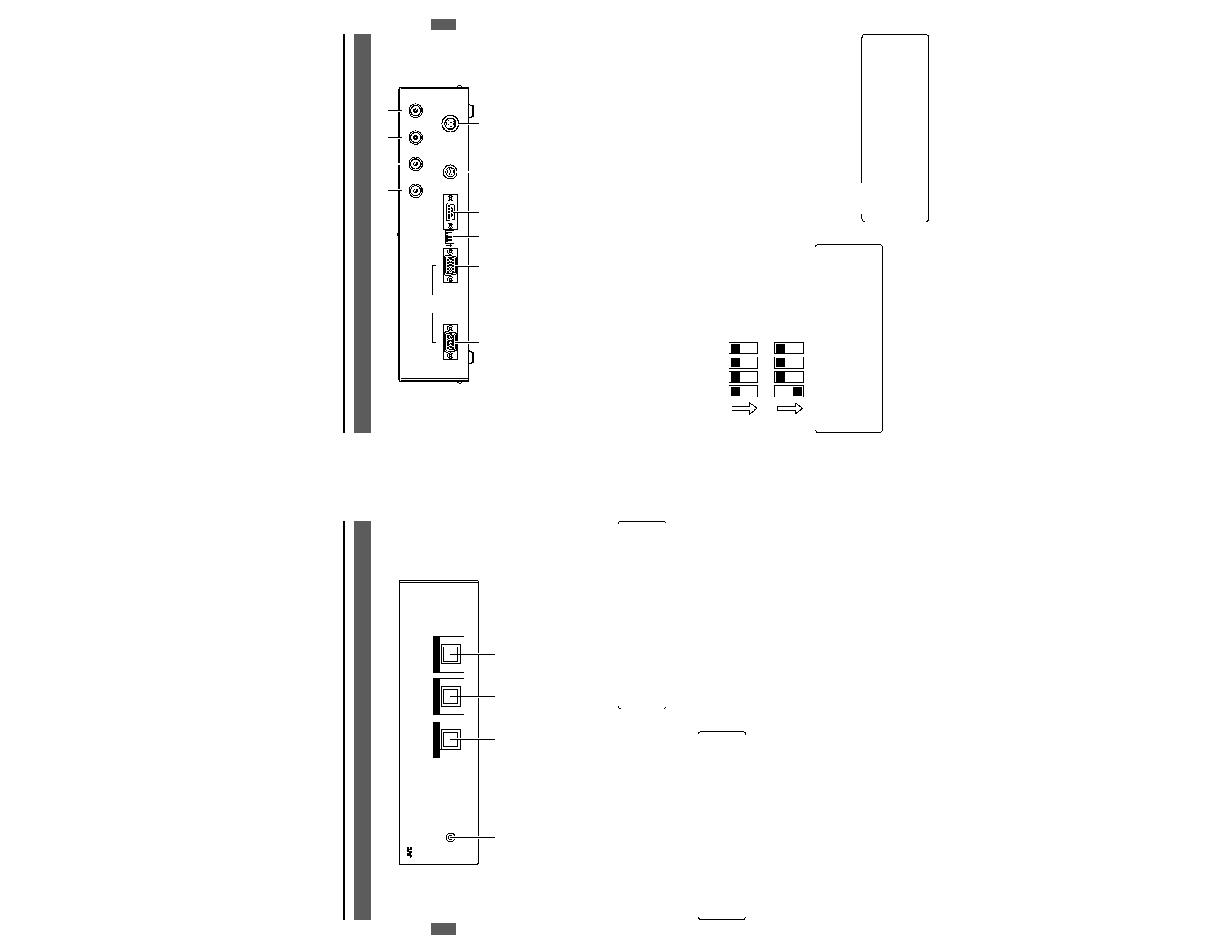
1. CONTROLS, INDICATORS AND CONNECTORS
9 [VIDEO OUTPUT] terminal
(Mini D-Sub 15-pin, female)
Connect to the video-input terminal of an SXGA-compat-
ible monitor. Note that when a sync signal from the cam-
era is not input to the
0 VIDEO INPUT terminal, no video
signal is output.
0 [VIDEO INPUT] terminal
(Mini D-Sub 15-pin, female)
Connect to the MONITOR terminal of the camera (KY-
F70/KY-F70B).
! [WEN] write enable output terminal
Outputs through the WEN (write enable) signal input to
the
6 CAMERA CTL terminal.
(For specifications and operations
KY-F70/KY-F70B
INSTRUCTION MANUAL.)
@ [FLASH] control output terminal
Connect the external flash to this unit. The FLASH signal
from the camera (KY-F70/KY-F70B) is output from here.
(For specifications and operations
KY-F70/KY-F70B
INSTRUCTION MANUAL.)
# [FREEZE] control input terminal
Used to control the freeze operation of the camera (KY-
F70/KY-F70B) using an external switch. The external switch
output signal is output to the
6 CAMERA CTL terminal.
$ [SEND] SCSI output control terminal
Used when images from the camera (KY-F70/KY-F70B)
are output to a MO/ZIP® drive or a printer using an ex-
ternal switch. The external switch output signal is output
to the
6 CAMERA CTL terminal.
1-2 Rear Panel
SEND
DC 12V IN
SEE INSTRUCTION MANUAL
CAMERA CTL
RS-232C
FREEZE
FLASH
WEN
MODE
OUTPUT
VIDEO
INPUT
!@
#
$
5
6
7
8
9
0
12
ON
34
1
ON
234
1
ON
234
Standard mode
(1280 x 1024 pixels)
Wide mode
(1360 x 1024 pixels)
5 [DC 12V IN] power input terminal
(Mini DIN 8-pin, female)
Supplies power (DC 12V) to the unit. Connect this termi-
nal to an AA-P700 AC adapter (optional) using the power
cable provided.
6 [CAMERA CTL] Camera Control
terminal
When connected to the camera (KY-F70/KY-F70B) us-
ing the provided cable, camera operations such as Auto
White Balance or Freeze can be controlled remotely.
7 [RS-232C] serial remote terminal
(D-Sub 9-pin, male)
This terminal is used when remotely controlling the cam-
era (KY-F70/KY-F70B) with a personal computer.
Use the D-sub 9 pin cross cable, which is available on the
market.
8 [MODE] select switch
Select the output screen mode with this switch.
Switches 2, 3 and 4 are not used. Leave them in OFF mode.
MEMO
When using the Wide mode with the D-ILA Projector
connected, set the CLAMP item to [ST] in the ON
SCREEN menu.
When using the Wide mode, a distorted video may be
displayed depending on which monitor is being used.
In this case use the Standard mode.
MEMO
The
7 RS-232C, ! WEN, @ FLASH, $ SEND and
# FREEZE terminals only function when the 6 CAM-
ERA CTL terminal of this unit is connected to the RE-
MOTE terminal of a KY-F70/KY-F70B camera.
Image output to ZIP® drives is only possible with KY-
F70B cameras.
E-4
1 [
POWER] display lamp
This lights up when power is supplied to the unit.
2 [
AUTO WHITE] button
Press this button to start the Auto White balance func-
tion of an attached camera (KY-F70/KY-F70B).
(Valid only when camera is in Auto White mode)
3 [
SEND] button
When a camera is in Freeze mode, press this button to
send the image to an MO/ZIP® drive or a printer.
1. CONTROLS, INDICATORS AND CONNECTORS
4 [
FREEZE] button
When this button is pressed, the image from the camera
will be in the freeze mode (Still image), pressing the but-
ton again will release it from this mode.
MEMO
Select image output equipment using the menu of the
camera (KY-F70/KY-F70B). (
page 6.)
Image output to ZIP® drives is only possible with KY-
F70B cameras.
MEMO
The 2 AUTO WHITE, 3 SEND and 4 FREEZE button
operations are available only when the 6 CAMERA CTL
terminal is connected to the REMOTE terminal of the cam-
era (KY-F70/KY-F70B).
1-1 Front Panel
SCAN RATE CONVERTER KM-F700
POWER
1
2
3
4
AUTO WHITE
SEND
FREEZE
Before connection, be sure to refer to the instruction manuals of the equipment to be used.
E-6
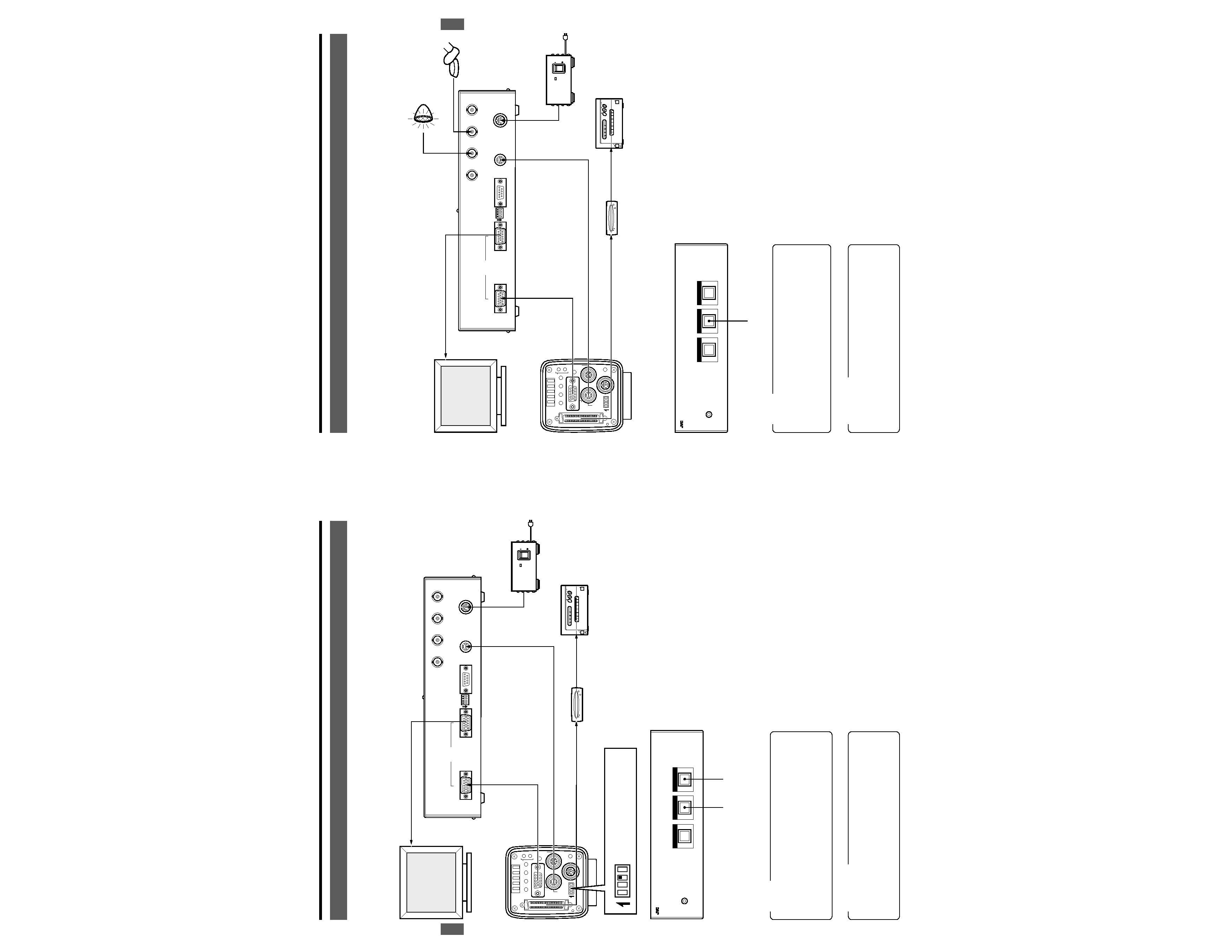
2. CONNECTION EXAMPLES AND OPERATIONS
2-1 To Input Camera Images
Monitor images from the camera (KY-F70/KY-F70B)can be stored on an MO/ZIP® drive or output to a printer.
<Connection Example>
Before connection, be sure to refer to the instruction manuals of the equipment to be used.
<Operations>
1. Check connections and set the DIP switch of the camera
(KY-F70/KY-F70B) to SXGA mode.
2. Turn on the power source to this unit and that to all con-
nected equipment except for the camera (KY-F70/KY-
F70B).
3. Turn on the power source to the camera (KY-F70/KY-
F70B).
The image from the camera (KY-F70/KY-F70B) is dis-
played on the monitor screen.
4. Perform the menu setting of the camera (KY-F70/KY-
F70B).
(
KY-F70/KY-F70B INSTRUCTION MANUAL.)
5. Set the image to be input and press the FREEZE button.
The still image is displayed on the monitor screen and
the "FREEZE" indication appears.
6. Press the SEND button to output the image on the moni-
tor screen to an MO/ZIP® drive or a printer.
Select the equipment to which the image is output us-
ing the PRIORITY setting option in the SYSTEM SET-
TING MENU of the camera (KY-F70/KY-F70B).
MEMO
Image output to ZIP® drives is only possible with KY-
F70B cameras.
Make sure that the connections to and from the VIDEO
INPUT and VIDEO OUTPUT terminals have been made
correctly.
POWER
ALARM
SHEET
PAPER
DATA
OPEN
CP700DSA
MITSUBISHI
ONLINE
COPY
& CUT
PAPER FEED
]
VIDEO OUTPUT
SXGA-compatible Monitor
VIDEO INPUT
MONITOR
REMOTE
SCSI
CAMERA CTL
DC12V IN
AC ADAPTER AA-P700
ON
OFF
POWER
AA-P700
MO drive
Printer
AC Adapter
AC
SEE INSTRUCTION MANUAL
POWER
DC IN
REMOTE
MONITOR
LENS
FREEZE
PLAY
SET
DOWN
AW/SEL
SEND
SCSI
UP
MENU
MODE
REC
ON 1 2 3 4
KY-F70/KY-F70B
ON 1 2 3 4
6.
5.
1. For SXGA mode, set the
pin 3 to ON.
SCAN RATE CONVERTER KM-F700
POWER
AUTO WHITE
SEND
FREEZE
SEND
DC 12V IN
SEE INSTRUCTION MANUAL
CAMERA CTL
RS-232C
FREEZE
FLASH
WEN
MODE
OUTPUT
VIDEO
INPUT
12
ON
34
CAUTIONS
Be sure to use an AA-P700 AC adapter (optional) as
the power source for this unit.
Make sure that the power supply to all equipment is
turned off before making connections.
E-7
2. CONNECTION EXAMPLES AND OPERATIONS
2-2 To Shoot Using an External Switch
An external switch can be used to capture still images from the camera (KY-F70/KY-F70B). When this switch is activated a flash
lights up to indicate that the image has been captured.
<Connection Example>
Before connection, be sure to refer to the instruction manuals of the equipment to be used.
<Operations>
1. Check connections and set the DIP switch of the camera
(KY-F70/KY-F70B) to SXGA mode.
2. Turn on the power source to this unit and that to all con-
nected equipment except for the camera. (KY-F70/KY-
F70B)
3. Turn on the power source to the camera. (KY-F70/KY-
F70B)
The image from the camera (KY-F70/KY-F70B) is dis-
played on the monitor screen.
4. Set the menu settings of the camera (KY-F70/KY-F70B).
(
KY-F70/KY-F70B INSTRUCTION MANUAL.)
5. Set the image to be input and press the external switch.
A flash, lights up and the still image is displayed in the
monitor screen together with the indicator "FREEZE".
6. Press the SEND button to output the image on the moni-
tor screen to an MO/ZIP® drive or a printer.
Select the equipment to which the image is output us-
ing the PRIORITY setting option in the SYSTEM SET-
TING MENU of the camera (KY-F70/KY-F70B).
MEMO
Image output to ZIP® drives is only possible with KY-
F70B cameras.
Make sure that the connections to and from the VIDEO
INPUT and VIDEO OUTPUT terminals have been made
correctly.
CAUTIONS
Be sure to use an AA-P700 AC adapter (optional) as
the power source for this unit.
Make sure that the power supply to all equipment is
turned off before making connections.
POWER
ALARM
SHEET
PAPER
DATA
OPEN
CP700DSA
MITSUBISHI
ONLINE
COPY
& CUT
PAPER FEED
]
VIDEO OUTPUT
SXGA-compatible Monitor
VIDEO INPUT
MONITOR
REMOTE
SCSI
CAMERA CTL
DC12V IN
AC ADAPTER AA-P700
ON
OFF
POWER
AA-P700
MO drive
Printer
Flash
External switch
AC
SEE INSTRUCTION MANUAL
POWER
DC IN
REMOTE
MONITOR
LENS
FREEZE
PLAY
SET
DOWN
AW/SEL
SEND
SCSI
UP
MENU
MODE
REC
ON 1 2 3 4
KY-F70/KY-F70B
6.
AC Adapter
SCAN RATE CONVERTER KM-F700
POWER
AUTO WHITE
SEND
FREEZE
SEND
DC 12V IN
SEE INSTRUCTION MANUAL
CAMERA CTL
RS-232C
FREEZE
FLASH
WEN
MODE
OUTPUT
VIDEO
INPUT
12
ON
34
E-8
2-3 To Extend the Camera Cable (KY-F70B only)
The cable between this unit and the camera (KY-F70B) can be extended up to a maximum length of 30 meters, so that semi-
movie presentations of 75 frames/sec. are possible.
When the cable length is extended to 5 m or longer, please take note of the following:
Make sure that the "SYNC ON G" mode of the camera is ON.
Do not input the HV separate SYNC.
Use a cable that fits the RG-59/U
<Connection Example>
Before connection, be sure to refer to the instruction manuals of the equipment to be used.
<Operations>
1. Check connections and set the DIP switch of the camera
(KY-F70B) to SXGA mode.
2. Turn on the power source to this unit and that to all con-
nected equipment except for the camera (KY-F70B).
3. Turn on the power source to the camera (KY-F70B) while
holding down the camera's MODE/SET button.
4. Images from the VIDEO OUTPUT terminal are displayed
on the SXGA-campatible monitor or the D-ILA projector.
5. Set the menu settings for the camera (KY-F70B). Set the
"SYNC ON G" mode to ON.
Make settings using the "SYNC ON G" setting option
in the SYSTEM SETTING MENU of the camera (KY-
F70B). (For details, refer to the INSTRUCTION
MANUAL of the camera (KY-F70B)).
MEMO
Operations
3. and 5. are not required if the "SYNC
ON G" mode has already been set to ON.
Make sure that the connections to and from the VIDEO
INPUT and VIDEO OUTPUT terminals have been made
correctly.
CAUTIONS
Be sure to use an AA-P700 AC adapter (optional) as
the power source for this unit.
Make sure that the power supply to all equipment is
turned off before making connections.
When the camera (KY-F70B) is used with the "SYNC
ON G" mode set to ON, do not input HV separate SYNC
signals (HS. VS) to this unit. When both the HV sepa-
rate SYNC and SYNC ON G are input, a distorted video
may be displayed because the HV separate SYNC of
this unit operates.
2. CONNECTION EXAMPLES AND OPERATIONS
VIDEO OUTPUT
SXGA-compatible Monitor
or D-ILA Projector
VIDEO INPUT
30 m cable
MONITOR
DC12V IN
AC ADAPTER AA-P700
ON
OFF
POWER
AA-P700
AC
SEE INSTRUCTION MANUAL
POWER
DC IN
REMOTE
MONITOR
LENS
FREEZE
PLAY
SET
DOWN
AW/SEL
SEND
SCSI
UP
MENU
MODE
REC
ON 1 2 3 4
KY-F70B
AC Adapter
SEND
DC 12V IN
SEE INSTRUCTION MANUAL
CAMERA CTL
RS-232C
FREEZE
FLASH
WEN
MODE
OUTPUT
VIDEO
INPUT
12
ON
34
E-9
3. OTHERS
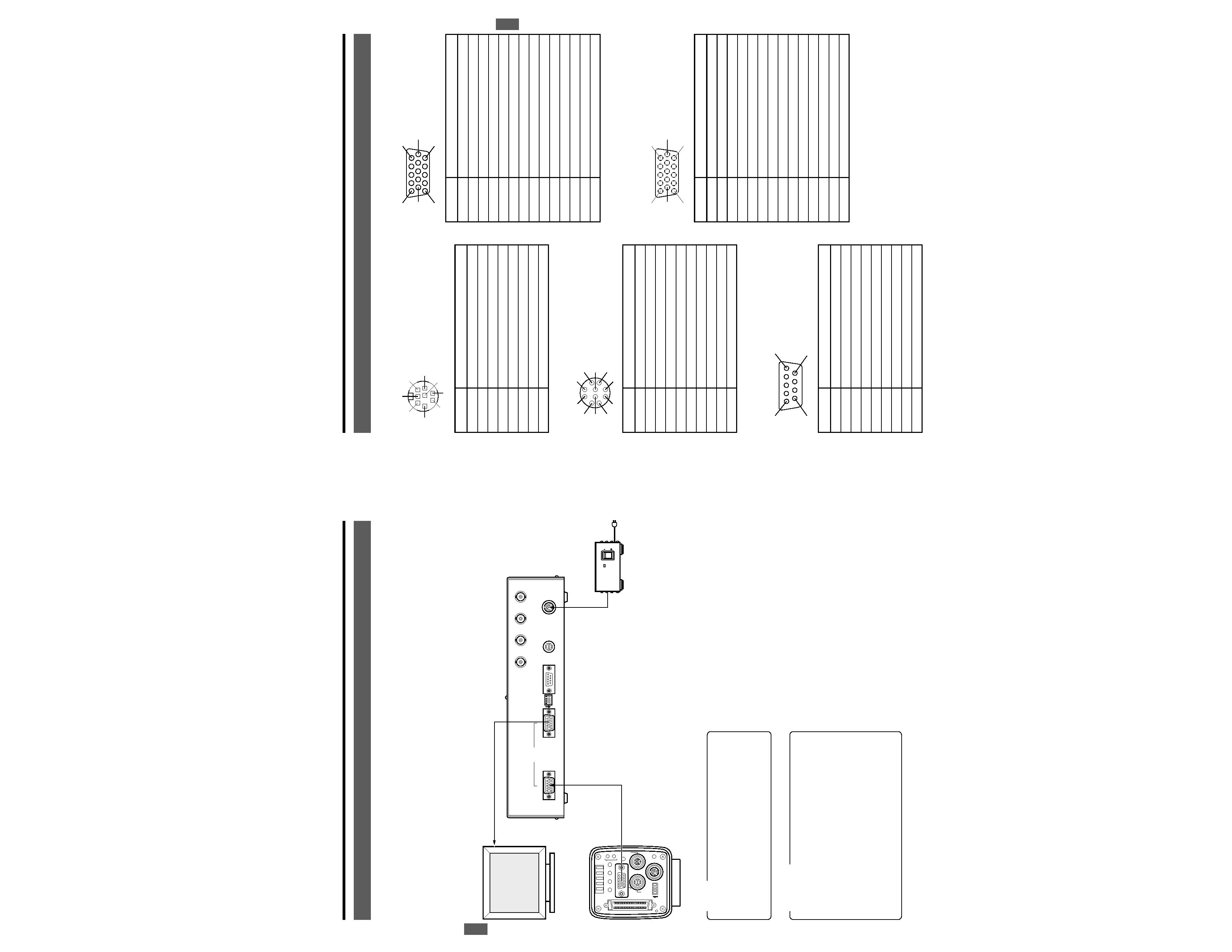
3-1 Pin Configuration
1 [DC 12V IN] Power Input Terminal
(Mini DIN 8-pin, female)
2 [CAMERA CTL] Camera Control Terminal
3 [RS-232C] Serial RemoteTerminal (D-Sub 9-pin, male)
5 [VIDEO OUTPUT] Terminal
(Mini D-Sub 15-pin female)
6 [VIDEO INPUT] Terminal
(Mini D-Sub 15-pin, female)
1
4
3
6
7
8
5
2
Pin No.
Signal Name
1NC
2
GND
3NC
4NC
5
GND
6
12V IN
7NC
8
12V IN
Pin No.
Signal Name
1
A.WHITE (Auto White Balance Control Output)
2
FREEZE (Freeze Control Output)
3
WEN (Write Enable Input)
4
FLASH (Flash Control Input)
5
SEND (SCSI Output Control Output)
6
RS-SDI (Serial Remote Camera Input)
7
RS-SDO (Serial Remote Camera Output)
8
GND
9
12 V Input
10
OPERATION (Remote Connection Control)
1
2
8
7
10
6
3
4
5
9
Pin No.
Signal Name
1NC
2
RXD
3
TXD
4
DTR
5
GND
6
DSR
7RTS
8
CTS
9NC
Pin No.
Signal Name
1
R OUT
2
G OUT
3
B OUT
4NC
5NC
6
R GND
7
G GND
8
B GND
9NC
10-11
GND
12
NC
13
HS OUT
14
VS OUT
15
NC
1
5
10
6
11
15
1
5
10
6
11
15
Pin No.
Signal Name
1R IN
2G IN
3B IN
4NC
5NC
6
R GND
7
G GND
8
B GND
9NC
10-11
GND
12
NC
13
HS IN
14
VS IN
15
NC
5
1
9
6