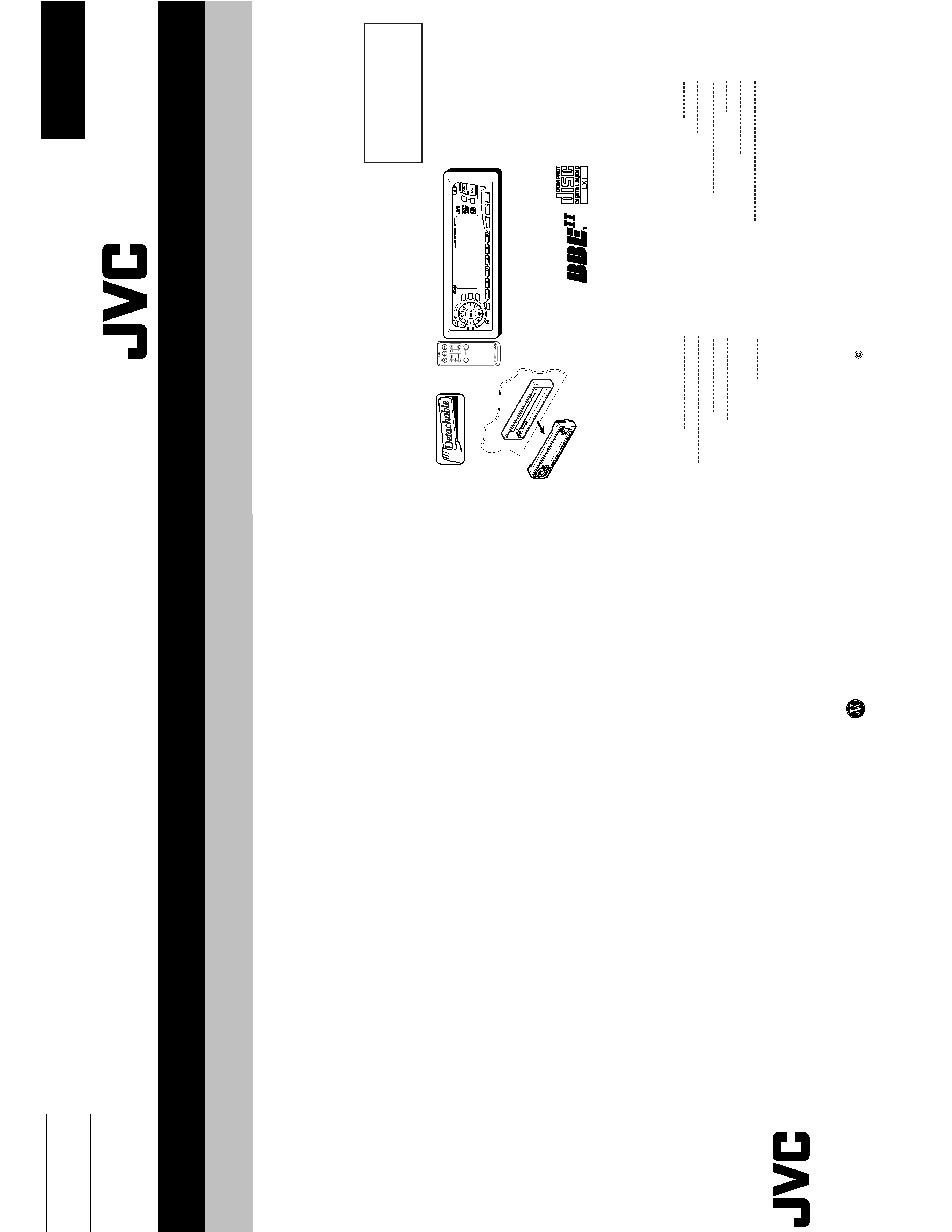
SERVICE MANUAL
CD RECEIVER
No.49539
Feb. 2000
COPYRIGHT
2000 VICTOR COMPANY OF JAPAN, LTD.
This service manual is made from 100% redycled paper.
Printed in Japan
200002(V)
VICTOR COMPANY OF JAPAN, LIMITED
MOBILE ELECTRONICS DIVISION,10-1,1Chome,Ohwatari-machi,maebashi-city,Japan
KD-SX950
(No.49539)
KD-SX950
KD-SX950
Area Suffix
J ---- Northerm America
Contents
Safety precaution
1-2
Instructions
1-3~16
Disassembly method
2-1
Adjustment method
2-6
Flow of functional operation
until TOC read
2-7
Maintenance of laser pickup
2-9
Description of major ICs
2-10
Block diagram
2-26
Standard schematic diagrams
2-27
Printed circuit boards
2-29~31
Parts list
3-1~
CD
DISP
SCM
RPT
SSM
BBE
MO
RND
789
CD CHANGER CONTROL
10
11
12
INT
CD-CH
FM/AM
/I ATT
/
SCAN
! CAUTION Burrs formed during molding may be left over on some parts of the chassis. Therefore,
pay attention to such burrs in the case of preforming repair of this system.
Safety precaution
! CAUTION Please use enough caution not to see the beam directly or touch it in case of an
adjustment or operation check.
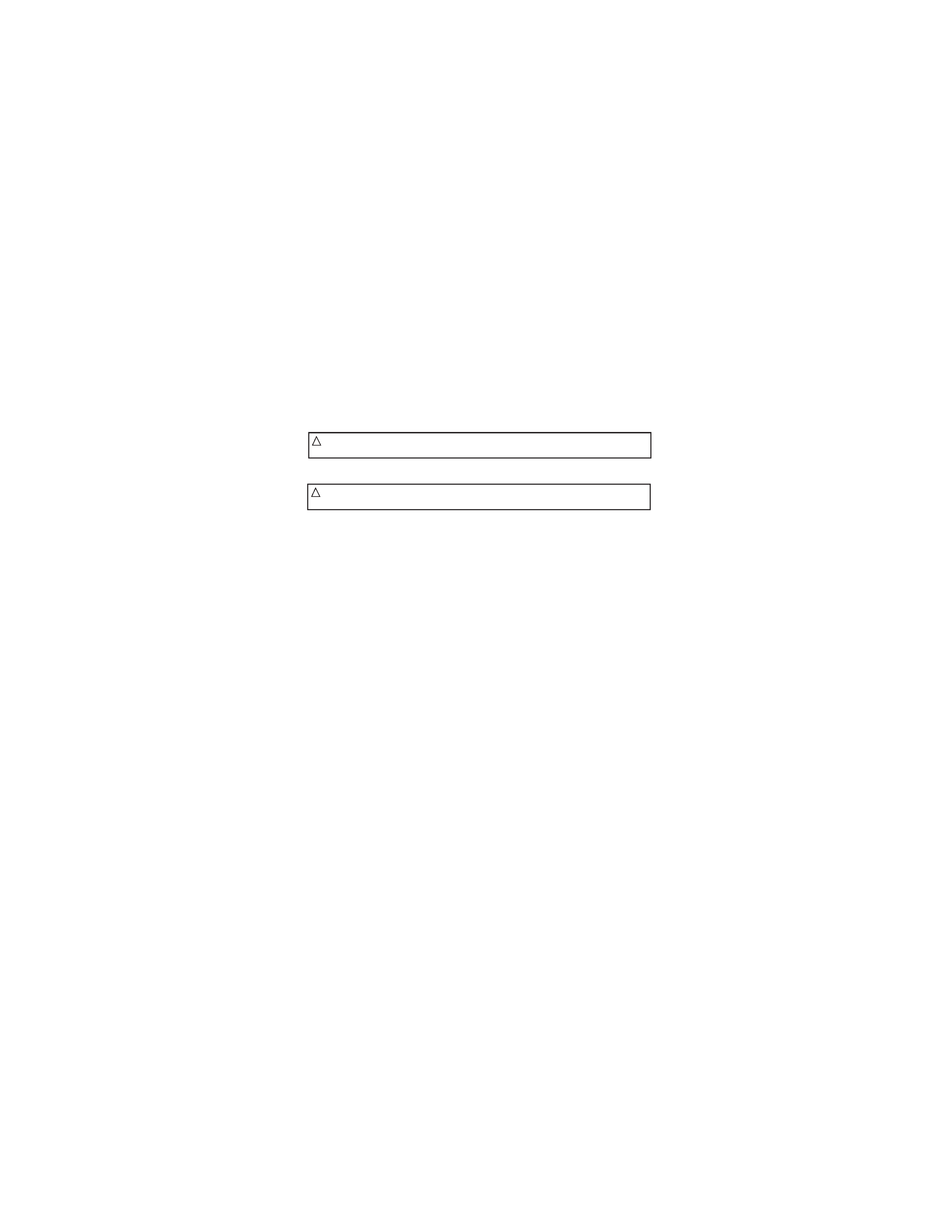
Disasembly method
Removing the front panel unit
1.Press the Eject button to open the front panel unit
(See fig 1)
2.Push and open the right and left open/close shaft arms
outward to remove the shaft.(See fig 2)
3.Remove the front panel unit from the same side as the
shaft was removed.
1.Remove the front panel unit.
2.Remove the two screwsA bsecuring the front chassis
assembly.(See fig 3)
3.Remove the four ribsa asecuring the front chassis
assembly to the chassis.(See fig 4)
Removing the front chassis assembly
Removing the bottom cover assembly
Turn the unit upside down,then insert and turn to
b the screwdriver to remove the bottom cover.
(See fig 5)
Fig 5
Fig 1
Eject button
Front panel unit
Fig 2
Open/close
shaft arm
Fig 3
A
a
Fig 4
a
b
b
b
b
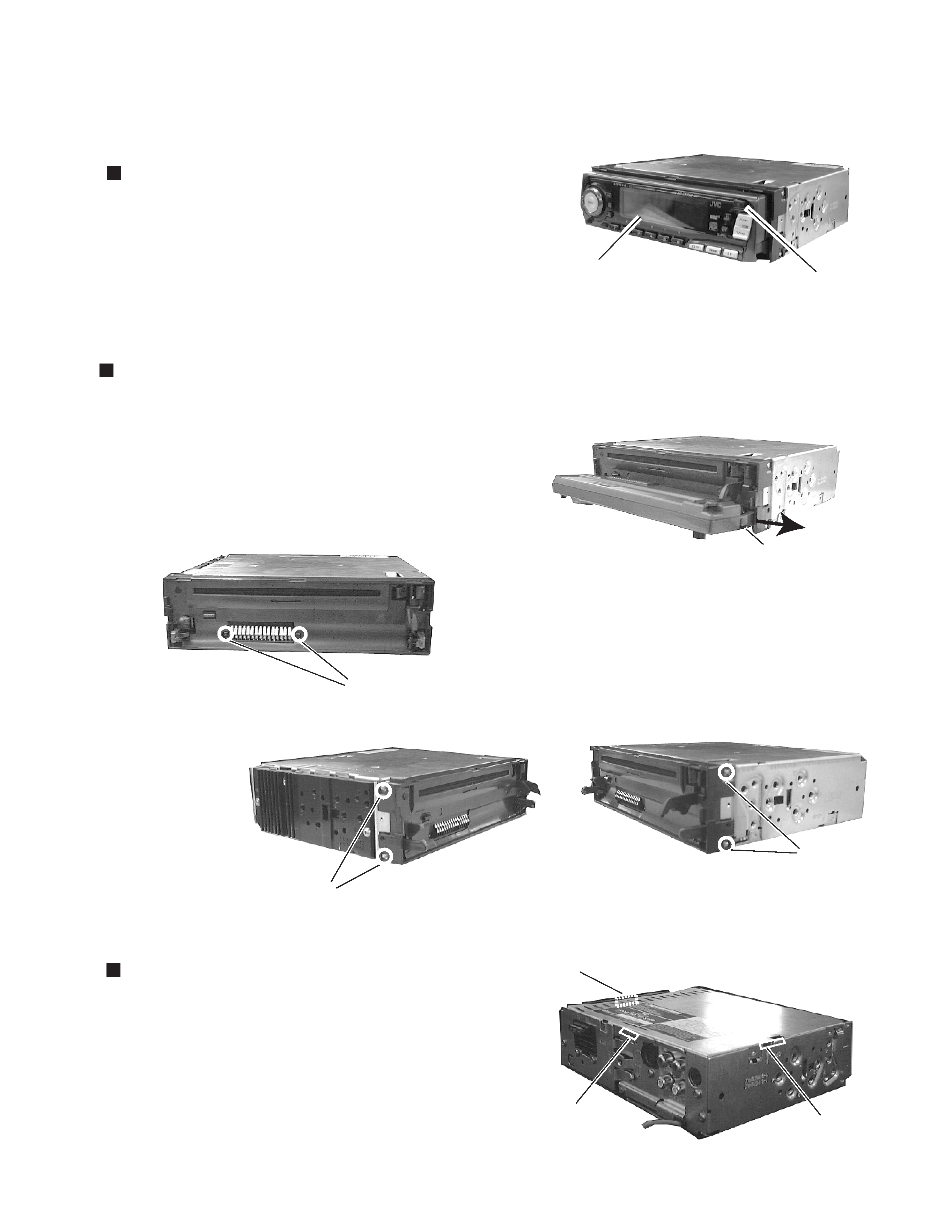
1.Remove three screws E retaining the rear panel to the
chassis
2.Remove one screw C retaining the IC to the heat sink.
3.Remove two screws D retaining the main bord.
4.Lift up the main board to remove it.
5.Remove two screws B to remove the heat sink.
Removing the rear brackt (See fig7)
1.Remove one screw I to remove the IC bracket.
2.Remove one screw F to remove the line-out jack.
3.Remove one screw G to remove the antenna jack.
4.Remove one screw H to remove the connector.
5.Remove one screw L to remove the connector.
CD mechanism assembly (See fig8)
Remove three mechanism mounting screws J retaining the
top cover.
Front panel unit (See fig9)
Remove five screws K retaining the rear cover.
Removing the main board(wiht rear panel)
(See fig6.7)
Fig 9
Fig 8
J
J
J
B
B
C
Fig 6
K
K
K
K K
E
G
Fig 7
E
E
I
L
L
H
F
D
D
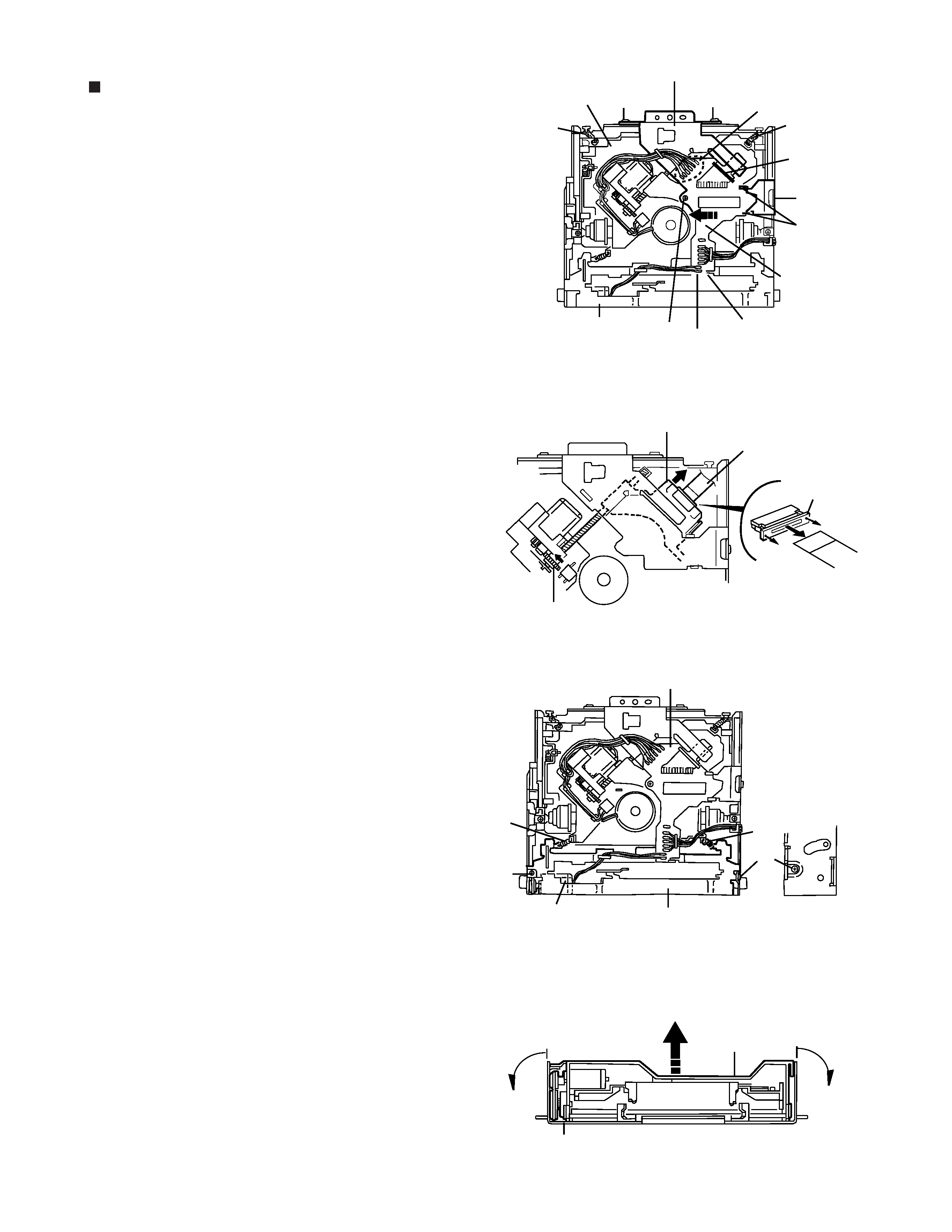
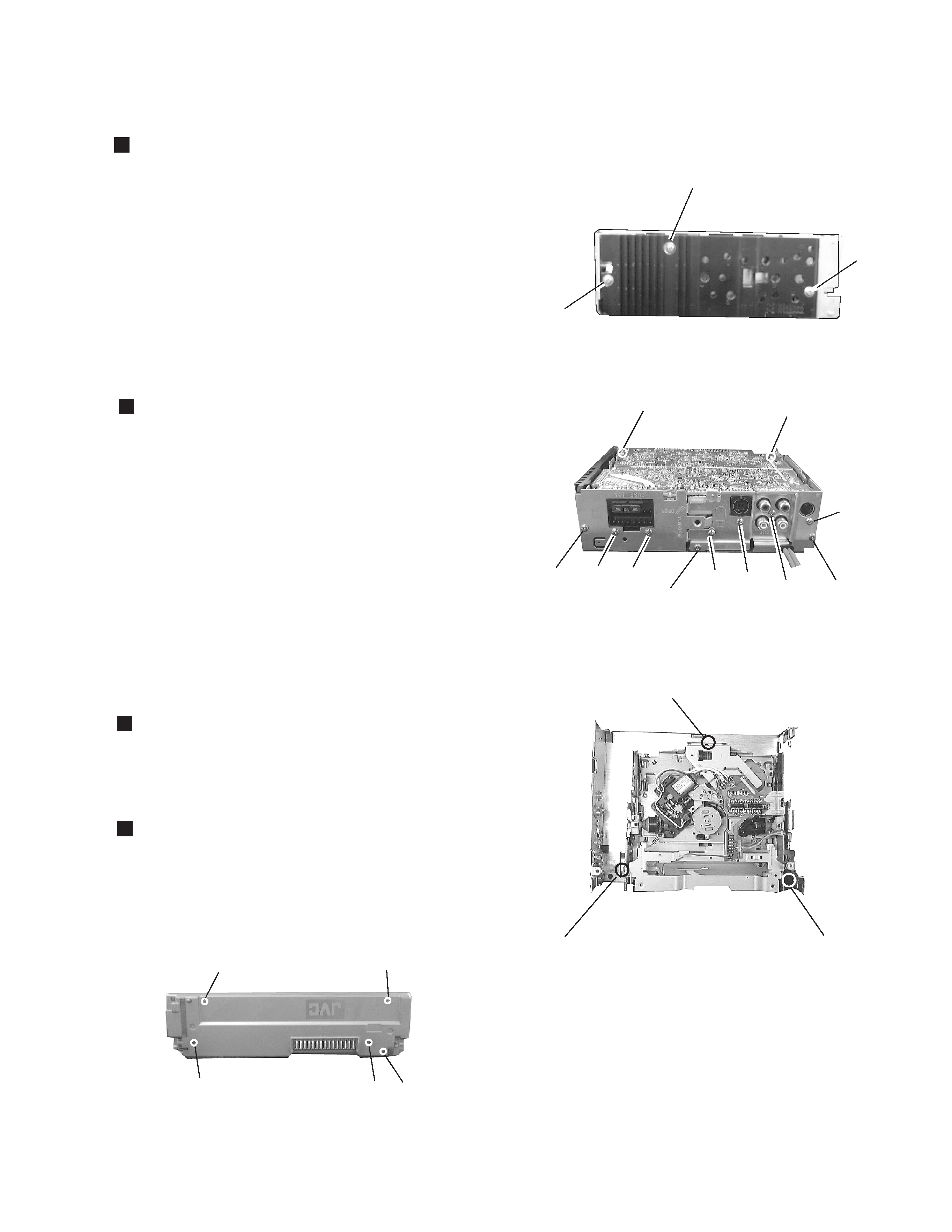
Unsolder the part f and g on the CD mechanism
control board.
Remove the stator fixing the CD mechanism control
board and the damper bracket (To remove the stator
smoothly, pick up the center part).
Remove the screw F attaching the CD mechanism
control board.
Remove the CD mechanism control board in the
direction of the arrow while releasing it from the two
damper bracket slots i and the front bracket slot j.
Disconnect the flexible wire from connector on the
pickup unit.
Removing the CD mechanism control
board(See Fig.1 and 2)
Turn the FD gear in the direction of the
arrow to move the entire pickup unit to
the appropriate position where the
flexible wire of the CD mechanism unit
can be disconnected easily (Refer to
Fig.2).
ATTENTION:
Fig.1
Fig.2
Fig.3
Fig.4
Front bracket
CD mechanism
control board
Shift the lock
Flexible wire
Pickup unit
FD gear
CD mechanism control board
Loading motor
Front bracket
Front bracket
Pull outward
Pull outward
Flame
Damper bracket
m
m
h
i
g
f
I
I
I
CD mechanism ass'y
F
j
k
G
k
G