SERVICE MANUAL
COPYRIGHT © 2003 VICTOR COMPANY OF JAPAN, LTD.
No.49793
2003/
5
CD RECEIVER
49793
2003
4
KD-LX555R
TABLE OF CONTENTS
1
Precautions . . . . . . . . . . . . . . . . . . . . . . . . . . . . . . . . . . . . . . . . . . . . . . . . . . . . . . . . . . . . . . . . . . . . . . . . . . . . 3
2
Disassembly method . . . . . . . . . . . . . . . . . . . . . . . . . . . . . . . . . . . . . . . . . . . . . . . . . . . . . . . . . . . . . . . . . . . . 5
3
Adjustment. . . . . . . . . . . . . . . . . . . . . . . . . . . . . . . . . . . . . . . . . . . . . . . . . . . . . . . . . . . . . . . . . . . . . . . . . . . . 28
4
Description of major ICs. . . . . . . . . . . . . . . . . . . . . . . . . . . . . . . . . . . . . . . . . . . . . . . . . . . . . . . . . . . . . . . . . 32
S
KD-LX555R
10
7
8
9
11
12
STD
M
SOURCE
Area Suffix
E ------ Continental Europe

1-2 (No.49793)
SPECIFICATION
Design and specifications are subject to change without notice.
AUDIO AMPLIFIER SECTION Maximum Power Output
Front
50 W per channel
Rear
50 W per channel
Continuous Power Output (RMS) Front
19 W per channel into 4
, 40 Hz to 20 000 Hz
at no more than 0.8% total harmonic distortion.
Rear
19 W per channel into 4
, 40 Hz to 20 000 Hz
at no more than 0.8% total harmonic distortion.
Load Impedance
4
(4 to 8 allowance)
Equalizer Control Range:
LOW
±12 dB (50 Hz, 80 Hz, 120 Hz)
MID
±12 dB (700 Hz, 1 kHz, 2 kHz)
HIGH
±12 dB (8 kHz, 12 kHz)
Frequency Response
40 Hz to 20 000 Hz
Signal-to-Noise Ratio
70 dB
Line-Out Level/Impedance
2.0 V/20 k
load (full scale)
Output Impedance
1 k
TUNER SECTION
Frequency Range
FM
87.5 MHz to 108.0 MHz
AM
(MW) 522 kHz to 1 620 kHz
(LW) 144 kHz to 279 kHz
[FM Tuner]
Usable Sensitivity
11.3 dBf (1.0
µV/75 )
50 dB Quieting Sensitivity
16.3 dBf (1.8
µV/75 )
Alternate Channel Selectivity (400 kHz)
65 dB
Frequency Response
40 Hz to 15 000 Hz
Stereo Separation
30 dB
Capture Ratio
1.5 dB
[MW Tuner]
Sensitivity
20
µV
Selectivity
35 dB
[LW Tuner]
Sensitivity
50
µV
CD PLAYER SECTION
Type
Compact disc player
Signal Detection System
Non-contact optical pickup (semiconductor laser)
Number of channels
2 channels (stereo)
Frequency Response
5 Hz to 20 000 Hz
Dynamic Range
98 dB
Signal-to-Noise Ratio
102 dB
Wow and Flutter
Less than measurable limit
MP3 decoding format
MPEG1/2 Audio Layer 3
Max. Bit Rate:320 Kbps
GENERAL
Power Requirement:
Operating Voltage DC 14.4 V (11 V to 16 V allowance)
Grounding System
Negative ground
Allowable Operating Temperature
0
°C to +40°C
Dimensions (W
× H × D)
Installation Size
182 mm
× 52 mm × 160 mm
Panel Size
188 mm
× 58 mm × 8 mm
Mass
1.8 kg (excluding accessories)
(No.49793)1-3
SECTION 1
Precautions
1.1
Safety Precautions
!
Burrs formed during molding may be left over on some parts of the chassis. Therefore,
pay attention to such burrs in the case of preforming repair of this system.
!
Please use enough caution not to see the beam directly or touch it in case of an
adjustment or operation check.
1-4 (No.49793)
1.2
Preventing static electricity
Electrostatic discharge (ESD), which occurs when static electricity stored in the body, fabric, etc. is discharged, can destroy the laser
diode in the traverse unit (optical pickup). Take care to prevent this when performing repairs.
1.2.1
Grounding to prevent damage by static electricity
Static electricity in the work area can destroy the optical pickup (laser diode) in devices such as CD players.
Be careful to use proper grounding in the area where repairs are being performed.
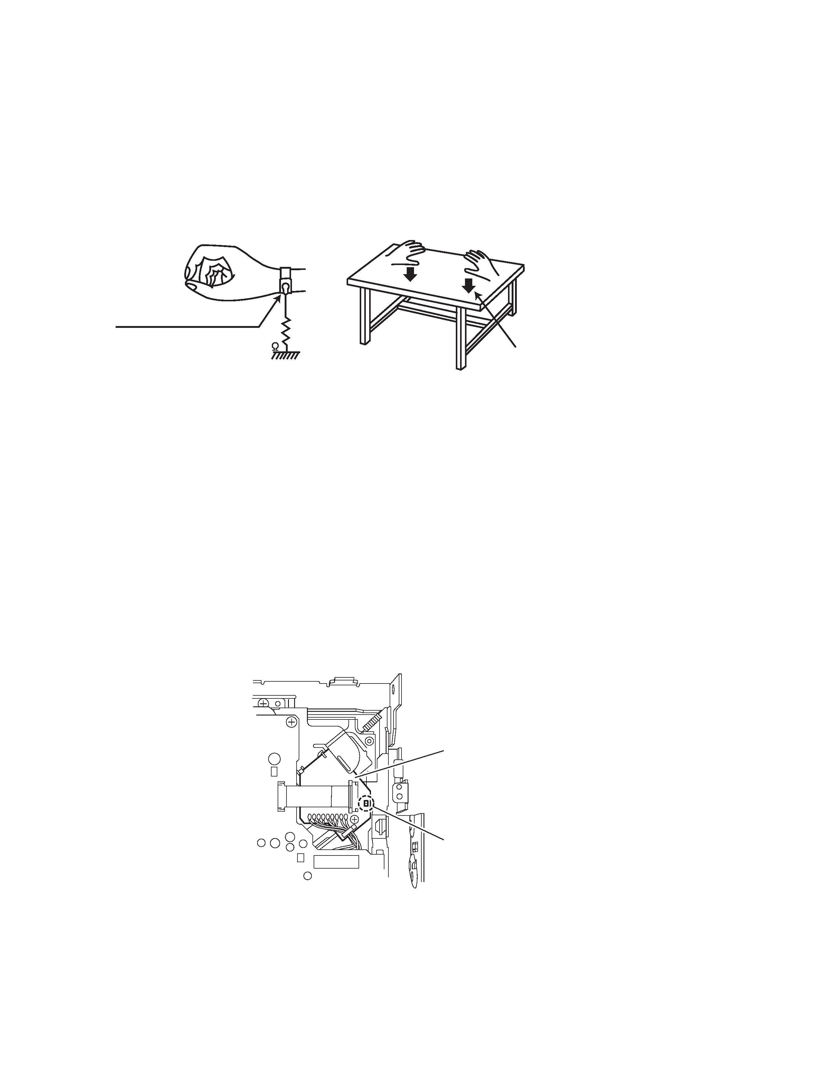
(1) Ground the workbench
Ground the workbench by laying conductive material (such as a conductive sheet) or an iron plate over it before placing the
traverse unit (optical pickup) on it.
(2) Ground yourself
Use an anti-static wrist strap to release any static electricity built up in your body.
(3) Handling the optical pickup
· In order to maintain quality during transport and before installation, both sides of the laser diode on the replacement optical
pickup are shorted. After replacement, return the shorted parts to their original condition.
(Refer to the text.)
· Do not use a tester to check the condition of the laser diode in the optical pickup. The tester's internal power source can easily
destroy the laser diode.
1.3
Handling the traverse unit (optical pickup)
(1) Do not subject the traverse unit (optical pickup) to strong shocks, as it is a sensitive, complex unit.
(2) Cut off the shorted part of the flexible cable using nippers, etc. after replacing the optical pickup. For specific details, refer to the
replacement procedure in the text. Remove the anti-static pin when replacing the traverse unit. Be careful not to take too long a
time when attaching it to the connector.
(3) Handle the flexible cable carefully as it may break when subjected to strong force.
(4) It is not possible to adjust the semi-fixed resistor that adjusts the laser power. Do not turn it.
1.4
Attention when traverse unit is decomposed
*Please refer to "Disassembly method" in the text for the CD pickup unit.
· Apply solder to the short land before the flexible wire is disconnected from the connector on the CD pickup unit.
(If the flexible wire is disconnected without applying solder, the CDpickup may be destroyed by static electricity.)
· In the assembly, be sure to remove solder from the short land after connecting the flexible wire.
1M
(caption)
Anti-static wrist strap
Conductive material
(conductive sheet) or iron plate
Connector board
Soldering
(No.49793)1-5
SECTION 2
Disassembly method
2.1
Main body
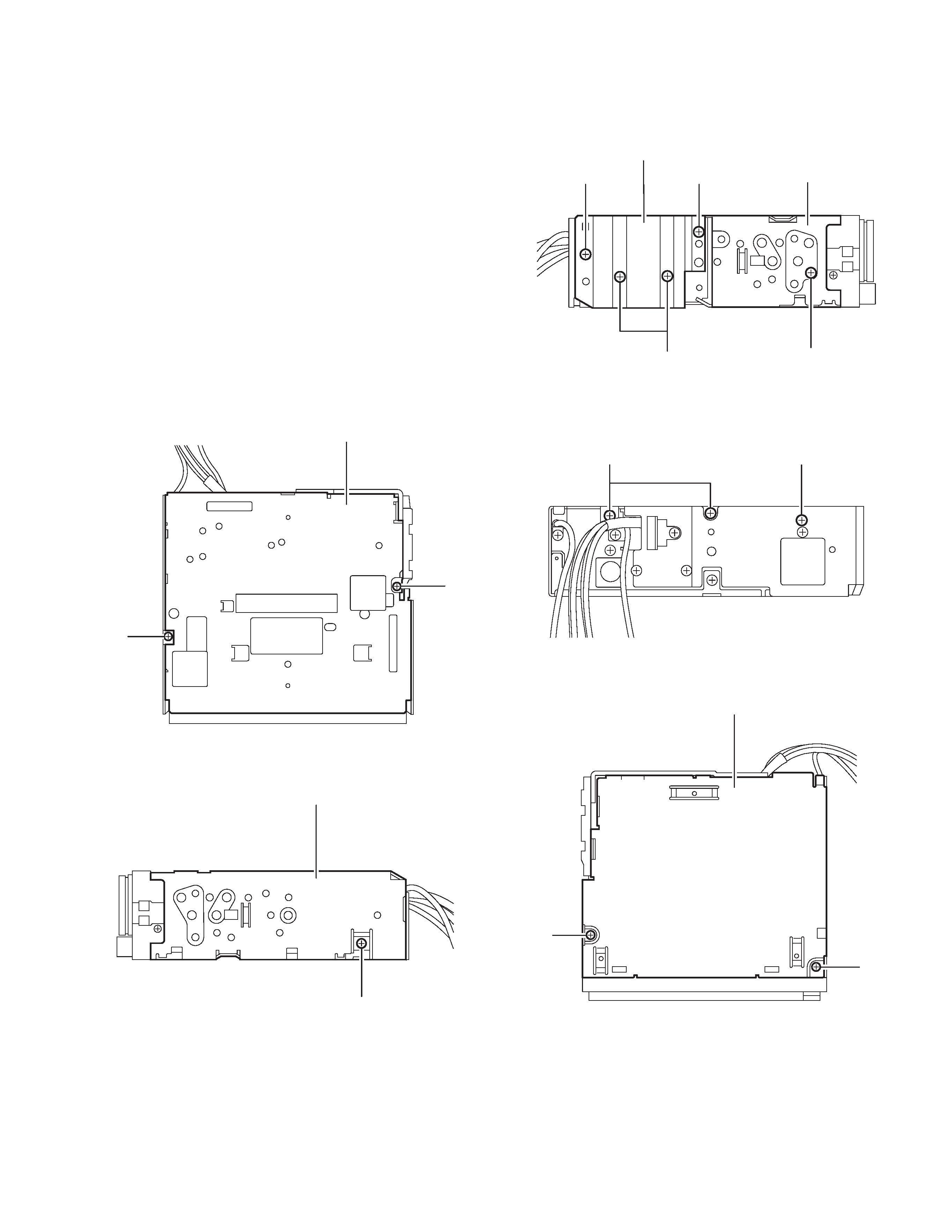
2.1.1 Removing the top chassis
(See Fig.1~5)
(1) Remove the two screws A attaching the bottom cover to
the top chassis on the bottom of the body.
(2) Remove the two screws B attaching the top chassis on
both sides of the body.
(3) Remove the screw C and the thee screws D attaching the
heat sink on the left side of the body.
(4) Remove the two screws E and the screw F on the back of
the body.
(5) Remove the two screws G on the upper side of the body.
(6) Move the top chassis upward and disconnect the CD
mechanism connector from the main board connector by
pulling it. Remove the top chassis from the body.
Fig.1
Fig.2
Fig.3
Fig.4
Fig.5
A
A
Bottom cover
B
Top chassis
C
D
B
D
Heat sink
Top chassis
E
F
G
G
Top chassis