COPYRIGHT © 2002 VICTOR COMPANY OF JAPAN, LTD
This service manual is printed on 100% recycled paper.
SERVICE MANUAL
Regarding service information other than these sections, refer to the service manual No. 82927 (HR-XV1EU-C).
Also, be sure to note important safety precautions provided in the service manual.
GENERAL
Fonctionne sur courant:
AC 230V 50Hz
Consommation électrique:
marche: 22W
veille: 5W
Poids:
4.5 kg
Dimensions:
largeur: 430 mm
Hauteur: 99 mm
profondeur: 310.5 mm
Niveau d'entrée:
Prise SCART: VIDEO: 1 Vp-p, 75
AUDIO: 500 mV, 50 k
Audio IN jack: 500 mV, 50 k
Niveau de sortie:
Prise SCART: VIDEO: 1 Vp-p, 75
AUDIO: 500 mV, 1 k
Audio OUT jack: 500 mV, 1 k
Hi-Fi Distorsion de fréquence: 20Hz to 20,000Hz
Hi-Fi Gamme d'amplification: More than 75dB
Magnétoscope
Signal couleur:
PAL et SECAM Lecture NTSC
Tête vidéo:
4 têtes rotatives
Piste audio:
Son Hi-Fi - 2 pistes/son mono - 1 piste
Couverture des canaux:
2-12, X, Y, Z, S1-S41, 21-69
Durée rembobinage rapide:
Environ 1 minute 48 secondes
(avec une cassette E-180) (à + 25°C)
Lecteur DVD
Système de signal:
PAL
Disque compatibles:
DVD (12cm, 8cm), CD (12cm, 8cm)
Caractéristiques audio:
DVD: 4Hz - 22KHz
Distorsion de fréquence:
CD: 4Hz - 20KHz
Taurapport signal/bruit
90dB
Distorsion harmonique:
0.1%
scintillement et pleurage:
En dessous des seuils de mesure
Gamme d'amplification:
90dB
sortie:
Audio: (RCA) 500 mV, 1Kohm
Digital Audio: 0.5Vp-p/75 ohm
Micro:
CD: longueur d'onde: 775 - 805 nm
Sortie maximum: 0.5 mW
DVD: longueur d'ondes: 640 - 660 nm
Sortie maximum: 1.0 mW
ACCESSOIRES:
Télécommande x 1
Câble coaxial 75 ohm x 1
Câble Scart x 1
Pile (UM-3) x 2
No.82943
August 2002
HR-XV1MS
HR-XV1MS V14PV1
LECTEUR DVD Hi-Fi VIDÉO MAGNÉTOSCOPE
Caractéristiques techniques
DIGITAL VIDEO
PAL SECAM

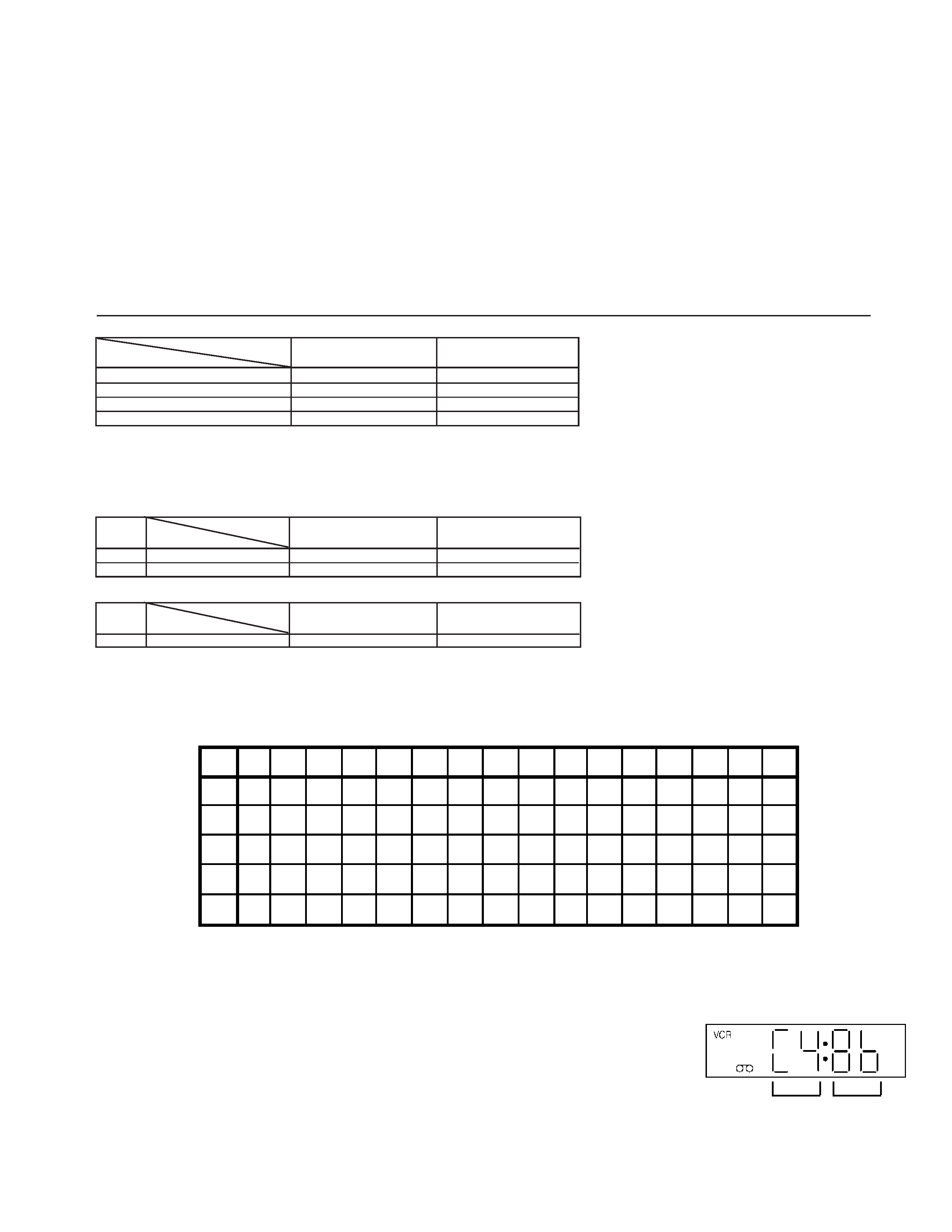
TABLE OF CONTENTS
The following table indicates main different points between models HR-XV1EU-C and HR-XV1MS.
MODEL
HR-XV1EU-C
ITEM
VIDEO SYSTEM
PAL
PAL/SECAM/MESECAM
RF OUT
USED
NOT USED
VPS
USED
NOT USED
21 PIN CABLE
OPTIONAL
PROVIDED
HR-XV1MS
DIFFERENT TABLE .............................................................................................................................................................................................. 1 only
WHEN REPLACING EEPROM(MEMORY) IC ........................................................................................................................................... 1 only
2. CHARTS AND DIAGRAMS (2-1 to 2-13)
Y/C/AUDIO/H.AMP SCHEMATIC DIAGRAM ......................................................................................................................................... 2-1
MICOM SCHEMATIC DIAGRAM ........................................................................................................................................................... 2-3
TUNER/JACK SCHEMATIC DIAGRAM ................................................................................................................................................. 2-5
SUB MICOM/OSD/VPS SCHEMATIC DIAGRAM .................................................................................................................................. 2-7
PRINTED CIRCUIT BOARD VCR ......................................................................................................................................................... 2-9
3. PARTS LIST (3-1 to 3-7)
3.1
PACKING AND ACCESSORY ASSEMBLY <M1> ................................................................................................................................. 3-1
3.2
ELECTRICAL PART LIST
VCR BOARD ASSEMBLY<03> ................................................................................................................................................................ 3-2
4. REFERENCE (4-1 to 4-6)
GENERAL SPECIFICATIONS ............................................................................................................................................................... 4-1
The following table indicates different parts number between models HR-XV1EU-C and HR-XV1MS.
PACKING AND ACCESSORY ASSEMBLY<M1>
PACKING AND ACCESSORY ASSEMBLY<M1> is indicated on the parts list.
VCR BOARD ASSEMBLY<03>
REF
NO.
!
MODEL
ITEM
PW1
VCR BOARD ASSY
X-A2A735B010
X-A2A779D010B
HR-XV1EU-C
HR-XV1MS
1
REF
NO.
!
MODEL
ITEM
!601
CABINET,FRONT ASSY
X-A2A735B720
X-A2A779D720
608
CABINET,FRONT
X-701WPJB706
X-701WPJ1135
HR-XV1EU-C
HR-XV1MS
WHEN REPLACING EEPROM (MEMORY) IC
If a service repair is undertaken where it has been required to change the MEMORY IC, the following steps should be taken to
ensure correct data settings while making reference to TABLE 1.
NOTE: No need setting for after INI FD.
[TABLE 1]
1.
2.
3.
4.
5.
6.
7.
8.
The unit will now have the correct DATA for the new MEMORY IC.
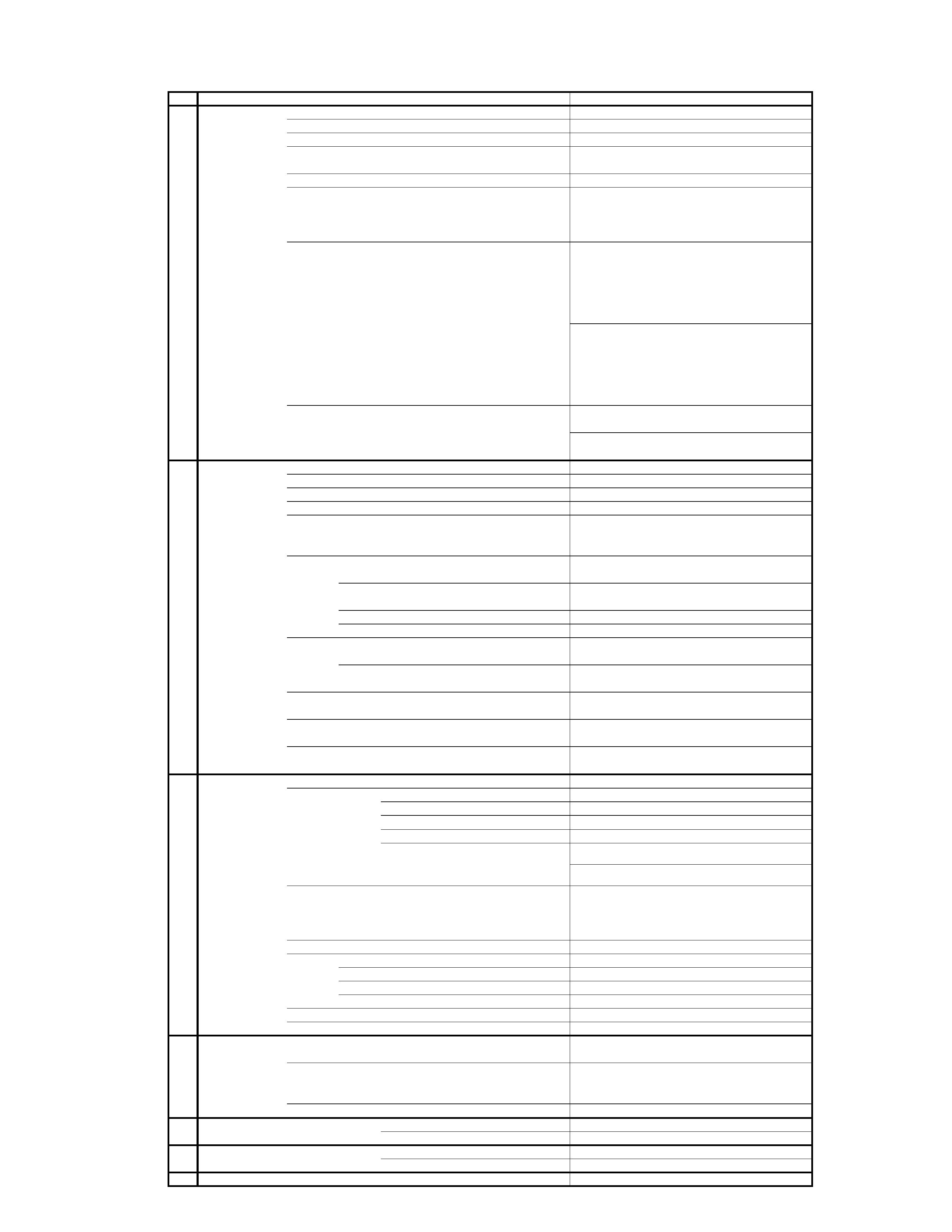
Turn on the POWER.
Press both CH UP button on the set and the FF button on the set for more than 2 seconds.
ADDRESS and DATA will appear on FIP as Fig 1.
ADDRESS is now selected and should "blink". Using the SET + or - button on the remote,
step through the ADDRESS until required ADDRESS to be changed is reached.
Press OK to select DATA. When DATA is selected, it will "blink".
Again, step through the DATA using SET + or - button until required DATA value has been
selected.
Pressing OK will take you back to ADDRESS for further selection if necessary.
Repeat steps 3 to 6 until all data has been checked.
When satisfied correct DATA has been entered, turn POWER off (return to STANDBY
MODE) to finish DATA input.
Fig. 1
ADDRESS
DATA
INI
+0
+1
+2
+3
+4
+5
+6
+7
+8
+9
+A
+B
+C
+D
+E
+F
B0
---
---
---
---
---
---
---
---
---
8B
C9
D2
71
62
76
08
C0
B2
17
90
50
60
F1
54
51
51
51
B2
9F
97
8E
04
FA
D0
D9
64
2A
08
02
FF
40
00
71
9F
82
02
42
35
63
5B
E0
76
5F
08
F0
0A
FB
5F
08
F0
05
F2
5F
09
F0
05
F3
F0
16
2F
9F
42
42
80
3D
68
08
89
04
3A
CC
---
---
---
FINAL ASSEMBLY<M2>

4-1
GENERAL SPECIFICATIONS
<Reference>
G-1
Outline of the product
DVD VIDEO PLAYER & VHS Player / Recorder
G-2
DVD System
Color System
PAL
Disc
DVD, CD-DA, CD-R/RW, VIDEO CD
Disc Diameter
120 mm , 80 mm
Deck
Disc Loading System
Front Disc Loading
Motor
3 Motors
Pick up
1-Lens 2-Beams System
Playback time (Max)
DVD 1-Layer
135min
(4.7GB)
DVD 2-Layer
245min
(8.5GB)
CD
74min
VIDEO CD
74min
Search speed
Fwd
2-100 times / 4 step (DVD)
4-8 times / 2 step (CD)
5-15 times / 2 step (VIDEO CD)
Actual
2-70 times (DVD)
4-12times (CD)
4-18times (VIDEO CD)
Rev
2-100 times / 4 step (DVD)
4-8 times / 2 step (CD)
5-15 times / 2 step (VIDEO CD)
Actual
2-70 times (DVD)
4-12times (CD)
4-18times (VIDEO CD)
Slow speed
Fwd
1/8-1/2 times (DVD, VIDEO CD)
Actual
1/7-1/2 times (DVD, VIDEO CD)
Rev
--
Actual
--
G-3
VCR
System
VHS Player / Recorder
System
Video System
PAL/SECAM/MESECAM
Hi-Fi STEREO
Yes
NTSC PB(PAL60Hz)
Yes
Deck
DECK
OVD-7
Loading System
Front
Motor
3
Heads
Video Head
4Head
FM Audio Head
2Head
Audio /Control
Mono/Yes
Erase(Full Track Erase)
Yes
Tape
Rec
PAL
SP/LP
Speed
NTSC
-
Play
PAL
SP/LP
NTSC
SP
Fast Forward / Rewind Time (Approx.) at 25
oC
FF:1'48"/REW:1'48"
with Cassette
E-180
Forward/Reverse
NTSC or PAL-M
SP=3x, 5x
Picture Search
PAL or SECAM
SP/LP=5x, 7x / 7x, 13x
Frame Advance
1/10
Slow Speed
1/5, 1/10,1/30
G-4
Tuning
Broadcasting System
CCIR,FRENCH
System BG,L
System
Tuner and
System
1Tuner
Receive CH
Destination
Oscar(W/HYPER ) , France CATV
Tuning System
F-Synth
Input Impedance
VHF/UHF
75 OHM
CH Coverage
(SECAM)
(PAL)
Intermediate
Picture(FP)
38.9 / 38.9 / 34.4MHz
Frequency
Sound(FS)
33.4 / 32.4 / 40.9MHz
FP-FS
5.5 / 6.5 / 6.5MHz
Preset CH
80CH
RF Converter Output
No
Channel
-
Level/Impedance
-
Sound Selector
No
Stereo/Dual TV Sound
G.ST/NICAM DUAL
Tuner Sound Muting
Yes
G-5
Power
Power Source
AC
230V
50Hz
DC
-
Power Consumption
22 W at 230V 50Hz
Stand by
5 W at 230V 50Hz
Per Year
-- W
Protector
Power Fuse
Yes
G-6
Regulation
Safety
CE
Radiation
CE
G-7
Temperature
Operation
5
oC - 40oC
Storage
-20
oC - 60oC
G-8
Operating Humidity
Less then 80% RH
PAL/SECAM(U&VH)/SECAM(VL)
F2~F4, FB~FQ, F21~F69
E2~E4, X~Z+2, S1~S10, E5~E12,S11~S41,E21~E69