SERVICE MANUAL
COPYRIGHT © 2003 VICTOR COMPANY OF JAPAN, LTD.
No.82961
2003/4
VIDEO CASSETTE RECORDER
82961
2003
4
HR-S5960EX,HR-S5961EX,
HR-S5962EX,HR-S5963EX,
HR-S5965EF,HR-S5965EK,
HR-S5966EK
SPECIFICATION (The specifications shown pertain specifically to the model HR-S5960EX,S5961EX,S5962EX,S5963EX)
GENERAL
VIDEO/AUDIO
TUNER/TIMER
ACCESSORIES
For disassembling and assembling of MECHANISM ASSEMBLY, refer to the SERVICE MANUAL No.86700 (MECHANISM ASSEMBLY).
(EK model)
(other model)
Power requirement
AC 220 V - 240 V~, 50 Hz/60 Hz
Power consumption
Power on
16 W
Power off
3.5 W
Temperature
Operating
5°C to 40°C
Storage
-20°C to 60°C
Operating position
Horizontal only
Dimensions
(W x H x D)
400 mm x 94 mm x 270 mm
Weight
3.1 kg
Format
S-VHS/VHS PAL standard
Maximum recording time
(SP)
240 min. with E-240 video cassette
(LP)
480 min. with E-240 video cassette
Signal system
PAL-type colour signal and CCIR
monochrome signal, 625 lines 50 fields
Recording system
DA4 (Double Azimuth) head helical scan
system
Signal-to-noise ratio
45 dB
Horizontal resolution
VHS
250 lines
S-VHS
400 lines
Frequency range
Normal audio
70 Hz to 10,000 Hz
Hi-Fi audio
20 Hz to 20,000 Hz
Input/Output
21-pin SCART connectors:
IN/OUT x 1, IN/DECODER x 1RCA con-
nectors:AUDIO OUT x 1
TV channel storage
capacity
99 positions (+AUX position)
Tuning system
Frequency synthesized tuner
Channel coverage
VHF
47 MHz - 89 MHz/104 MHz - 300 MHz/302
MHz - 470 MHz
UHF
470 MHz - 862 MHz
Aerial output
UHF channels 22 - 69 (Adjustable)
Memory backup time
Approx. 10 min.
Provided accessories
: RF cable, Infrared remote control unit,
Lithium battery - CR2032-
HR-S5960EX,HR-S5961EX,HR-S5962EX,HR-S5963EX,HR-S5965EF,HR-S5965EK,HR-S5966EK V16S0
1-2 (No.82961)
TABLE OF CONTENTS
1
PRECAUTIONS . . . . . . . . . . . . . . . . . . . . . . . . . . . . . . . . . . . . . . . . . . . . . . . . . . . . . . . . . . . . . . . . . . . . . . . . . . . .
1-3
1.1
SAFTY PRECAUTIONS . . . . . . . . . . . . . . . . . . . . . . . . . . . . . . . . . . . . . . . . . . . . . . . . . . . . . . . . . . . . . . . .
1-3
2
SPECIFIC SERVICE INSTRUCTIONS . . . . . . . . . . . . . . . . . . . . . . . . . . . . . . . . . . . . . . . . . . . . . . . . . . . . . . . . . . .
1-5
2.1
Manually removing the cassette tape . . . . . . . . . . . . . . . . . . . . . . . . . . . . . . . . . . . . . . . . . . . . . . . . . . . . . .
1-5
2.2
Removing the major parts . . . . . . . . . . . . . . . . . . . . . . . . . . . . . . . . . . . . . . . . . . . . . . . . . . . . . . . . . . . . . . .
1-6
2.3
Emergency display function. . . . . . . . . . . . . . . . . . . . . . . . . . . . . . . . . . . . . . . . . . . . . . . . . . . . . . . . . . . . . .
1-8
2.4
Service position . . . . . . . . . . . . . . . . . . . . . . . . . . . . . . . . . . . . . . . . . . . . . . . . . . . . . . . . . . . . . . . . . . . . .
1-13
2.5
Jig RCU mode . . . . . . . . . . . . . . . . . . . . . . . . . . . . . . . . . . . . . . . . . . . . . . . . . . . . . . . . . . . . . . . . . . . . . .
1-13
2.6
Mechanism service mode . . . . . . . . . . . . . . . . . . . . . . . . . . . . . . . . . . . . . . . . . . . . . . . . . . . . . . . . . . . . . .
1-14
2.7
Maintenance and inspection . . . . . . . . . . . . . . . . . . . . . . . . . . . . . . . . . . . . . . . . . . . . . . . . . . . . . . . . . . . .
1-14
3
ADJUSTMENT . . . . . . . . . . . . . . . . . . . . . . . . . . . . . . . . . . . . . . . . . . . . . . . . . . . . . . . . . . . . . . . . . . . . . . . . . . . .
1-15
3.1
Before adjustment . . . . . . . . . . . . . . . . . . . . . . . . . . . . . . . . . . . . . . . . . . . . . . . . . . . . . . . . . . . . . . . . . . . .
1-15
3.2
Mechanism compatibility adjustment. . . . . . . . . . . . . . . . . . . . . . . . . . . . . . . . . . . . . . . . . . . . . . . . . . . . . .
1-16
3.3
Electrical adjustment . . . . . . . . . . . . . . . . . . . . . . . . . . . . . . . . . . . . . . . . . . . . . . . . . . . . . . . . . . . . . . . . . .
1-18
CHARTS AND DIAGRAMS
BOARD INTERCONNECTIONS . . . . . . . . . . . . . . . . . . . . . . . . . . . . . . . . . . . . . . . . . . . . . . . . . . . . . . . . . . 2-3
MAIN (VIDEO/N.AUDIO) SCHEMATIC DIAGRAM . . . . . . . . . . . . . . . . . . . . . . . . . . . . . . . . . . . . . . . . . . . . 2-5
MAIN (S-SUB) SCHEMATIC DIAGRAM . . . . . . . . . . . . . . . . . . . . . . . . . . . . . . . . . . . . . . . . . . . . . . . . . . . . 2-7
MAIN (SYSCON) SCHEMATIC DIAGRAM . . . . . . . . . . . . . . . . . . . . . . . . . . . . . . . . . . . . . . . . . . . . . . . . . . 2-9
DIFFERENCE TABLE OF SYSTEM CONTROL CIRCUIT . . . . . . . . . . . . . . . . . . . . . . . . . . . . . . . . . . . . . 2-11
REMOTE CONTROLLER SCHEMATIC DIAGRAM . . . . . . . . . . . . . . . . . . . . . . . . . . . . . . . . . . . . . . . . . . 2-11
FDP GRID ASSIGNMENT AND ANODE CONNECTION . . . . . . . . . . . . . . . . . . . . . . . . . . . . . . . . . . . . . . 2-11
MAIN (VPS/PDC SLICER) SCHEMATIC DIAGRAM . . . . . . . . . . . . . . . . . . . . . . . . . . . . . . . . . . . . . . . . . 2-12
MAIN (FMA) SCHEMATIC DIAGRAM. . . . . . . . . . . . . . . . . . . . . . . . . . . . . . . . . . . . . . . . . . . . . . . . . . . . . 2-13
MAIN (SW.REG) SCHEMATIC DIAGRAM . . . . . . . . . . . . . . . . . . . . . . . . . . . . . . . . . . . . . . . . . . . . . . . . . 2-15
MAIN (TUNER) SCHEMATIC DIAGRAM . . . . . . . . . . . . . . . . . . . . . . . . . . . . . . . . . . . . . . . . . . . . . . . . . . 2-17
MAIN (FRONT), LED AND ADV.JOG SCHEMATIC DIAGRAMS . . . . . . . . . . . . . . . . . . . . . . . . . . . . . . . . 2-19
MAIN (TERMINAL) SCHEMATIC DIAGRAM . . . . . . . . . . . . . . . . . . . . . . . . . . . . . . . . . . . . . . . . . . . . . . . 2-21
S-P CONVERTER SCHEMATIC DIAGRAM [HR-S5965EF]. . . . . . . . . . . . . . . . . . . . . . . . . . . . . . . . . . . . 2-23
SECAM SCHEMATIC DIAGRAM [HR-S5965EF] . . . . . . . . . . . . . . . . . . . . . . . . . . . . . . . . . . . . . . . . . . . . 2-25
COMPONENT PARTS LOCATION GUIDE <MAIN> LPB10189-001C. . . . . . . . . . . . . . . . . . . . . . . . . . . . 2-26
MAIN CIRCUIT BOARD . . . . . . . . . . . . . . . . . . . . . . . . . . . . . . . . . . . . . . . . . . . . . . . . . . . . . . . . . . . . . . . 2-27
S-P COVERTER AND SECAM CIRCUIT BOARDS [HR-S5965EF] . . . . . . . . . . . . . . . . . . . . . . . . . . . . . . 2-29
CPU PIN FUNCTION . . . . . . . . . . . . . . . . . . . . . . . . . . . . . . . . . . . . . . . . . . . . . . . . . . . . . . . . . . . . . . . . . 2-30
SYSTEM CONTROL BLOCK DIAGRAM . . . . . . . . . . . . . . . . . . . . . . . . . . . . . . . . . . . . . . . . . . . . . . . . . . 2-31
AUDIO BLOCK DIAGRAM . . . . . . . . . . . . . . . . . . . . . . . . . . . . . . . . . . . . . . . . . . . . . . . . . . . . . . . . . . . . . 2-32
VIDEO BLOCK DIAGRAM (1) . . . . . . . . . . . . . . . . . . . . . . . . . . . . . . . . . . . . . . . . . . . . . . . . . . . . . . . . . . . 2-33
VIDEO BLOCK DIAGRAM (2) . . . . . . . . . . . . . . . . . . . . . . . . . . . . . . . . . . . . . . . . . . . . . . . . . . . . . . . . . . . 2-35
VOLTAGE CHARTS . . . . . . . . . . . . . . . . . . . . . . . . . . . . . . . . . . . . . . . . . . . . . . . . . . . . . . . . . . . . . . . . . . 2-37
PARTS LIST
1.
EXPLODED VIEW
1.1
PACKING AND ACCESSORY ASSEMBLY <M1> . . . . . . . . . . . . . . . . . . . . . . . . . . . . . . . . . . . . . . . . 3-1
1.2
FINAL ASSEMBLY <M2>. . . . . . . . . . . . . . . . . . . . . . . . . . . . . . . . . . . . . . . . . . . . . . . . . . . . . . . . . . . . 3-2
1.3
MECHANISM ASSEMBLY <M4>. . . . . . . . . . . . . . . . . . . . . . . . . . . . . . . . . . . . . . . . . . . . . . . . . . . . . . 3-3
2.
PARTS LIST. . . . . . . . . . . . . . . . . . . . . . . . . . . . . . . . . . . . . . . . . . . . . . . . . . . . . . . . . . . . . . . . . . . . . . . . . . . . 3-4
PACKING AND ACCESSORY ASSEMBLY <M1> . . . . . . . . . . . . . . . . . . . . . . . . . . . . . . . . . . . . . . . . . . . . . 3-4
FINAL ASSEMBLY <M2> . . . . . . . . . . . . . . . . . . . . . . . . . . . . . . . . . . . . . . . . . . . . . . . . . . . . . . . . . . . . . . . . 3-4
MECHANISM ASSEMBLY <M4> . . . . . . . . . . . . . . . . . . . . . . . . . . . . . . . . . . . . . . . . . . . . . . . . . . . . . . . . . . 3-4
MAIN BOARD ASSEMBLY <03>. . . . . . . . . . . . . . . . . . . . . . . . . . . . . . . . . . . . . . . . . . . . . . . . . . . . . . . . . . . 3-5
A/C HEAD BOARD ASSEMBLY <12>. . . . . . . . . . . . . . . . . . . . . . . . . . . . . . . . . . . . . . . . . . . . . . . . . . . . . . 3-12
LOADING MOTOR BOARD ASSEMBLY <55> . . . . . . . . . . . . . . . . . . . . . . . . . . . . . . . . . . . . . . . . . . . . . . . 3-12
S-P CONVERTER BOARD ASSEMBLY <87> . . . . . . . . . . . . . . . . . . . . . . . . . . . . . . . . . . . . . . . . . . . . . . . 3-12
SECAM BOARD ASSEMBLY <88>. . . . . . . . . . . . . . . . . . . . . . . . . . . . . . . . . . . . . . . . . . . . . . . . . . . . . . . . 3-13
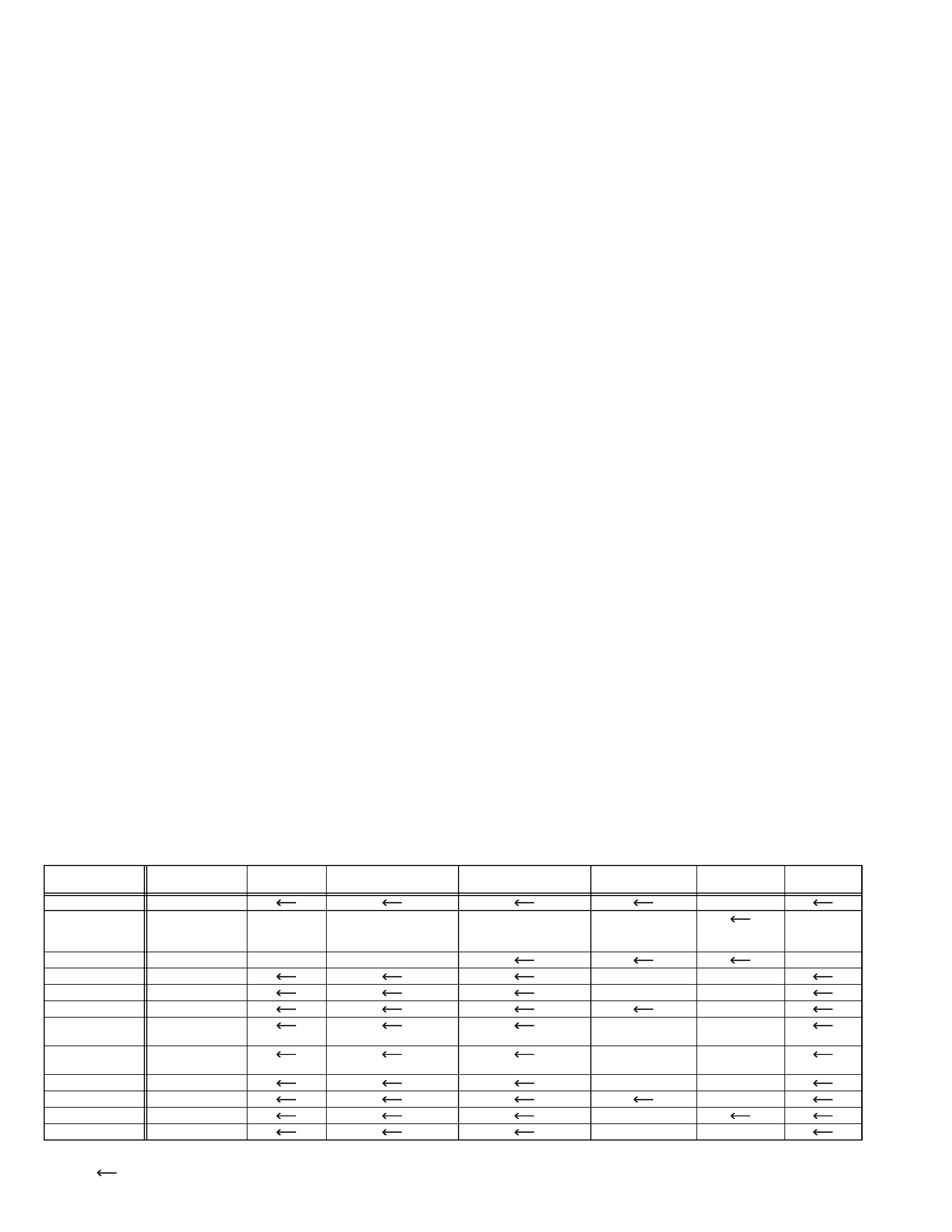
The following table indicates main different points between models HR-S5960EX,HR-S5961EX,HR-S5962EX, HR-S5963EX,HR-
S5963EX,HR-S5965EF,HR-S5965EK and HR-S5966EK.
NOTE:
Mark
is same as left.
MODEL
ITEM
HR-S5960EX
HR-S5961EX
HR-S5962EX
HR-S5963EX
HR-S5965EF
HR-S5965EK HR-S5966EK
POWER PLUG
CEE
3PIN
BODY COLOUR
PURE SILVER
BLACK
PURE SILVER & DARK
SILVER[WINDOW &
CASSETTE DOOR]
PURE SILVER & DARK
SILVER[WINDOW &
L/R COVER]
PURE SILVER
BLACK
RCU COLOUR
LIGHT GRAY
BLACK
LIGHT GRAY
BLACK
SCART CABLE
OPTIONAL
PROVIDED
OPTIONAL
MESECAM
USED(MANUAL)
USED(PB ONLY)
NOT USED
DECODER(L-2)
USED
NOT USED
BROADCASTING
STANDARD
B/G,D/K
L,L',B/G
I
STEREO
DECODER
NICAM/A2
NICAM(L,B/G)/
A2(B/G)
NICAM
RF OUT
USED
NOT USED
USED
VCR PLUS+
SHOWVIEW
VIDEO PLUS+
VPS
USED
NOT USED
OSD LANGUAGE 13 LANGUAGES
FRENCH
ENGLISH
(No.82961)1-3
SECTION 1
PRECAUTIONS
1.1 SAFTY PRECAUTIONS
Prior to shipment from the factory, JVC products are strictly in-
spected to conform with the recognized product safety and elec-
trical codes of the countries in which they are to be
sold.However,in order to maintain such compliance, it is equally
important to implement the following precautions when a set is
being serviced.
1.1.1 Precautions during Servicing
(1) Locations requiring special caution are denoted by labels
and inscriptions on the cabinet, chassis and certain parts of
the product.When performing service, be sure to read and
comply with these and other cautionary notices appearing in
the operation and service manuals.
(2) Parts identified by the
symbol and shaded (
) parts
are critical for safety.
Replace only with specified part numbers.
NOTE :
Parts in this category also include those specified to
comply with X-ray emission standards for products
using cathode ray tubes and those specified for com-
pliance with various regulations regarding spurious
radiation emission.
(3) Fuse replacement caution notice.
Caution for continued protection against fire hazard.
Replace only with same type and rated fuse(s) as specified.
(4) Use specified internal wiring. Note especially:
· Wires covered with PVC tubing
· Double insulated wires
· High voltage leads
(5) Use specified insulating materials for hazardous live parts.
Note especially:
· Insulation Tape
· PVC tubing
·Spacers
· Insulation sheets for transistors
· Barrier
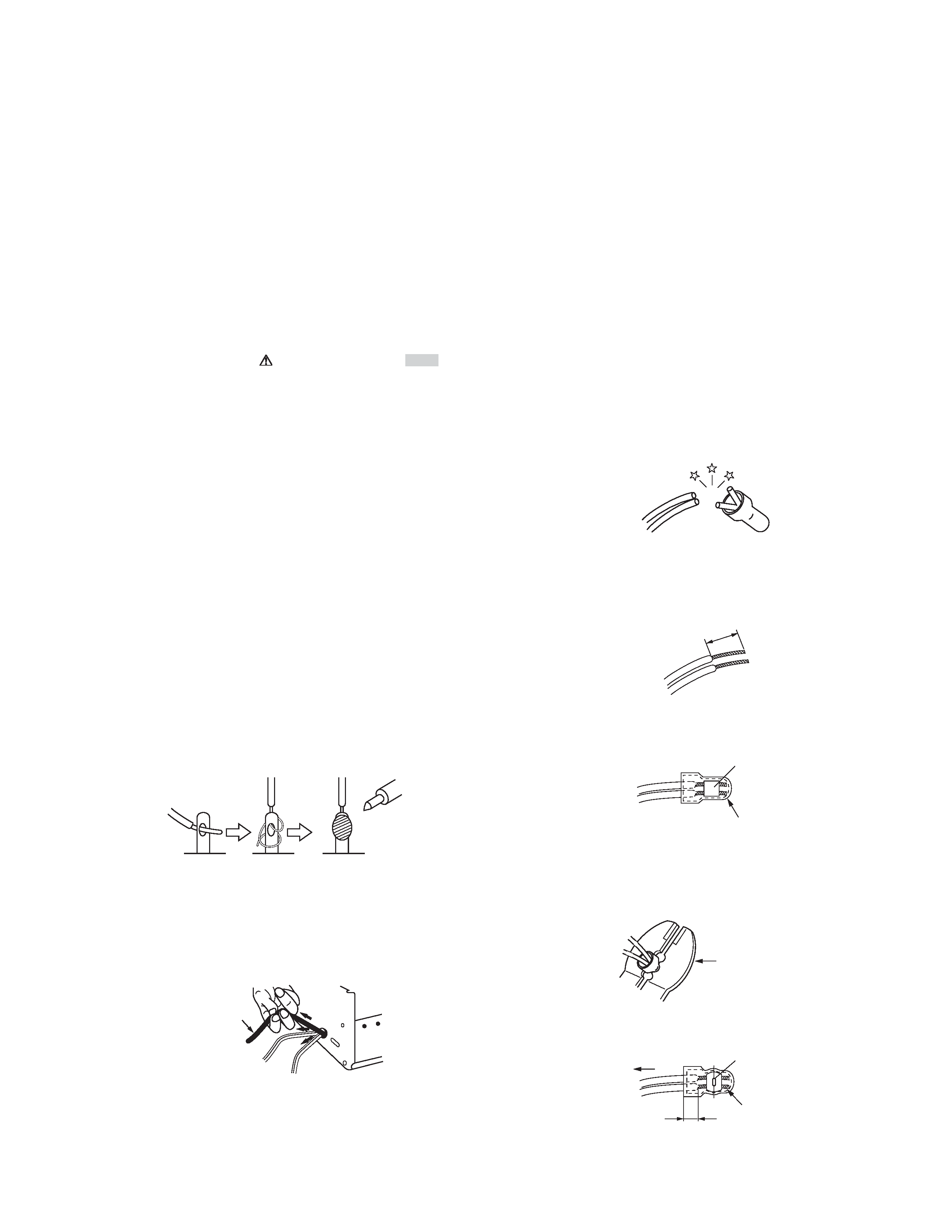
(6) When replacing AC primary side components (transformers,
power cords, noise blocking capacitors, etc.) wrap ends of
wires securely about the terminals before soldering.
Fig.1-1-1
(7) Observe that wires do not contact heat producing parts
(heatsinks, oxide metal film resistors, fusible resistors, etc.)
(8) Check that replaced wires do not contact sharp edged or
pointed parts.
(9) When a power cord has been replaced, check that 10-15 kg
of force in any direction will not loosen it.
Fig.1-1-2
(10) Also check areas surrounding repaired locations.
(11) Products using cathode ray tubes (CRTs)In regard to such
products, the cathode ray tubes themselves, the high volt-
age circuits, and related circuits are specified for compliance
with recognized codes pertaining to X-ray emission. Conse-
quently, when servicing these products, replace the cathode
ray tubes and other parts with only the specified parts. Under
no circumstances attempt to modify these circuits.Unautho-
rized modification can increase the high voltage value and
cause X-ray emission from the cathode ray tube.
(12) Crimp type wire connector
In such cases as when replacing the power transformer in
sets where the connections between the power cord and
power trans former primary lead wires are performed using
crimp type connectors, if replacing the connectors is un-
avoidable, in order to prevent safety hazards, perform care-
fully and precisely according to the following steps.
· Connector part number :E03830-001
· Required tool : Connector crimping tool of the proper
type which will not damage insulated parts.
· Replacement procedure
a) Remove the old connector by cutting the wires at a
point close to the connector.
Important : Do not reuse a connector (discard it).
Fig.1-1-3
b) Strip about 15 mm of the insulation from the ends of
the wires. If the wires are stranded, twist the strands
to avoid frayed conductors.
Fig.1-1-4
c) Align the lengths of the wires to be connected. Insert
the wires fully into the connector.
Fig.1-1-5
d) As shown in Fig.1-1-6, use the crimping tool to
crimp the metal sleeve at the center position. Be
sure to crimp fully to the complete closure of the
tool.
Fig.1-1-6
e) Check the four points noted in Fig.1-1-7.
Fig.1-1-7
Power cord
cut close to connector
15 mm
Connector
Metal sleeve
1.2
5
2.0
5.5
Crimping tool
Not easily pulled free
Crimped at approx. center
of metal sleeve
Conductors extended
Wire insulation recessed
more than 4 mm
1-4 (No.82961)
1.1.2
Safety Check after Servicing
Examine the area surrounding the repaired location for damage
or deterioration. Observe that screws, parts and wires have been
returned to original positions, Afterwards, perform the following
tests and confirm the specified values in order to verify compli-
ance with safety standards.
(1) Insulation resistance test
Confirm the specified insulation resistance or greater be-
tween power cord plug prongs and externally exposed
parts of the set (RF terminals, antenna terminals, video and
audio input and output terminals, microphone jacks, ear-
phone jacks, etc.).
See table 1 below.
(2) Dielectric strength test
Confirm specified dielectric strength or greater between
power cord plug prongs and exposed accessible parts of
the set (RF terminals, antenna terminals, video and audio
input and output terminals, microphone jacks, earphone
jacks, etc.). See Fig.1-1-11 below.
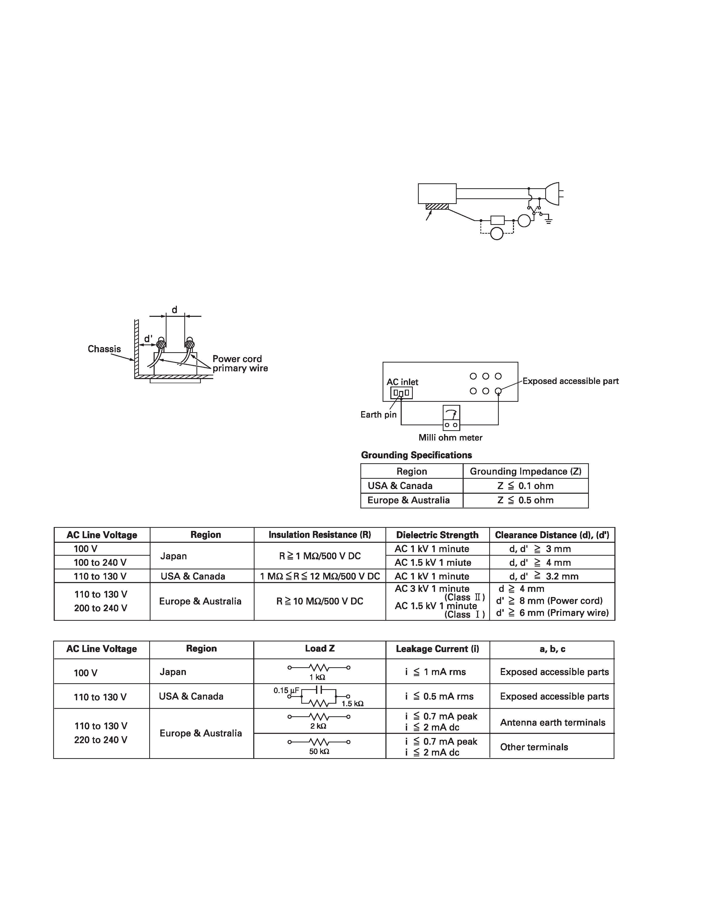
(3) Clearance distance
When replacing primary circuit components, confirm spec-
ified clearance distance (d), (d') between soldered termi-
nals, and between terminals and surrounding metallic
parts. See Fig.1-1-11 below.
Fig.1-1-8
(4) Leakage current test
Confirm specified or lower leakage current between earth
ground/power cord plug prongs and externally exposed ac-
cessible parts (RF terminals, antenna terminals, video and
audio input and output terminals, microphone jacks, ear-
phone jacks, etc.).
Measuring Method : (Power ON)
Insert load Z between earth ground/power cord plug
prongs and externally exposed accessible parts. Use an
AC voltmeter to measure across both terminals of load Z.
See Fig.1-1-9 and following Fig.1-1-12.
Fig.1-1-9
(5) Grounding (Class 1 model only)
Confirm specified or lower grounding impedance between
earth pin in AC inlet and externally exposed accessible
parts (Video in, Video out, Audio in, Audio out or Fixing
screw etc.).
Measuring Method:
Connect milli ohm meter between earth pin in AC inlet and
exposed accessible parts. See Fig.1-1-10 and grounding
specifications.
Fig.1-1-10
Fig.1-1-11
Fig.1-1-12
NOTE :
These tables are unofficial and for reference only. Be sure to confirm the precise values for your particular country and locality.
ab
c
V
A
Externally
exposed
accessible part
Z
(No.82961)1-5
SECTION 2
SPECIFIC SERVICE INSTRUCTIONS
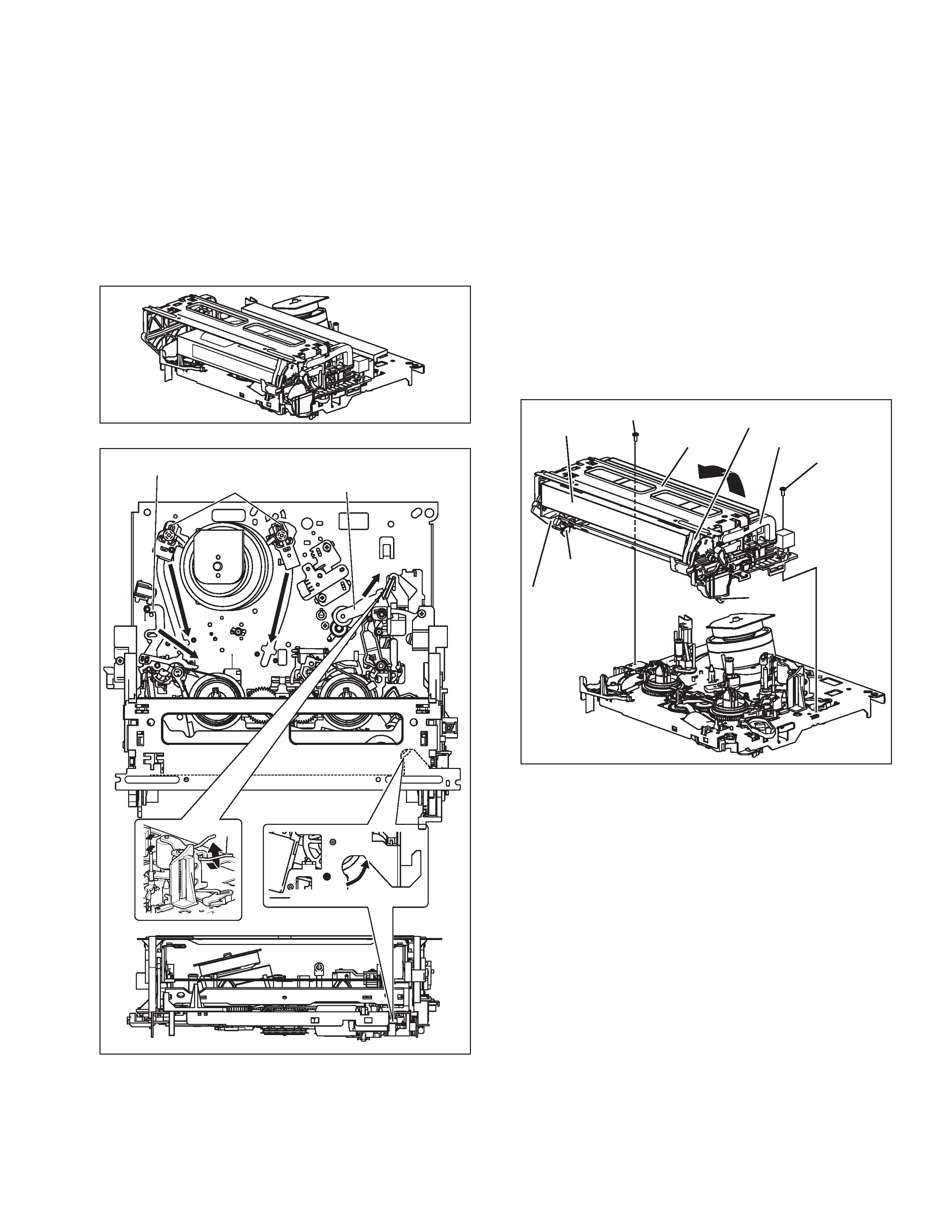
2.1 Manually removing the cassette tape
If you cannot remove the cassette tape which is loaded because
of any electrical or mechanical failures, manually remove it by
taking the following steps.
(1) Unplug the power cord plug from the power outlet.
(2) Refer to the disassembly procedure of the VCR and per-
form the disassembly of the major parts before removing
the mechanism assembly. (See Fig. 2-1a)
Fig.2-1a
Fig.2-1b
(3) Unload the pole base assembly by manually turning the
gear of the loading motor until the pole base assembly is
hidden behind the cassette lid. In doing so, hold the tape by
the hand to keep the slack away from any grease. (See
Fig.2-1b )
In case of mechanical failures, while keeping the ten-
sion arm assembly free from tension, pull out the tape
on the pole base assembly. Take the spring(a) of the
pinch roller arm assembly off the hook, and detach it
from the tape.
(4) Remove the screw (a) of the side frame (L/R).
(5) Hold the slack tape and cassette cover together, lift the
cassette tape, top frame, cassette holder and side frames
(L, R) together from the rear and remove them by dis-en-
gaging the hooks (a) and (b).
Fig.2-1c
(6) Take up the slack of the tape into the cassette. This com-
pletes removal of the cassette tape.
Pole base assembly
Tension arm assembly
Pinch roller arm assembly
Direction of unloading
Spring(a)
Screw(a)
Screw(a)
Top frame
Cassette tape
Cassette holder
Side frame(R)
Side frame(L)
Hook(a)
Hook(b)