G E N E R A L
Power requirement : AC 220 V 240 V
Ó, 50 Hz/60 Hz
Power consumption : on : 18 W, off : 3.3 W
Operating Temperature : 5°C to 40°C
Storage Temperature: 20°C to 60°C
Operating position : Horizontal only
Dimensions (WxHxD) : 400 mm x 94 mm x 270 mm
Format : S-VHS, VHS PAL standard
Maximum recording time :
(SP) : 240 min. with E-240 video cassette
(LP) : 480 min. with E-240 video cassette
V I D E O / A U D I O
Signal system : PAL-type colour signal and CCIR monochrome
signal, 625 lines/50 fields
Recording system : DA4 (Double Azimuth) helical scan system
Signal-to-noise ratio : 45 dB
Horizontal resolution : 250 lines (VHS)
400 lines (S-VHS)
Frequency range : 70 Hz to 10,000 Hz (Normal audio)
20 Hz to 20,000 Hz (Hi-Fi audio)
Input/Output : 21-pin SCART connectors
(IN/OUT x 1, IN x 1)
RCA connectors
(VIDEO IN x 1, AUDIO IN x 1, AUDIO OUT x 1)
Weight : 3.2 kg
T U N E R / T I M E R
TV channel storage capacity : 99 positions (+AUX position)
Tuning system :Frequency synthesized tuner
Channel coverage : VHF 44.5 MHz 143 MHz/
143 MHz 470 MHz/
UHF 470 MHz 862 MHz
Aerial output : UHF channels 22 69 (Adjustable)
Memory backup time : Approx. 10 min.
A C C E S S O R I E S
Provided accessories : RF cable, Infrared remote control unit,
`AA' battery x 2
Specifications shown are for SP mode unless otherwise specified.
E.& O.E. Design and specifications subject to change without notice.
SERVICE MANUAL
No.82924
June 2002
HR-S5956EK, HR-S6955EK
Regarding service information other than these sections, refer to the HR-S5955EK service manual (No.82922).
Also, be sure to note important safety precautions provided in the service manual.
VIDEO CASSETTE RECORDER
This service manual is printed on 100% recycled paper.
COPYRIGHT © 2002 VICTOR COMPANY OF JAPAN, LTD
SPECIFICATIONS (The specifications shown pertain specifically to the model HR-S6955EK)
HR-S5956EK, HR-S6955EK V15S0
TV PR +
TV PR
T
V
TV
+
0000
STOP
FIN
MENU
OK
TV/VCR
DAILY/QTDN.
VPS/PDC
AUX
WEEKLY/HEBDO
PROG
30 SEC
:
AUDIO
12
3
4
6
5
7
8
9
0
DATE
START
DEBUT
PR
4
1
3
ENTER/ENTR
EE
EXPRESS
TV
?
2
/
LP00000-000
VCR/ TV
/I
VCR
S-VHS
REVIEW
24H EXPRESS
1 3
2
PR -- /
+
PUSH / TURN
S-VHS
ET
VIDEO
(MONO)
L
AUDIO R
625
--:--
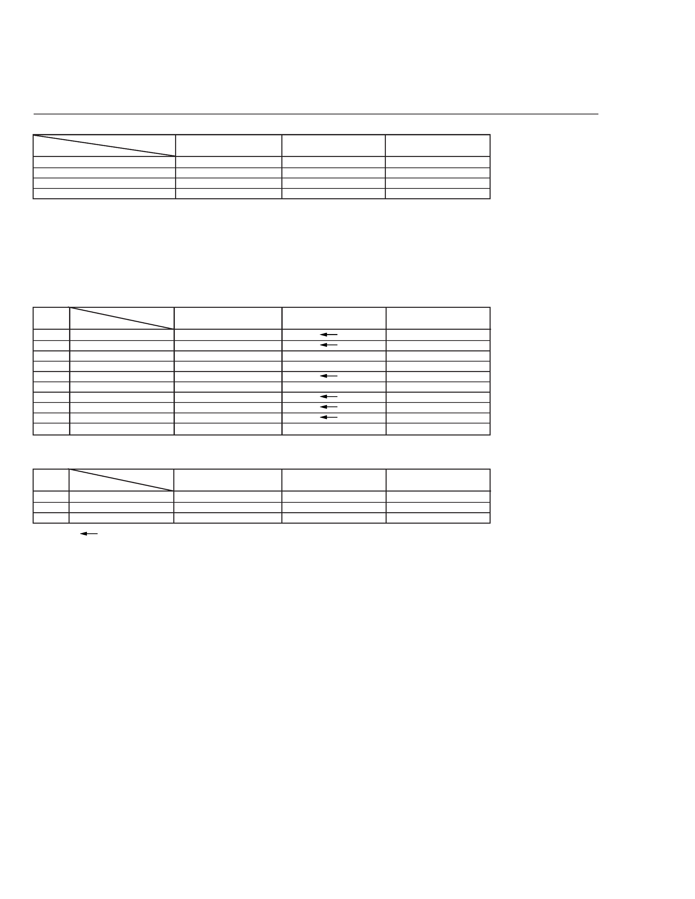
TABLE OF CONTENTS
The following table indicate main different points between models HR-S5955EK, HR-S5956EK and HR-S6955EK.
MODEL
HR-S5955EK
ITEM
BODY COLOR
PURE SILVER
BLACK
PURE SILVER
DISPLAY WINDOW COLOR
METALLIC GRAY
BLACK
PURE SILVER
REMOTE CONTROLLER COLOR
LIGHT GRAY
BLACK
LIGHT GRAY
ADVANCED JOG
NOT USED
NOT USED
USED
HR-S5956EK
DIFFERENT TABLE .............................................................................................................................................................................................. 1 only
5. PARTS LIST (5-1 to 5-3)
5.1
PACKING AND ACCESSORY ASSEMBLY <M1> ................................................................................................................................. 5-1
5.2
FINAL ASSEMBLY <M2> ....................................................................................................................................................................... 5-2
HR-S6955EK
The following table indicate different parts number between models HR-S5955EK, HR-S5956EK and HR-S6955EK.
PACKING AND ACCESSORY ASSEMBLY<M1>
PACKING AND ACCESSORY ASSEMBLY<M1> is indicated on the parts list.
FINAL ASSEMBLY<M2>
FINAL ASSEMBLY<M2> is indicated on the parts list.
MAIN BOARD ASSEMBLY<03>
REF
NO.
!
MODEL
ITEM
PW1
MAIN BOARD ASSY
LPA10160-08E
LPA10160-10C
IC3003 IC(EEPROM)
LPN0738-003A-01
LPN0759-001A-03
B3005 MG RESISTOR
--
--
NRSA02J-0R0X
R3245 MG RESISTOR
--
--
NRSA02J-333X
R7025 MG RESISTOR
NRSA02J-472X
--
R7034 MG RESISTOR
--
--
NRSA-02J-272X
S7014 TACT SWITCH
QSW0456-002Z
--
S7015 TACT SWITCH
QSW0456-002Z
--
! TB1
TERMINAL BOARD(PAL) LP20317-011B
LP20317-011A
CN7001 FPC CONNECTOR, ADV.JOG
--
--
QGF1207C1-04
HR-S5955EK
HR-S5956EK
HR-S6955EK
Note: Mark
is same as left.
Mark -- is not used.
1
ADV. JOG BOARD ASSEMBLY<38>
REF
NO.
!
MODEL
ITEM
PW1
ADV.JOG BOARD ASSY
--
--
LPA20013-07A
UN7001 ROTARY ENCODER
--
--
QSW0905-001
CN7003 FPC CONNECTOR
--
--
QGF1207F1-04
HR-S5955EK
HR-S5956EK
HR-S6955EK
5-1
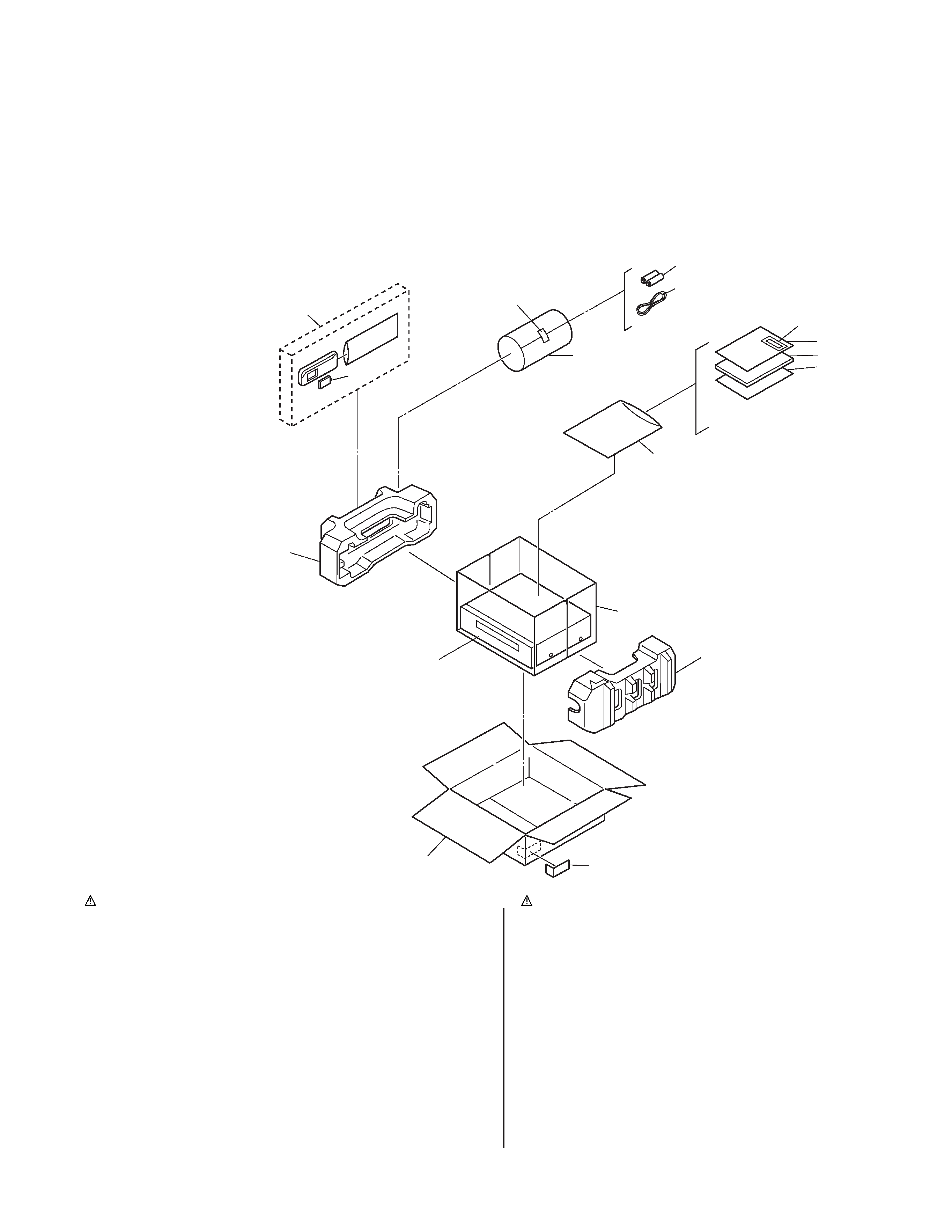
5.1
PACKING AND ACCESSORY ASSEMBLY <M1>
The instruction manual to be provided with this product will differ according to the destination.
******************************
PACKING AND ACCESSORY ASSEMBLY
<M1>
301
LP30855-004A
PACKING CASE
302
LP30909-001C
CUSHION ASSY
303
PQM30021-93
POLY BAG
306
LP20878-014A
REMOTE CONTROLLER,HR-S6955EK
LP20878-015A
REMOTE CONTROLLER,HR-S5956EK
306A
LP40610-001A
COVER(BATTERY),HR-S5956EK
LP40610-003A
COVER(BATTERY),HR-S6955EK
307
BATTERY,X2("AA"TYPE)
308
QPC02202230P
POLY BAG
---------------
-----------------------
---------------------------------------------------- -
------------- ---
-----------------------
----------------------------------------------------- -
#
REF No. PART No.
PART NAME, DESCRIPTION
#
REF No.
PART No.
PART NAME, DESCRIPTION
301
302
302
SPEC OF BARCODE
FINAL ASSY <M2>
ADHESIVE TAPE
307
312
308
306
306A
303
319
311
317
SPEC OF BARCODE
310
! 310
LPT0653-001A
INST.BOOK(EN),HR-S5956EK
!
LPT0693-001A
INST.BOOK(EN),HR-S6955EK
311
QPC02503530P
POLY BAG
312
PEAC0300-02
RF CABLE
317
BT-54008-2
GUARANTY CARD
319
LYT0194-001B
Q.CARD(JUK)
******************************
SECTION 5
PARTS LIST
SAFETY PRECAUTION
Parts identified by the
! symbol are critical for safety. Replace only with specified part numbers.
JS3001
JS
30
01
D3
00
1
Q3
00
3
Q3
00
2
CN
50
01
"Z"
f
b
b
d'
c'
c
e
b
c'
c
a
h
h
b
b
b
d
c'
c'
d'
e
f
f
f
f
f
f
f
a
g
g
532
517
REAR SIDE
ONLY USED FOR HR-S6955EK
ONLY USED FOR
HR-S6955EK
504
512
502
503
503
MAIN BOARD ASSY<03>
523
511
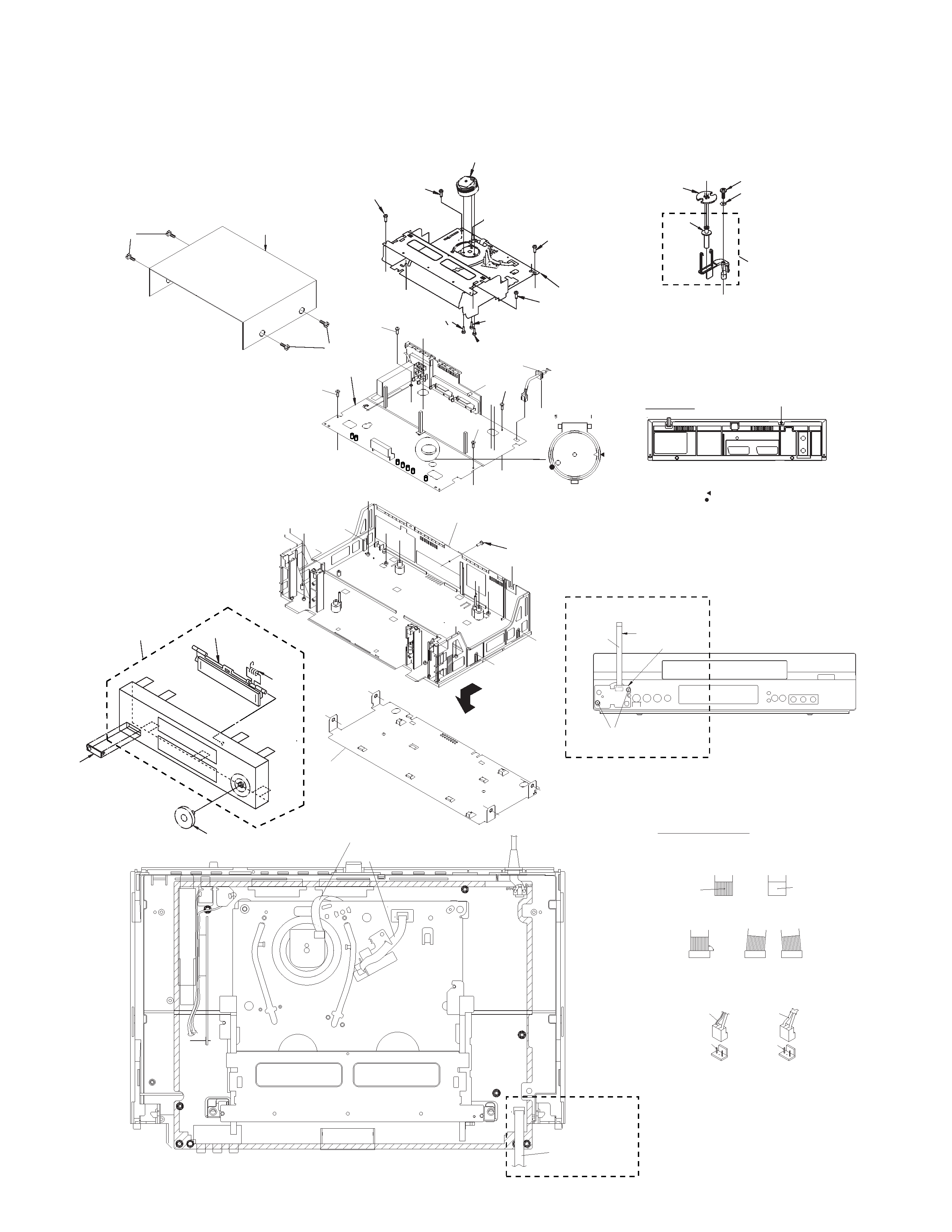
Insert the bushing of POWER CORD
so as not to twist the cord.
Accord the position of V gap on R. Encoder and PWB silk " ".
<Phase alignment>
Accord the position of Boss on R. Encoder and PWB silk " ".
For the prevention of the DRUM FPC damage.
When you attach the MECHA UNIT on B. CHASSIS.
Attach the MECHA UNIT after the positioning boss "z" of the
B. CHASSIS is matched to the positioning hole of the MECHA UNIT.
533
533
533
Right side
Back side
OK
NG
CN
electrode side
supporting side
Except U/U(C)/JPN
NOTE
CN
CN
1. Insert direction of FCC WIRE as follows.
2. FFC WIRE and DRUM FPC WIRE should be insert as follows.
3. Insert direction of POWER CORD.
90
NEUTRAL
WHITE LINE
CN5001
BLUE
NEUTRAL
CN5001
U/U(C)/JPN
a
d
d
g
e
MECHANISM ASSY<M4>
505
510
515
510
510
516
516
515
NOTE) After attached ROLLER ARM ASS'Y,
tighten screw(S3g) with slit washer(W3a).
NOTE) When attaching ROLLER ARM ASS'Y,
attach the hook(L3c) before the spring(P3a).
NOTE) INERTIA PLATE should be attached so as to ser small
diameter of central round hole above.
k
520
522
521
519A
519
g
501A
501
529 [HR-S6955EK]
534
501B
CN7003
WR4
To main CN7001
Front panel back side
ADV. JOG
BOARD
ASSY<38>
530
BACK SIDE
CN5001
CN2001
CN7001
CN7105
CN7102
For JOG
CN501
1
1
From CAPSTAN MDA
Right side
Right side
from FRONT PANEL
Right side
DRUM
A/C HEAD
BEWARE OF BOGUS PARTS
Parts that do not meet specifications may
cause trouble in regard to safety and per-
formance. We recommend that genuine JVC
parts be used.
5.2
FINAL ASSEMBLY <M2>
5-2

******************************
FINAL ASSEMBLY
<M2>
! 501
LP10427-020B
FRONT PANEL ASSY,HR-S6955EK
!
LP10434-014A
FRONT PANEL ASSY,HR-S5956EK
501A
LP20961-015C
CASSETTE DOOR,HR-S6955EK
LP20961-029A
CASSETTE DOOR,HR-S5956EK
501B
PQ46448
TORSION SPRING
! 502
LP10013-051B
TOP COVER,HR-S6955EK
!
LP10013-061B
TOP COVER,HR-S5956EK
503
QYTDSF3010M
SCREW,X4,TOP COVER(SIDE),HR-S5956EK
QYTDSF3010R
SCREW,X4,TOP COVER(SIDE),HR-S6955EK
504
QYTDSF3010M
SCREW,TOP COVER(REAR)
505
PDV2544A
DRUM ASSY
510
QYSPSPD3008Z
SCREW,X3,DRUM
! 511
LP10108-001H
BOTTOM CHASSIS
! 512
LP10014-002C
BOTTOM COVER
515
QYTDSF4012Z
SCREW,X2,MECHA
516
QYSPSFG3010Z
SCREW,X2,MECHA
! 517
QMP51K0-170-K
POWER CORD
519
LP40370-001F
ROLLER ARM ASSY
519A
PDM4311A-1
ROLLER ASSY
520
PQ45160
INERTIA PLATE
521
PQM30017-51
SLIT WASHER
522
QYSLSF2060D
SCREW
523
QYTDSF3010M
SCREW,T.BOARD
529
LP31019-005D
KNOB ASSY,HR-S6955EK
530
QYTPSFG2608Z
SCREW,X2,ADV.JOG,HR-S6955EK
532
QYTDSF3010Z
SCREW,MAIN
533
DPSF3010Z
SCREW,X3,MAIN
534
LP30871-003B
CAP(JACK),HR-S6955EK
LP30871-005B
CAP(JACK),HR-S5956EK
WR4
QUQ212-0414CG
FFC WIRE,ADV.JOG,HR-S6955EK
#
REF No. PART No.
PART NAME, DESCRIPTION
5-3
(VP)-V15S0
E. & O. E. No.82924