SERVICE MANUAL
No. 82853
April 2001
HM-HDS1U
SPECIFICATIONS
HDD / VHS DUAL RECORDER
Printed in Japan
This service manual is printed on 100% recycled paper.
COPYRIGHT © 2001 VICTOR COMPANY OF JAPAN, LTD.
HM-HDS1U
No.
82853
JVC SERVICE & ENGINEERING COMPANY OF AMERICA
DIVISION OF JVC AMERICAS CORP.
Head office
East Coast
Midwest
West Coast
Atlanta
Hawaii
:
:
:
:
:
:
1700 Valley Road Wayne, New Jersey 07470-9976
10 New Maple Avenue Pine Brook, New Jersey 07058-9641
705 Enterprise Street Aurora, Illinois 60504-8149
5665 Corporate Avenue Cypress, California 90630-0024
1500 Lakes Parkway Lawrenceville, Georgia 30043-5857
2969 Mapunapuna Place Honolulu, Hawaii 96819-2040
(973)315-5000
(973)396-1000
(630)851-7855
(714)229-8011
(770)339-2582
(808)833-5828
JVC CANADA INC.
Head office
Montreal
Vancouver
:
:
:
21 Finchdene Square Scarborough, Ontario M1X 1A7
16800 Rte Trans-Canadienne, Kirkland, Quebec H9H 5G7
13040 Worster Court Richmond, B.C. V6V 2B3
(416)293-1311
(514)871-1311
(604)270-1311
S40895-03
DIGITPURE TECHNOLOGY
S-VHS ET
S-VHS
HDD
OK
HM-HDS1
MENU
REC LINK
CH
NAVI
STOP
PLAY
PAUSE
REC
REW
FEW
A. DUB
EJECT
VIDEO
PAUSE
S-VIDEO
(M) L AUDIO R
POWER
F - 1
12
3
4
56
78
9
0
2
1
4
3
>
<
1
2
+
GENERAL
Power requirement
: AC 120 V`, 60 Hz
Power consumption
Power on
: 45 W
Power off
: 14 W
Temperature
Operating
: 5°C to 40°C (41°F to 104°F)
Storage
: 20°C to 60°C (4°F to 140°F)
Operating position
: Horizontal only
Dimensions (WxHxD) : 435 mm x 124 mm x 385 mm
(17-1/16" x 4-15/16" x 15-3/16")
Weight
: 7.4 kg (16.4 lbs)
Input/Output
: RCA connectors: (IN x 1, OUT x 2)
S-Video connectors:(IN x 1, OUT x 2)
HDD DECK VIDEO/AUDIO
Video format
: MPEG2 (VBR)
Audio format
: MPEG1 Layer2
Maximum recording time
(SP)
: 14 hours
(LP)
: 20 hours
(EP)
: 28 hours
(SEP)
: 40 hours
VHS DECK VIDEO/AUDIO
Signal system
: NTSC-type colour signal and EIA monochrome
signal, 525 lines/60 fields
Recording system
: DA4 (Double Azimuth) head helical scan system
Format
: S-VHS/VHS NTSC standard
Signal-to-noise ratio
: 45 dB
Horizontal resolution
: 240 lines (VHS)
400 lines (S-VHS)
Frequency range
: 70 Hz to 10,000 Hz (Normal audio)
20 Hz to 20,000 Hz(Hi-Fi audio)
Maximum recording time
(SP)
: 210 min. with ST-210 video cassette
(EP)
: 630 min. with ST-210 video cassette
TUNER
Tuning system
: Frequency-synthesized tuner
Channel coverage
VHF
: Channels 213
UHF
: Channels 1469
CATV
: 113 Channels
TIMER
Clock reference
: Quartz
Program capacity
: 1-year programmable timer/
16 programs each on the VHS and
HDD deck
Memory backup time
: Approx. 60 min.
ACCESSORIES
Provided accessories
: RF cable (F-type),
Infrared remote control unit, "AA"
battery x 2,
Audio/Video Cable,
S-Video cable (4-pin),
Controller
Specifications shown are for SP mode unless otherwise specified.
E. & O.E. Design and specifications subject to change without notice.
1
Hard Disk Drive (HDD)
1. Hard Disk Drive (HDD) Handling Precautions
The HDD is a precision device for use in reading and writing a large amount of data on or from a disk rotating at
a high speed. If it is not handled carefully, either abnormal operation may result or it may not be possible to read
data. The HDD is sensitive to the following items and special care is required in safeguarding against them when
handling an HDD. Also take care in handling a set incorporating an HDD.
1. Vibrations and impacts
2. Static electricity
3. Rough handling
1.1
Handling in transport, etc.
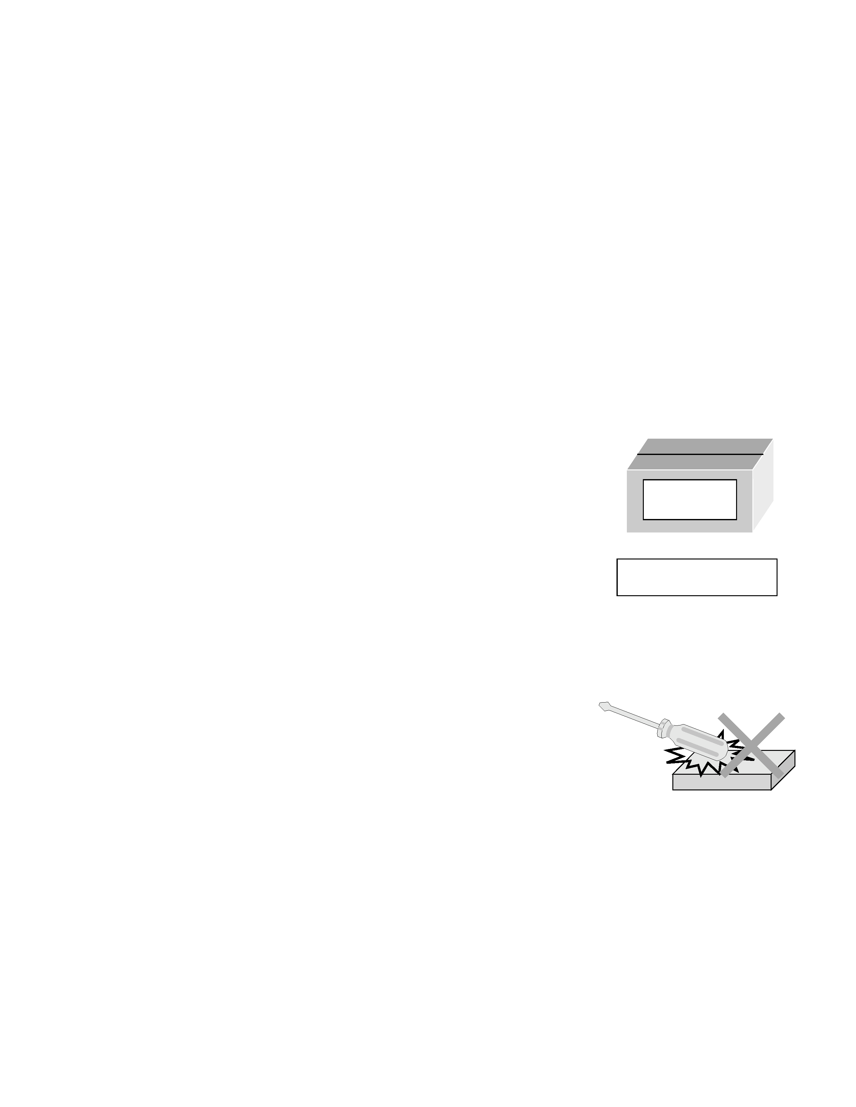
s Be sure to place the HDD in the manufacturer's specified package
carton before transport.
s When receiving a package containing an HDD, check that the pack-
age carton is not damaged (such as having holes in the carton,
crushed corners, etc.).
s Do not impact the packaging carton when loading or unloading it.
s It is not permitted to use the inner package carton only for transport-
ing an HDD.
s Do not stack package cartons one upon another.
1.2
Handling an HDD in the stand-alone status
s When handling an HDD on a hard workbench, place an antistatic
mat (rubber sheet) or similar object on the hard surface (to prevent
any impacts occurring between the HDD and bench).
s Do not stack the HDDs one upon another.
s Do not knock an HDD with a hard object (such as a screwdriver).
s Do not place an HDD on its side panel without using a support (do
not place an HDD in an unstable position).
1.3
Handling the installation of an HDD
s Place antistatic mats or similar sheets on all of the surfaces on which work is conducted or when the HDD
is transported.
s Do not permit the HDD to knock against the set's brackets.
s When screwing the brackets, be careful not to knock the HDD. When using a power screwdriver, use a low-
shock model and arrange the tightening torque properly.
s When mounting an HDD in a computer, take care not to apply excessive force to the brackets.
HDD
Do not throw or
drop packages.
Be sure to package and
transport the HDDs correctly.
2
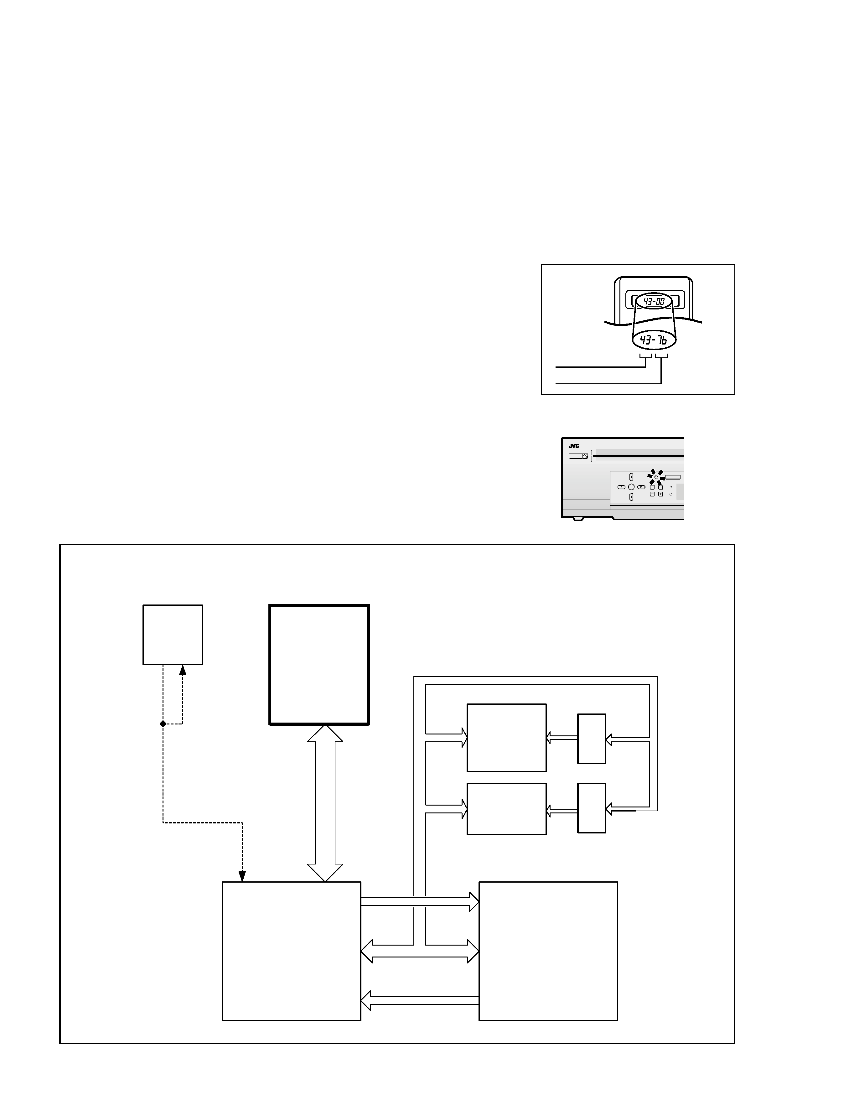
2. In Case of an HDD Failure
When a computer AC cord is plugged into a power outlet, the boot loader is read from the IC8204 (8M FLASH
ROM), which activates the HDD and reads the system files in the HDD before getting ready for operation. In
consequence, the computer cannot be turned on if the HDD fails.
In case a failure of the HDD is in doubt, use the following procedure to switch the main power of the set ON using
the VHS section alone, by bypassing the HDD operation check.
(1) With the computer in the remote control standby status, trans-
mit code 7b from the remote jig for more than 2 seconds.
(2) The BS digital reservation button on the computer blinks, indi-
cating that the power supply can be switched ON.
(3) When the code 7B is transmitted again from the remote jig,
the button stops blinking and its function is canceled.
Initial mode
Data code
Custom code
43: A code
52: B code
HDD
OK
HM-HDS1
POWER
BS DIGIATL
CHANNEL
Blinks.
ASIC_IF
MPEG_DEC
40GB
HDD
IC8201
IC8001
8M FLASH
OPEN
IC8204
IC8205
IC8206
IC8207
DVD 0_:7_
VIO 0:7
IDE 40PIN
AD 0:31
AD 4:11
AD 12:19
LADO
4:11
LADO
12:19
AD 0:15
AD 16:31
AD 4:19
VHS
SYSCON
HOSTD
A
T
A
KB
US_IN
KB
US_OUT
Address
Latch
Address
Latch
E:08 is displayed in the
case of a
communication error
with the VHS SYSCON
Firmware
HDD driver
Navigation information
boot loader
VHS Navi
back up
<Reference>

Hard Disk Drive (HDD)
Important Safety Precautions
INSTRUCTIONS
1. DISASSEMBLY
1.1 HOW TO REMOVE THE MAJOR PARTS ..................................................... 1-1
1.1.1 Introduction .................................................................................... 1-1
1.2 HOW TO READ THE DISASSEMBLY AND ASSEMBLY .............................. 1-1
1.3 DISCONNECTION OF CONNECTORS (WIRES) ........................................ 1-1
1.4 SCREWS USED CABINET COMPONENTS AND BOARD ASSEMBLIES .. 1-1
1.5 HOW TO REMOVE THE MAJOR PARTS <COM section> ........................... 1-2
1.5.1 Disassembly flow chart .................................................................. 1-2
1.5.2 Disassembly/assembly method <COM section> ............................ 1-2
1.6 HOW TO REMOVE THE MAJOR PARTS <VHS section> ............................ 1-4
1.6.1 Disassembly flow chart .................................................................. 1-4
1.6.2 DIsassembly/assembly method <VHS section> ............................ 1-4
1.7 HOW TO REMOVE THE MAJOR PARTS <HDD section> ............................ 1-6
1.7.1 Disassembly flow chart .................................................................. 1-6
1.7.2 DIsassembly/assembly method <HDD section> ............................ 1-6
1.8 SERVICE POSITIONS .................................................................................. 1-7
1.8.1 Service position <VHS SIDE> ........................................................ 1-7
1.8.2 Service position <HDD side> ......................................................... 1-8
1.9 MECHANISM SERVICE MODE .................................................................... 1-9
1.9.1 How to set the "MECHANISM SERVICE MODE" .......................... 1-9
1.10 CONNECTION .................................................................................. 1-10
1.11 EMERGENCY DISPLAY FUNCTION ................................................ 1-12
1.11.1 Displaying the emergency information ........................................ 1-12
1.11.2 Clearing the emergency history ................................................... 1-12
1.11.3 Emergency content description ................................................... 1-13
1.11.4 Emergency detail information 1 ................................................. 1-14
1.11.5 Emergency detail information 2 ................................................. 1-15
2. MECHANISM ADJUSTMENT (VHS)
2.1 BEFORE STARTING REPAIR AND ADJUSTMENT ..................................... 2-1
2.1.1 Precautions .................................................................................... 2-1
2.1.2 Checking for Proper Mechanical Operations .................................. 2-1
2.1.3 Manually Removing the Cassette Tape .......................................... 2-1
2.1.4 Jigs and Tools Required for Adjustment ......................................... 2-2
2.1.5 Maintenance and Inspection .......................................................... 2-3
2.2 REPLACEMENT OF MAJOR PARTS ........................................................... 2-6
2.2.1 Before Starting Disassembling (Phase matching between mechanical parts) . 2-6
2.2.2 How to Set the Mechanism Assembling Mode ............................... 2-6
2.2.3 Cassette Holder Assembly ............................................................. 2-6
2.2.4 Pinch Roller Arm Assembly ............................................................ 2-8
2.2.5 Guide Arm Assembly and Press Lever Assembly .......................... 2-8
2.2.6 Audio Control Head ........................................................................ 2-8
2.2.7 Loading Motor ................................................................................ 2-8
2.2.8 Capstan Motor ................................................................................ 2-9
2.2.9 Pole Base Assembly (supply or take-up side) ................................ 2-9
2.2.10 Rotary Encoder .......................................................................... 2-10
2.2.11 Clutch Unit ................................................................................. 2-10
2.2.12 Change Lever Assembly, Direct Gear, Clutch Gear and Coupling Gear 2-10
2.2.13 Link Lever ................................................................................... 2-11
2.2.14 Cassette Gear, Control Cam and Worm Gear ........................... 2-11
2.2.15 Control Plate .............................................................................. 2-11
2.2.16 Loading Arm Gear (supply or take-up side) and Loading Arm Gear Shaft 2-12
2.2.17 Take-up Lever, Take-up Head and Control Plate Guide ............. 2-13
2.2.18 Capstan Brake Assembly ........................................................... 2-13
2.2.19 Sub Brake Assembly (take-up side) ........................................... 2-13
2.2.20 Main Brake Assembly (take-up side), Reel Disk (take-up side) and
Main Brake Assembly (supply side) .................................................... 2-13
2.2.21 Tension Brake Assembly, Reel Disk (supply side) and Tension Arm Assembly 2-14
2.2.22 Idler Lever, Idler Arm Assembly ................................................. 2-14
2.2.23 Stator Assembly ......................................................................... 2-14
2.2.24 Rotor Assembly .......................................................................... 2-14
2.2.25 Upper Drum Assembly ............................................................... 2-15
2.3 COMPATIBILITY ADJUSTMENT ................................................................ 2-16
2.3.1 Checking/Adjustment of FM Waveform Linearity ......................... 2-16
2.3.2 Checking/Adjustment of the Height and Tilt of the Audio Control Head 2-17
2.3.3 Checking/Adjustment of the Audio Control Head Phase (X-Value) .. 2-17
2.3.4 Checking/Adjustment of the Standard Tracking Preset ................ 2-18
2.3.5 Checking/Adjustment of the Tension Pole Position ...................... 2-18
3. ELECTRICAL ADJUSTMENT (VHS)
3.1 PRECAUTION ............................................................................................... 3-1
3.1.1 Required test equipments .............................................................. 3-1
3.1.2 Required adjustment tools ............................................................. 3-1
3.1.3 Color (colour) bar signal,Color (colour) bar pattern ....................... 3-1
3.1.4 Switch settings and standard precautions ...................................... 3-1
3.1.5 EVR Adjustment ............................................................................. 3-1
3.2 SERVO CIRCUIT .......................................................................................... 3-2
3.2.1 Switching point ............................................................................... 3-2
3.2.2 Slow tracking preset ....................................................................... 3-2
TABLE OF CONTENTS
Section
Title
Page
Section
Title
Page
3.3 VIDEO CIRCUIT ........................................................................................... 3-2
3.3.1 D/A level ......................................................................................... 3-2
3.3.2 EE Y level ....................................................................................... 3-3
3.3.3 PB Y level (S-VHS / VHS) .............................................................. 3-3
3.3.4 REC color (colour) level ................................................................. 3-3
3.3.5 Video EQ (Frequency response) .................................................... 3-4
3.3.6 AUTO PICTURE initial setting ........................................................ 3-4
3.4 DIGITAL CIRCUIT ......................................................................................... 3-4
3.4.1 HDD EE Y level .............................................................................. 3-4
3.4.2 HDD PB Y level .............................................................................. 3-5
3.4.3 HDD PB C burst level ..................................................................... 3-5
3.5 AUDIO CIRCUIT ........................................................................................... 3-5
3.5.1 Audio REC FM ............................................................................... 3-5
3.6 DEMODULATOR CIRCUIT ........................................................................... 3-6
3.6.1 Input level ....................................................................................... 3-6
3.6.2 Stereo VCO .................................................................................... 3-6
3.6.3 Stereo filter ..................................................................................... 3-6
3.6.4 Separation - 1 ................................................................................. 3-6
3.6.5 Separation - 2 ................................................................................. 3-7
3.6.6 SAP VCO ....................................................................................... 3-7
4. CHARTS AND DIAGRAMS
NOTES OF SCHEMATIC DIAGRAM ................................................................... 4-1
CIRCUIT BOARD NOTES .................................................................................... 4-2
4.1 BOARD INTERCONNECTIONS ................................................................... 4-3
4.2 SWITCHING REGULATOR AND REGULATOR SCHEMATIC DIAGRAMS ........... 4-5
4.3 VIDEO/AUDIO SCHEMATIC DIAGRAM ....................................................... 4-7
4.4 SYSTEM CONTROL SCHEMATIC DIAGRAM ............................................. 4-9
4.5 VIDEO I/O SWITCH SCHEMATIC DIAGRAM ............................................ 4-13
4.6 AUDIO I/O SCHEMATIC DIAGRAM ............................................................ 4-15
4.7 CONNECTION SCHEMATIC DIAGRAM .................................................... 4-17
4.8 TUNER SCHEMATIC DIAGRAM ................................................................ 4-19
4.9 3D DIGITAL/2M SCHEMATIC DIAGRAM ................................................... 4-21
4.10 TERMINAL SCHEMATIC DIAGRAM ........................................................ 4-23
4.11 DEMODULATOR SCHEMATIC DIAGRAM ............................................... 4-25
4.12 S-SUB SCHEMATIC DIAGRAM ............................................................... 4-27
4.13 ON SCREEN SCHEMATIC DIAGRAM ..................................................... 4-29
4.14 EJECT SW, DIAPLAY, JACK, LED/SW AND LED SCHEMATIC DIAGRAMS .. 4-31
4.15 DIGITAL P.SUP SCHEMATIC DIAGRAM .................................................. 4-33
4.16 DIGITAL VIDEO SCHEMATIC DIAGRAM ................................................. 4-35
4.17 DIGITAL AUDIO SCHEMATIC DIAGRAM ................................................ 4-37
4.18 DIGITAL MPEG DEC SCHEMATIC DIAGRAM ......................................... 4-39
4.19 DIGITAL MPEG ENC SCHEMATIC DIAGRAM ......................................... 4-41
4.20 DIGITAL ASIC IF SCHEMATIC DIAGRAM ............................................... 4-43
4.21 SWITCHING REGULATOR AND REGULATOR CIRCUIT BOARDS ....... 4-45
4.22 3D DIGITAL/2M AND S-SUB CIRCUIT BOARDS .................................... 4-47
4.23 TERMINAL CIRCUIT BOARD .................................................................. 4-48
4.24 EJECT SW, DISPLAY, LED/SW, JACK AND LED CIRCUIT BOARDS ..... 4-49
4.25 MAIN CIRCUIT BOARD ........................................................................... 4-51
4.26 DEMODULATOR AND ON SCREEN CIRCUIT BOARDS ........................ 4-54
4.27 DIGITAL CIRCUIT BOARD ....................................................................... 4-55
4.28 FDP GRID ASSIGNMENT AND ANODE CONNECTION ........................ 4-58
4.29 REMOTE CONTROL SCHEMATIC DIAGRAM ........................................ 4-58
4.30 WAVEFORMS ........................................................................................... 4-59
4.31 VOLTAGE CHARTS .................................................................................. 4-61
4.32 CPU PIN FUNCTION ................................................................................ 4-64
4.33 SYSTEM CONTROL BLOCK DIAGRAM (VHS) ....................................... 4-65
4.34 AUDIO BLOCK DIAGRAM ........................................................................ 4-67
4.35 VIDEO BLOCK DIAGRAM(VHS) .............................................................. 4-69
4.36 VIDEO/AUDIO BLOCK DIAGRAM (HDD) ................................................ 4-73
5. PARTS LIST
5.1 PACKING AND ACCESSORY ASSEMBLY <M1> ....................................... 5-1
5.2 FINAL ASSEMBLY <M2> ............................................................................. 5-2
5.3 MECHANISM ASSEMBLY <M3> .................................................................. 5-4
5.4 ELECTRICAL PARTS LIST ........................................................................... 5-6
SW REGULATOR BOARD ASSEMBLY <01> ........................................... 5-6
REGULATOR BOARD ASSEMBLY <02> ................................................. 5-7
MAIN BOARD ASSEMBLY <03> .............................................................. 5-8
3D DIGITAL/2M BOARD ASSEMBLY <07> ............................................ 5-15
TERMINAL BOARD ASSEMBLY <06> ................................................... 5-16
A/C HEAD BOARD ASSEMBLY <12> .................................................... 5-17
DEMOD BOARD ASSEMBLY <14> ........................................................ 5-17
S-SUB BOARD ASSEMBLY <15> .......................................................... 5-17
ON SCREEN BOARD ASSEMBLY <17> ................................................ 5-18
EJECT SW BOARD ASSEMBLY <27> ................................................... 5-19
SW/DISPLAY BOARD ASSEMBLY <28> ................................................ 5-19
JACK BOARD ASSEMBLY <36> ............................................................ 5-20
LED/SW BOARD ASSEMBLY <47> ....................................................... 5-20
DIGITAL BOARD ASSEMBLY <50> ........................................................ 5-20
LOADING MOTOR BOARD ASSEMBLY <55> ....................................... 5-25
LED BOARD ASSEMBLY <90> .............................................................. 5-25
Important Safety Precautions
Prior to shipment from the factory, JVC products are strictly inspected to conform with the recognized product safety and electrical codes of the
countries in which they are to be sold. However, in order to maintain such compliance, it is equally important to implement the following precautions
when a set is being serviced.
Fig.1
1. Locations requiring special caution are denoted by labels and in-
scriptions on the cabinet, chassis and certain parts of the product.
When performing service, be sure to read and comply with these
and other cautionary notices appearing in the operation and serv-
ice manuals.
2. Parts identified by the
! symbol and shaded (
) parts are
critical for safety.
Replace only with specified part numbers.
Note: Parts in this category also include those specified to com-
ply with X-ray emission standards for products using
cathode ray tubes and those specified for compliance
with various regulations regarding spurious radiation
emission.
3. Fuse replacement caution notice.
Caution for continued protection against fire hazard.
Replace only with same type and rated fuse(s) as specified.
4. Use specified internal wiring. Note especially:
1) Wires covered with PVC tubing
2) Double insulated wires
3) High voltage leads
5. Use specified insulating materials for hazardous live parts. Note
especially:
1) Insulation Tape
3) Spacers
5) Barrier
2) PVC tubing
4) Insulation sheets for transistors
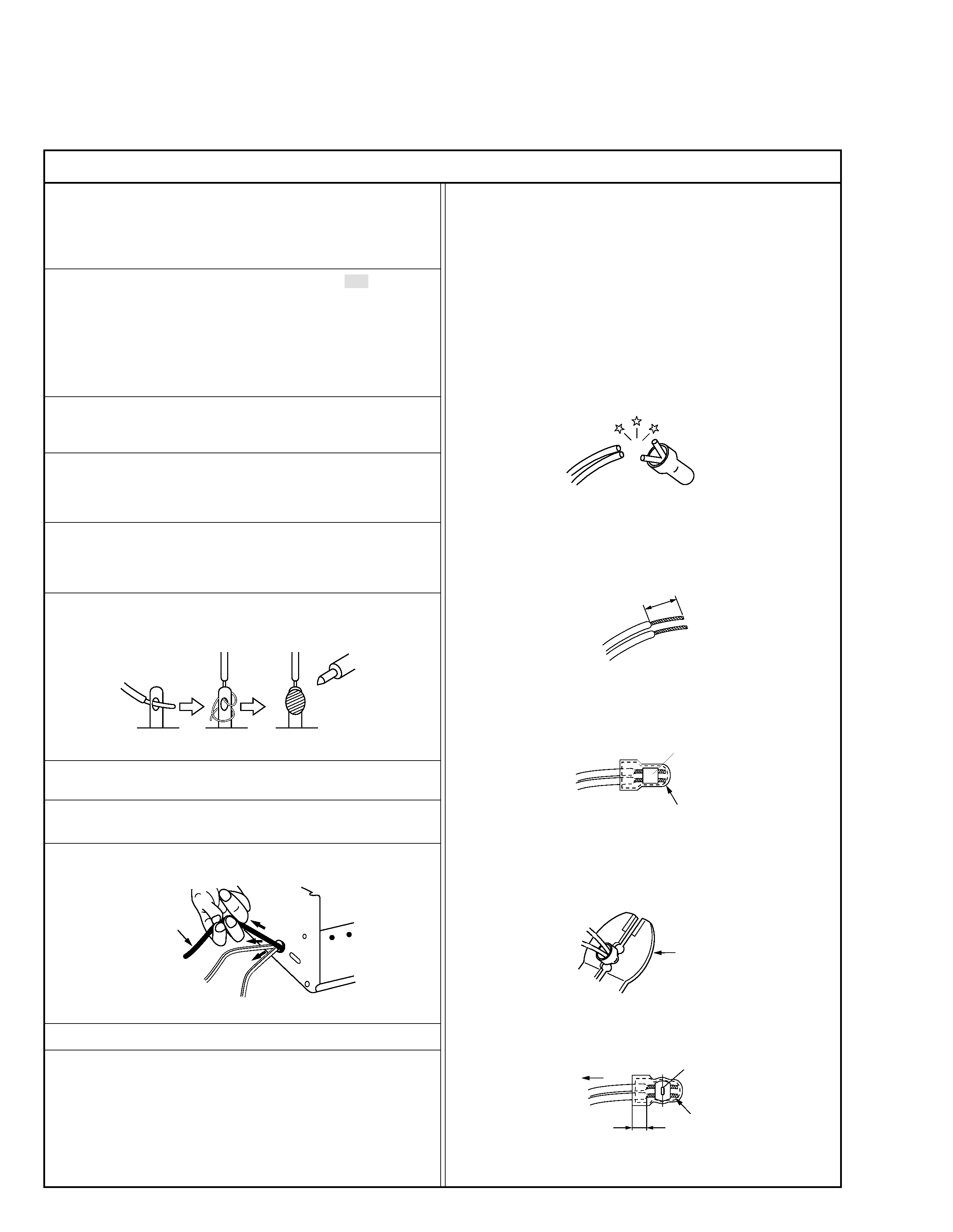
6. When replacing AC primary side components (transformers, power
cords, noise blocking capacitors, etc.) wrap ends of wires securely
about the terminals before soldering.
Power cord
Fig.2
10. Also check areas surrounding repaired locations.
11. Products using cathode ray tubes (CRTs)
In regard to such products, the cathode ray tubes themselves, the
high voltage circuits, and related circuits are specified for compli-
ance with recognized codes pertaining to X-ray emission.
Consequently, when servicing these products, replace the cath-
ode ray tubes and other parts with only the specified parts. Under
no circumstances attempt to modify these circuits.
Unauthorized modification can increase the high voltage value and
cause X-ray emission from the cathode ray tube.
12. Crimp type wire connector
In such cases as when replacing the power transformer in sets
where the connections between the power cord and power trans-
former primary lead wires are performed using crimp type connec-
tors, if replacing the connectors is unavoidable, in order to prevent
safety hazards, perform carefully and precisely according to the
following steps.
1) Connector part number : E03830-001
2) Required tool : Connector crimping tool of the proper type which
will not damage insulated parts.
3) Replacement procedure
(1) Remove the old connector by cutting the wires at a point
close to the connector.
Important : Do not reuse a connector (discard it).
Fig.7
cut close to connector
Fig.3
(2) Strip about 15 mm of the insulation from the ends of the
wires. If the wires are stranded, twist the strands to avoid
frayed conductors.
15 mm
Fig.4
(3) Align the lengths of the wires to be connected. Insert the
wires fully into the connector.
Connector
Metal sleeve
Fig.5
(4) As shown in Fig.6, use the crimping tool to crimp the metal
sleeve at the center position. Be sure to crimp fully to the
complete closure of the tool.
I
·Precautions during Servicing
7. Observe that wires do not contact heat producing parts (heatsinks,
oxide metal film resistors, fusible resistors, etc.)
8. Check that replaced wires do not contact sharp edged or pointed
parts.
9. When a power cord has been replaced, check that 10-15 kg of
force in any direction will not loosen it.
1.2
5
2.0
5.5
Crimping tool
Fig.6
(5) Check the four points noted in Fig.7.
Not easily pulled free
Crimped at approx. center
of metal sleeve
Conductors extended
Wire insulation recessed
more than 4 mm
S40888-01