HM-DR10000EU
3
4
4
30 SEC
MTP
PAL
POWER
TIMER
REC LINK DIGITAL TBC/NR
STD
LS3
1
. , ?
ABC
DEF
GHI
JKL
MNO
PQRS
TUV
WXYZ
2
3
4
5
6
7
8
9
1
2
1
2
3
VCR
TV
CABLE
/SAT
TV/VCR
:
AUDIO
0000
START
DEBUT
STOP
FIN
DATE
TV
PROG
DAILY/QTDN.
VPS/PDC
AUX
WEEKLY/HEBDO
EXPRESS
LCD PROG
ENTER/ENTREE
0
PROG
NAVIGATION
OK
3
4
4
MENU
30 SEC
TV PROG +
TV PROG
T
V
TV
+
EN
CONTENTS
SAFETY FIRST
2
Safety Precautions ................................... 2
INSTALLING YOUR NEW RECORDER
4
Basic Connection .................................... 4
S-VIDEO Connection .............................. 5
INITIAL SETTINGS
6
Auto Set Up ............................................ 6
Preset Download ..................................... 8
Language .............................................. 10
On-Screen Displays ............................... 11
Power Save Mode ................................. 12
T-V LINK
13
T-V Link Functions ................................ 13
INFORMATION ON COLOUR SYSTEM
14
Colour System Set ................................. 14
PLAYBACK
15
Basic Playback ...................................... 15
Playback Features ................................. 16
RECORDING
22
Basic Recording .................................... 22
Recording Features ................................ 24
B.E.S.T. Picture System .......................... 28
TIMER RECORDING
30
SHOWVIEW® Timer Programming ............. 30
Express Timer Programming .................. 32
Automatic Satellite
Programme Recording ........................... 37
VIDEO NAVIGATION
38
Navigation ............................................ 38
Title Editing ........................................... 40
SPECIAL FEATURES
46
Remote Control Functions ..................... 46
EDITING
49
Preparation For Editing .......................... 49
Edit From A Camcorder ......................... 50
Edit To Or From Another Video
Recorder ............................................... 52
Synchro Editing ..................................... 55
INFORMATION ON J TERMINAL
56
SYSTEM CONNECTIONS
57
Connection To A Satellite Tuner ............. 57
Connecting/Using A Decoder ................ 60
Connecting/Using A Stereo System ........ 61
SUBSIDIARY SETTINGS
62
Tuner Set ............................................... 62
SHOWVIEW® Setup ................................... 69
Clock Set ............................................... 70
TROUBLESHOOTING
72
QUESTIONS AND ANSWERS
75
INDEX
76
SPECIFICATIONS
82
LIST OF TERMS
83
ENGLISH
D-VHS DIGITAL RECORDER
INSTRUCTIONS
LPT0300-001B
FIRST
SEE
AUTO SET-UP
ON BACK
2 EN
For Italy:
"It is declared that this product, brand JVC, conforms to
the Ministry Decree n. 548 of 28 Aug.'95 published in
the Official Gazette of the Italian Republic n. 301 of 28
Dec.'95"
SAFETY FIRST
IMPORTANT
Please read the various precautions on page 2 and
3 before installing or operating the recorder.
It should be noted that it may be unlawful to re-
record pre-recorded tapes, records, or discs
without the consent of the owner of copyright in
the sound or video recording, broadcast or cable
programme and in any literary, dramatic, musical,
or artistic work embodied therein.
Safety Precautions
Cassettes marked "D-VHS", "S-VHS" and "VHS" can be used
with this video cassette recorder. However, D-VHS recordings
are possible only with cassettes marked "D-VHS".
D-VHS is a new digital memory system that uses D-VHS
tapes. D-VHS was developed as a memory system for
multimedia applications that require storage for large
volumes of information, such as for digital video.
SHOWVIEW is a registered trademark of Gemstar Development
Corporation. The SHOWVIEW system is manufactured under
licence from Gemstar Development Corporation.
CAUTION
When you are not using the recorder for a long
period of time, it is recommended that you
disconnect the power cord from the mains outlet.
Dangerous voltage inside. Refer internal servicing
to qualified service personnel. To prevent electric
shock or fire hazard, remove the power cord from
the mains outlet prior to connecting or discon-
necting any signal lead or aerial.
WARNING
There are two different types of SECAM colour
systems: SECAM-L, used in FRANCE (also called
SECAM-West), and SECAM-B, used in Eastern
European countries (also called SECAM-East).
1. This recorder can also receive SECAM-B colour
television signals for recording and playback.
2. Recordings made of SECAM-B television signals
produce monochrome pictures if played back on
a video recorder of SECAM-L standard, or do not
produce normal colour pictures if played back on
a PAL video recorder with SECAM-B system
incorporated (even if the TV set is SECAM-
compatible).
3. SECAM-L prerecorded cassettes or recordings
made with a SECAM-L video recorder produce
monochrome pictures when played back with this
recorder.
4. This recorder cannot be used for the SECAM-L
standard. Use a SECAM-L recorder to record
SECAM-L signals.
The rating plate and the safety caution are on the rear of the unit.
WARNING: DANGEROUS VOLTAGE INSIDE
WARNING: TO PREVENT FIRE OR SHOCK HAZARD, DO NOT EXPOSE THIS UNIT TO RAIN OR
MOISTURE.
MTP
PAL
CAUTION
To avoid electric shock or damage to the unit, first
firmly insert the small end of the mains power
cord into the recorder until it is no longer wobbly,
and then plug the larger end of the mains power
cord into a mains outlet.
When you are not using the recorder for a long
period of time, it is recommended that you
disconnect the power cord from the mains outlet.
Dangerous voltage inside. Refer internal servicing
to qualified service personnel. To prevent electric
shock or fire hazard, remove the power cord from
the mains outlet prior to connecting or disconnect-
ing any signal lead or aerial.
EN
3
Failure to heed the following precautions may result in damage to the recorder, remote control or video
cassette.
1. DO NOT place the recorder . . .
... in an environment prone to extreme temperatures or humidity.
... in direct sunlight.
... in a dusty environment.
... in an environment where strong magnetic fields are generated.
... on a surface that is unstable or subject to vibration.
2. DO NOT block the recorder's ventilation openings.
3. DO NOT place heavy objects on the recorder or remote control.
4. DO NOT place anything which might spill on top of the recorder or remote control.
5. AVOID violent shocks to the recorder during transport.
MOISTURE CONDENSATION
Moisture in the air will condense on the recorder when you move it from a cold place to a warm place, or under
extremely humid conditions--just as water droplets form in the surface of a glass filled with cold liquid. Moisture
condensation on the head drum will cause damage to the tape. In conditions where condensation may occur, keep the
recorder turned on for a few hours to let the moisture dry.
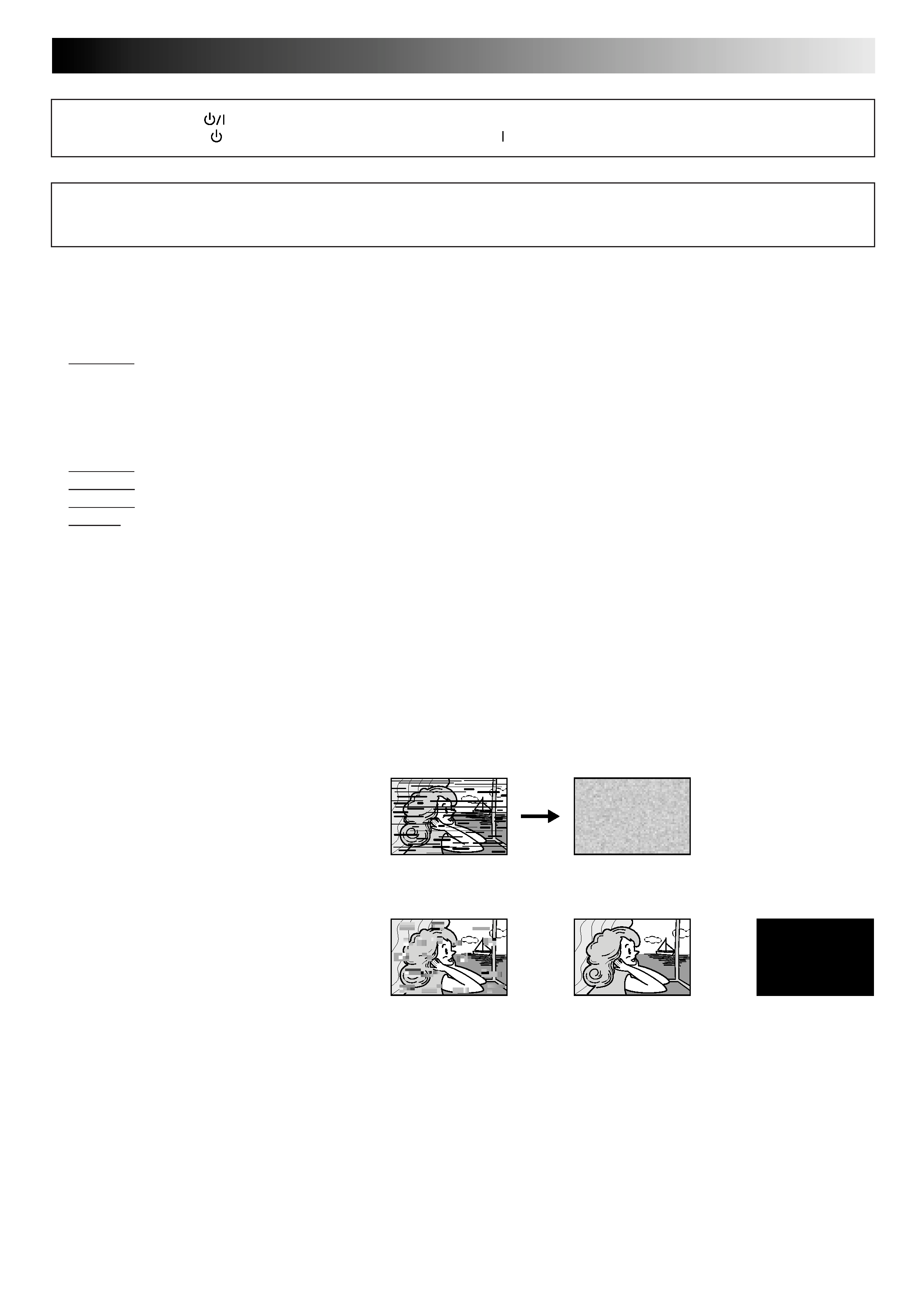
ABOUT HEAD CLEANING
After an extended period of use, the video heads can become dirty, resulting in a loss of picture or sound during
playback. If this happens, clean the video heads by using the optional cleaning tapes.
Symptoms of dirty video heads:
The picture is not clear, or does not appear.
There is no sound.
Mosaic (block) noise appears in the picture.
Black or mosaic horizontal stripes appear in the
picture.
The picture stops (as if the tape is paused).
A blank black or blue screen appears.
The picture is fuzzy. (VHS playback)
Use a cleaning tape designed specifically for D-VHS video heads (JVC D-VHS video head cleaner DFC-2) to clean the video heads.
In order to avoid misoperation, set "NAVIGATION" to "OFF" (
pg. 39).
Follow the instructions that are provided with the cleaning tape.
If you still do not get a clear picture after using a cleaning tape:
The heads may be worn. Contact your nearest JVC dealer.
During VHS playback, if there is a tracking problem, the picture may appear fuzzy. Adjust the tracking manually (
pg. 17).
The STANDBY/ON
button does not completely shut off mains power from the unit, but switches operating
current on and off. "
" shows electrical power standby and " " shows ON.
Video tapes recorded with this video recorder in the LP (Long Play) mode cannot be played back on a single-
speed video recorder.
VHS playback
Early symptom
Late symptom
D-VHS playback
Block noise
Still image
Black screen
4 EN
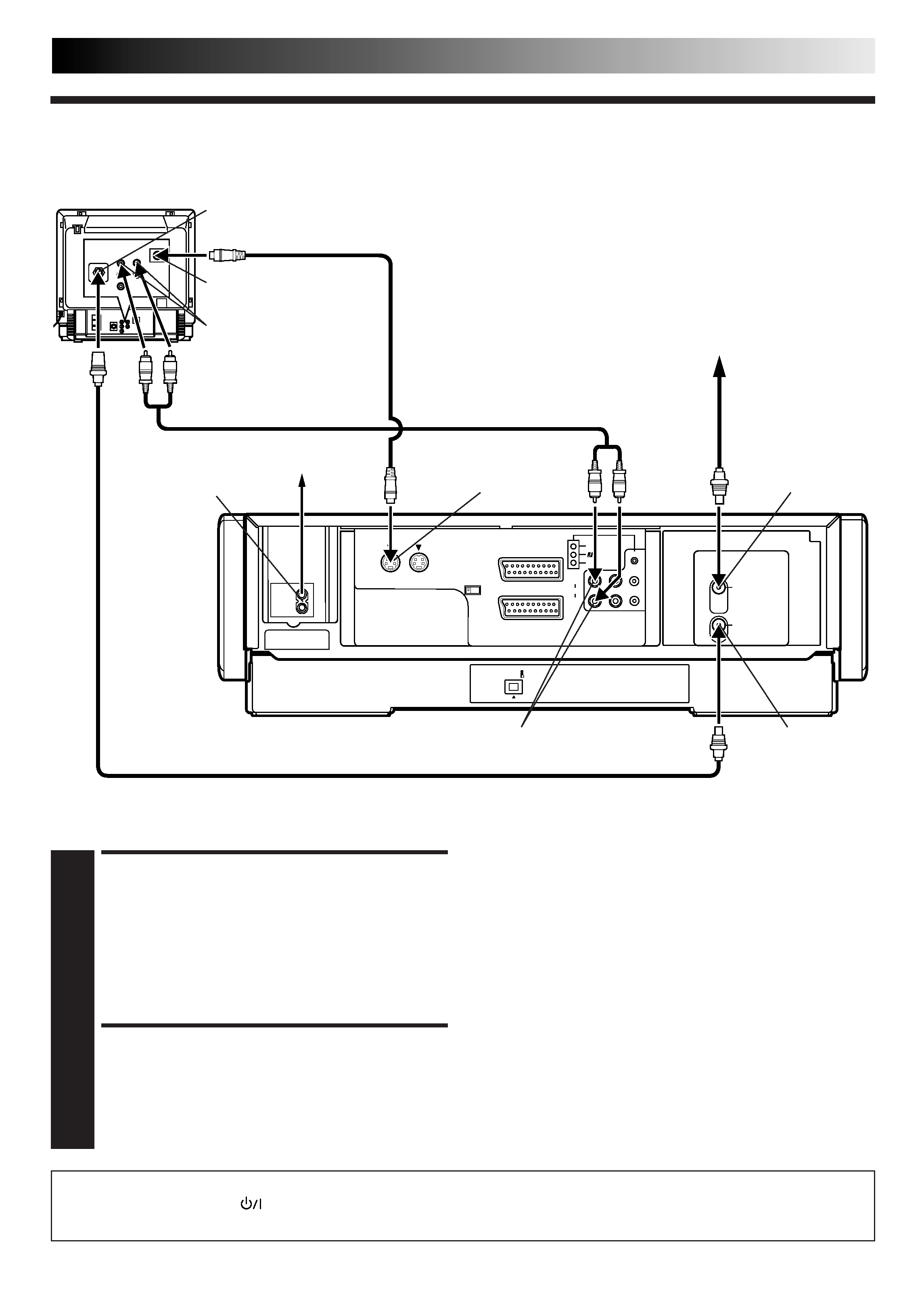
Basic
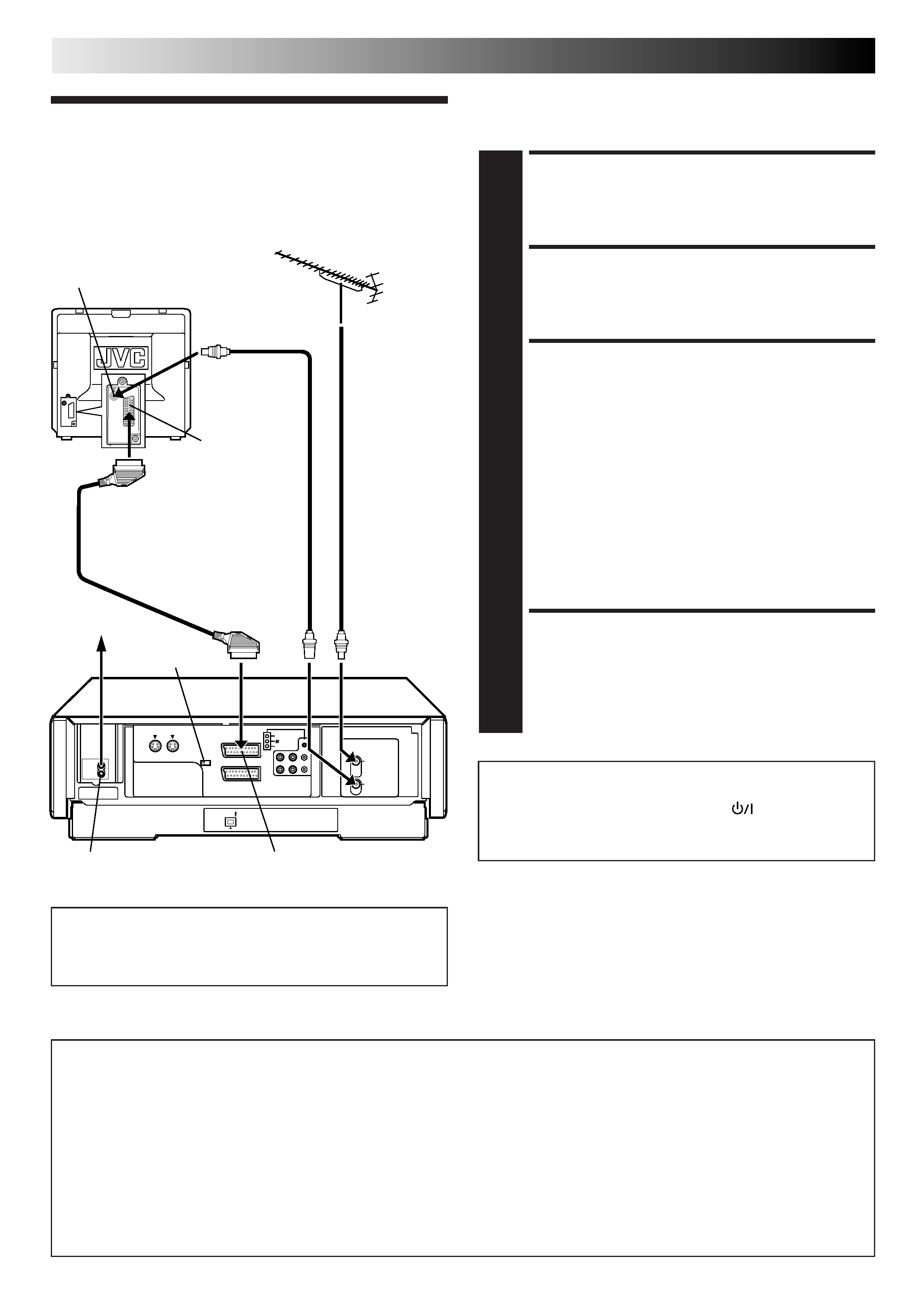
Connection
INSTALLING YOUR NEW RECORDER
21-pin SCART Cable
(provided)
21-pin SCART
connector
Back of TV
Mains power inlet
Aerial terminal
Rear view
Mains outlet
AV1 IN/OUT
RF Cable
(provided)
TV Aerial
Cable
AV1 INPUT/OUTPUT SIGNAL SELECTION FOR AV CONNECTION
The AV1 IN/OUT connector accepts and delivers either a composite signal (regular video signal) or a Y/C signal (a signal in
which the luminance and chrominance signals are separated). For input signal selection, select "VIDEO" (regular video signal) or
"S-VIDEO" (Y/C signal) for "AV1 SELECT" setting (
pg. 54). For output signal selection, use AV1 OUT switch of the rear panel.
If your TV's 21-pin AV input connector (SCART) is compatible only with the regular video signal, set this switch to COMP.
If your TV's 21-pin AV input connector (SCART) is compatible with the Y/C signal, set this switch to Y/C. You can obtain high-
quality S-VHS pictures. (For connection, be sure to use a 21-pin SCART cable that is compatible with the Y/C signal.)
NOTES:
Set your TV to the VIDEO (or AV), Y/C, or RGB mode according to the type of your TV's SCART connector.
For switching the TV's mode, refer to the instruction manual of your television.
To obtain high-quality S-VHS pictures, you can also use the S-VIDEO CONNECTION described on page 5.
AV1 OUT switch
CHECK CONTENTS
1 Makesurethepackagecontainsalloftheaccessories
listed in "Specifications" (
pg. 82).
SITUATE RECORDER
2 Placetherecorderonastable,horizontalsurface.
CONNECT RECORDER TO
TV
3 aDisconnecttheTVaerialcablefromtheTV.
b Connect the TV aerial cable to the ANT. IN jack on
the rear panel of the recorder.
c Connect the provided RF cable between the ANT.
OUT jack on the rear panel of the recorder and the
TV's aerial terminal.
d Connect the provided SCART cable between the
AV1 IN/OUT socket on the rear panel of the
recorder and the TV's 21-pin SCART connector.
e Set the AV1 OUT switch to the appropriate position.
See "AV1 INPUT/OUTPUT SIGNAL SELECTION FOR
AV CONNECTION" below.
CONNECT RECORDER TO
MAINS
4 Connecttheprovidedmainspowercordbetweenthe
mains power inlet on the rear panel of the recorder and
a mains outlet.
It's essential that your video recorder be properly connected.
Follow these steps carefully. THESE STEPS MUST BE COMPLETED
BEFORE ANY VIDEO OPERATION CAN BE PERFORMED.
After you plug the mains power cord into a mains outlet, the
Country Set display appears on the TV screen and/or on the
recorder's front display panel when the
button on the
recorder/remote control is pressed for the first time to power
on the recorder; go to page 6 to perform Auto Set Up.
ATTENTION:
Your TV must have a 21-pin AV input connector (SCART) for
the connection to the recorder.
EN
5
AV1 IN/OUT(L-1)
AV2 IN/DECODER(L-2)
DV IN
AV1 OUT
COMP. Y/C
S IN
(S-1)
S OUT
R.PAUSE
ANT. IN
ANT. OUT
R
L
AUDIO
OUT
IN(S-1)
SYNCHRO EDIT
JLIP
After you plug the mains power cord into a mains outlet, the Country Set display appears on the TV screen and/or on the recorder's
front display panel when the
button on the recorder/remote control is pressed for the first time to power on the recorder; go to
page 6 to perform Auto Set Up.
CONNECT RECORDER TO
TV
1 aConnecttheaerial,recorderandTVasper"Basic
Connection" (
pg. 4).
b Connect the recorder's S OUT connector to the TV's
S-VIDEO IN connector.
c Connect the recorder's AUDIO OUT connectors to
the TV's AUDIO IN connectors.
CONNECT RECORDER TO
MAINS
2 Connecttheprovidedmainspowercordbetweenthe
mains power inlet on the rear panel of the recorder and
a mains outlet.
To Connect to A TV With S-VIDEO/AUDIO IN Connectors . . .
S-VIDEO Connection
Mains outlet
Mains power inlet
AUDIO OUT
ANT. IN
Back of Recorder
ANT. OUT
Aerial or Cable
RF Cable (provided)
Back of TV
S-Video cable
(provided)
Audio cable (not provided)
S OUT
NOTES:
You can obtain high-quality S-VHS pictures.
If your television is not stereo-capable, use the recorder's
AUDIO OUT connectors to connect to an audio amplifier for
Hi-Fi stereo sound reproduction. (
pg. 61)
To operate the recorder with your TV using the S-VIDEO
connection, set your TV to the AV mode.
For switching the TV's mode, refer to the instruction manual
of your television.
AUDIO IN connectors
S-VIDEO IN connector
Aerial terminal