VICTOR COMPANY OF JAPAN, LIMITED
VIDEO DIVISION
Printed in Japan
S40894
COMPACT VHS CAMCORDER
GR-FXM37EG, SXM607EG/EK
No. 86589
November 2000
This service manual is printed on 100% recycled paper.
COPYRIGHT
© 2000 VICTOR COMPANY OF JAPAN, LTD.
SPECIFICATIONS (The specifications shown pertain specifically to the model GR-SXM607EG/FXM37EG)
GR-FXM37EG,
SXM607EG/EK
No.
86589
VHS
PAL
625
Audio
: 300 mV (rms), 1 k
analogue
output
(via Audio output connector)
S-Video
: Y : 1 V (p-p), 75
,
analogue output
C : 0.29 V (p-p), 75
,
analogue output
AC Adapter AP-V10EG
Power requirement
: AC 110 V to 240 V`,
50 Hz/60 Hz
Power consumption
: 23 W
Output
: DC 11 V
, 1 A
Dimensions
: 59 mm x 31 mm x 84 mm
(W x H x D)
Weight
: Approx. 140 g
Optional Accessories
· Battery Packs BN-V12U, BN-V20U, BN-V400U
· Compact S-VHS (
) Cassettes SE-C45/30
· Compact VHS (
) Cassettes EC-60/45/30
· Remote Control Unit RM-V700U
· Active Carrying Bag CB-V7U
· Cassette Adapter C-P7U
Viewfinder
: Electronic viewfinder with 0.5"
black/white CRT
White balance
adjustment
: Auto/Manual adjustment
LCD monitor
: 3" diagonally measured,
LCD panel/TFT active matrix
system (GR-SXM607)
: 2.5" diagonally measured, LCD
panel/TFT active matrix system
(GR-FXM37)
Speaker
: Monaural
Connectors
JLIP/EDIT
: ø3.5 mm, 4-pole, mini-head
jack (compatible with
RC-5325 plug)
Video
: 1 V (p-p), 75
unbalanced,
analogue output
(via Video output connector)
Camcorder
General
Format
: S-VHS (GR-SXM607)
VHS PAL standard
Power source
: DC 11 V
(Using AC Adapter)
DC 6 V
(Using battery pack)
Power consumption
LCD monitor* off,
viewfinder on
: 4.0 W
LCD monitor* on,
viewfinder off
: 4.5 W
Video light**
: 3.0 W
* Models equipped with LCD monitor only.
** GR-SXM607 only.
Signal system
: PAL-type
Video recording system
Luminance
: FM recording
Colour
: Converted sub-carrier
direct recording
Conforms to VHS standard
Cassette
:
/
cassette
Tape speed
SP
: 23.39 mm/sec.
LP
: 11.70 mm/sec.
Recording time (max.)
SP
: 60 minutes
LP
: 120 minutes
(with EC-60 cassette)
Operating
temperature
:0
°C to 40°C
Some accessories are not available in some areas. Please
consult your nearest JVC dealer for details on accessories
and their availability.
(models equipped with
LCD monitor only)
(models equipped with
LCD monitor only)
Specifications shown are for SP mode unless otherwise
indicated. E & O.E. Design and specifications subject to
change without notice.
Operating humidity
: 35% to 80%
Storage temperature
: 20
°C to 50°C
Weight
: Approx. 910 g (GR-SXM607)
Approx. 900 g (GR-FXM37)
Dimensions
: 200 mm x 112 mm x 118 mm
(W x H x D)
* Models equipped with LCD monitor only.
Pickup
: 1/4" format CCD
Lens
: F1.6, f = 3.9 mm to 62.4 mm,
16:1 power zoom lens with
auto iris and macro control,
filter diameter 40.5 mm
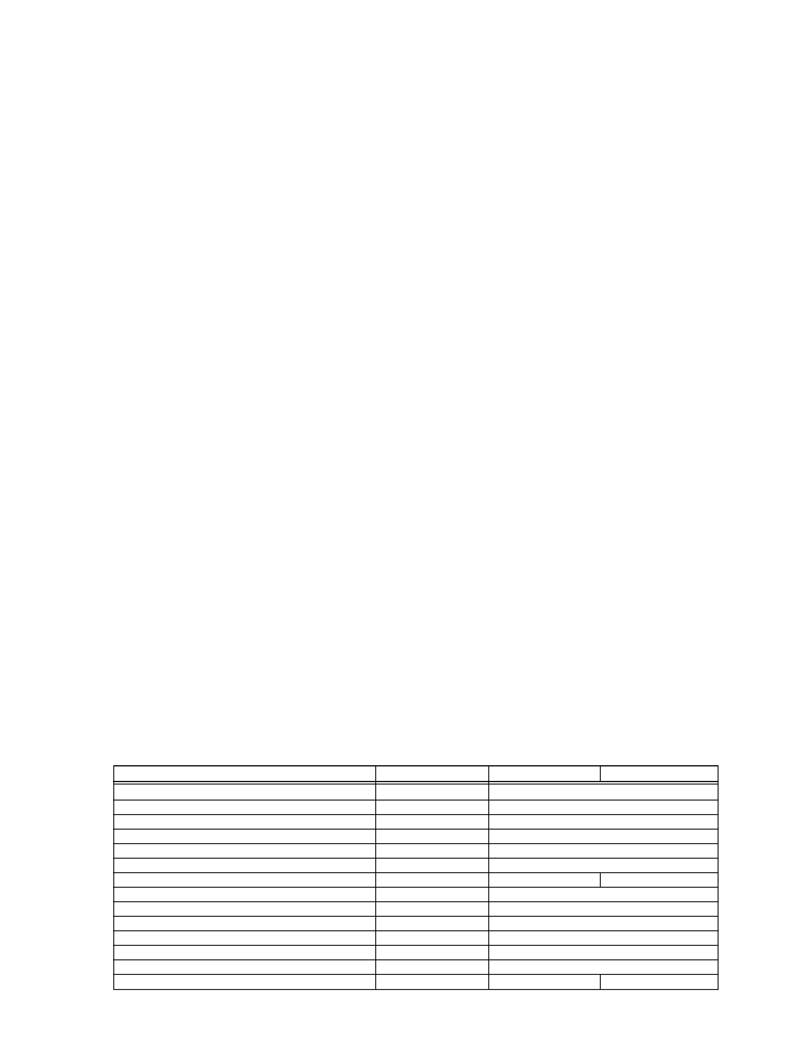
TABLE OF CONTENTS
Section
Title
Page
Important Safety Precautions
INSTRUCTIONS
1. DISASSEMBLY
1.1
SERVICE CAUTIONS .......................................................... 1-1
1.1.1
Precautions .................................................................. 1-1
1.1.2
How to read the disassembly and assembly ................ 1-1
1.1.3
Connection of the wires ................................................ 1-1
1.2
TOOLS REQUIRED FOR ADJUSTMENTS ......................... 1-2
1.3
DISASSEMBLY/ASSEMBLY OF CABINET PARTS ............. 1-3
1.3.1
Disassembly flow chart ................................................. 1-3
1.3.2
Disassembly method .................................................... 1-4
1.4
DISASSEMBLY/ASSEMBLY OF CAMERA SECTION
AND DECK SECTION ........................................................ 1-10
1.4.1
Flowchart of disassembly ........................................... 1-10
1.4.2
Disassembly method .................................................. 1-10
1.5
REPLACEMENT OF CCD IMAGE SENSOR ..................... 1-12
1.5.1
Removal of CCD image sensor .................................. 1-12
1.5.2
Installation of new CCD image sensor ....................... 1-12
1.5.3
Replacement of CCD board assy ............................... 1-12
1.6
TAKE OUT CASSETTE TAPE ............................................ 1-13
1.7
EMERGENCY DISPLAY ..................................................... 1-14
1.8
DEMONSTRATION MODE ................................................ 1-14
2. MECHANISM ADJUSTMENT
2.1
SERVICE CAUTIONS ............................................................ 2-1
2.1.1
Precautions .................................................................... 2-1
2.1.2
How to read the disassembly and assembly
(For Mechanism Parts) .................................................. 2-1
2.1.3
Required adjustment tools ............................................. 2-1
2.2
DISASSEMBLY/ASSEMBLY OF MECHANISM PARTS ........ 2-2
2.3
CHECKUP AND ADJUSTMENT OF MECHANISM
PHASE ................................................................................. 2-6
2.4
TAPE TRANSPORT ADJUSTMENT .................................... 2-7
2.4.1
Back tension ................................................................. 2-7
2.4.2
Tape pattern ................................................................. 2-7
2.4.3
A/CTL head height & azimuth ...................................... 2-8
2.4.4
Phase of control head (X value) ................................... 2-9
2.5
REMARKS ............................................................................ 2-9
2.5.1
Cleaning ....................................................................... 2-9
2.5.2
Applying oil and grease ................................................ 2-9
2.5.3
Checkup ....................................................................... 2-9
2.6
JIG CONNECTOR CABLE CONNECTION ........................ 2-10
3. ELECTRICAL ADJUSTMENT
3.1
ELECTRICAL ADJUSTMENT ............................................... 3-1
3.1.1
PREPARATION ............................................................ 3-1
3.2
MONITOR ADJUSTMENT .................................................... 3-3
3.2.1
V COM .......................................................................... 3-3
3.3
ELECTRONIC VIEWFINDER (E. VF) ADJUSTMENT ......... 3-4
3.3.1
Horizontal sync. ............................................................ 3-4
3.3.2
PLL adjustment ............................................................ 3-4
3.3.3
Centering ...................................................................... 3-4
3.3.4
Focus ............................................................................ 3-5
3.3.5
Brightness .................................................................... 3-5
3.4
SERVICE NOTE ................................................................... 3-6
4. CHARTS AND DIAGRAMS
NOTES OF SCHEMATIC DIAGRAM ................................... 4-1
CIRCUIT BOARD NOTES .................................................... 4-2
4.1
BOARD INTERCONNECTIONS .......................................... 4-3
4.2
CPU SCHEMATIC DIAGRAM .............................................. 4-5
4.3
VTR ASP SCHEMATIC DIAGRAMS .................................... 4-7
4.4
MECHA MDA SCHEMATIC DIAGRAM ................................ 4-9
4.5
VTR DSP SCHEMATIC DIAGRAM .................................... 4-11
4.6
DSP SCHEMATIC DIAGRAM ............................................. 4-13
4.7
IRIS & AF/ZOOM SCHEMATIC DIAGRAMS ...................... 4-15
4.8
VIDEO OUT SCHEMATIC DIAGRAM ................................ 4-17
4.9
REGULATOR SCHEMATIC DIAGRAM .............................. 4-19
4.10 LCD CTL SCHEMATIC DIAGRAM ..................................... 4-21
4.11 JACK AND CCD SCHEMATIC DIAGRAMS ....................... 4-23
4.12 SPEAKER AND MONITOR
SCHEMATIC DIAGRAMS .................................................. 4-25
4.13 TOP OPE UNIT, ZOOM UNIT, REAR UNIT
AND SENSOR SCHEMATIC DIAGRAMS ........................... 4-27
4.14 ELECTRONIC VIEWFINDER SCHEMATIC DIAGRAM ......... 4-29
4.15 MAIN CIRCUIT BOARD ..................................................... 4-31
4.16 CCD CIRCUIT BOARD ...................................................... 4-37
4.17 MONITOR CIRCUIT BOARD ............................................. 4-39
4.18 ELECTRONIC VIEWFINDER CIRCUIT BOARD ............... 4-41
4.19 POWER SYSTEM BLOCK DIAGRAM ............................... 4-43
4.20 CAMERA BLOCK DIAGRAM ............................................. 4-45
4.21 Y/C BLOCK DIAGRAM ....................................................... 4-49
4.22 MONITOR BLOCK DIAGRAM ............................................ 4-51
4.23 CPU/MDA BLOCK DIAGRAM ............................................ 4-53
4.24 WAVEFORMS .................................................................... 4-55
4.25 VOLTAGE CHARTS ........................................................... 4-56
5. PARTS LIST
5.1
PACKING ASSEMBLY <M1> ................................................ 5-1
5.2
FINAL ASSEMBLY <M2> ..................................................... 5-3
5.3
MECHANISM ASSEMBLY <M3> ......................................... 5-6
5.4
ELECTRONIC VIEWFINDER ASSEMBLY <M4> ................. 5-8
5.5
MONITOR ASSEMBLY <M5> ............................................... 5-9
5.6
ELECTRICAL PARTS LIST ................................................ 5-10
MAIN BOARD ASSEMBLY <01> ........................................ 5-10
CCD BOARD ASSEMBLY <02> ......................................... 5-17
MONITOR BOARD ASSEMBLY <07> ................................ 5-17
E. VF BOARD ASSEMBLY <50> ........................................ 5-18
Section
Title
Page
GR-FXM37EG
GR-SXM607EG
GR-SXM607EK
VIDEO LIGHT
NOT USED
USED
IR RECEIVER
NOT USED
USED
LCD MONITOR
2.5"
3"
BODY COLOR
Mold Black
Silver
IMAGE SENSOR
1/4" 320K
1/4" 470K
HORIZONTAL RESOLUTION
300LINES
400LINES
AC CORD
CEE TYPE
CEE TYPE
UK TYPE
BATTERY PACK
BN-BV11U
BN-20BU
RCU UNIT
NOT USED
PROVIDE
SNAP SHOT
NOT USED
USED (FULL ONLY)
NIGHT SCOPE
NOT USED
USED
5 SEC REC SW
USED
NOT USED
S-VHS ON/OFF
NOT USED
USED
VIDEO OUT SELECT PAL/SECAM
NOT USED
USED
NOT USED
The following table lists the differing points between Models GR-FXM37EG and GR-SXM607EG/EK in this series.
1-1
(1) Order of steps in Procedure
When reassembling, preform the step(s) in the reverse
order. These numbers are also used as the identifica-
tion (location) No. of parts Figures.
(2) Part to be removed or installed.
(3) Fig. No. showing Procedure or Part Location.
C = Cabinet
CA = Camera
D = Deck
(4) Identification of part to be removed, unhooked, unlocked,
released, unplugged, unclamped or unsoldered.
P = Spring
W = Washer
S = Screw
* = Unhook, unlock, release, unplug or unsolder.
2(S3) = 2 Screws (S3)
CN = Connector
(5) Adjustment information for installation.
1
CASSETTE
C1
2(S1)
COVER ASSEMBLY
2
UPPER CASE
C2
2(S2), (L2)
LOWER CASE
C3
9(S3), (L3a), (L3b)
3
ASSEMBLY(INCL.
*CN 3a 3b
E. VF. ASSEMBLY)
CAP (RCA jack)
SECTION 1
DISASSEMBLY
1.1 SERVICE CAUTIONS
1.1.1
Precautions
1. Before disassembling/re-assembling the set as well as
soldering parts, make sure to disconnect the power
cable.
2. When disconnecting/connecting connectors, pay enough
attention to wiring not to damage it.
3. In general, chip parts such as resistor, shorting jumpers
(0-ohm resistor), ceramic capacitors, diodes, etc. can not
be reused after they were once removed.
4. When installing parts, be careful not to do with other parts
as well as not to damage others.
5. When removing ICs, be careful not to damage circuit
patterns.
6. Tighten screws properly during the procedures. Unless
specified otherwise, tighten screws at torque of 0.196 N·m
(2.0 kgf·cm).
1.1.2
How to read the disassembly and assembly
STEP
/LOC
PART
NO.
REMOVAL
(For Cabinet Parts)
Fig.
No.
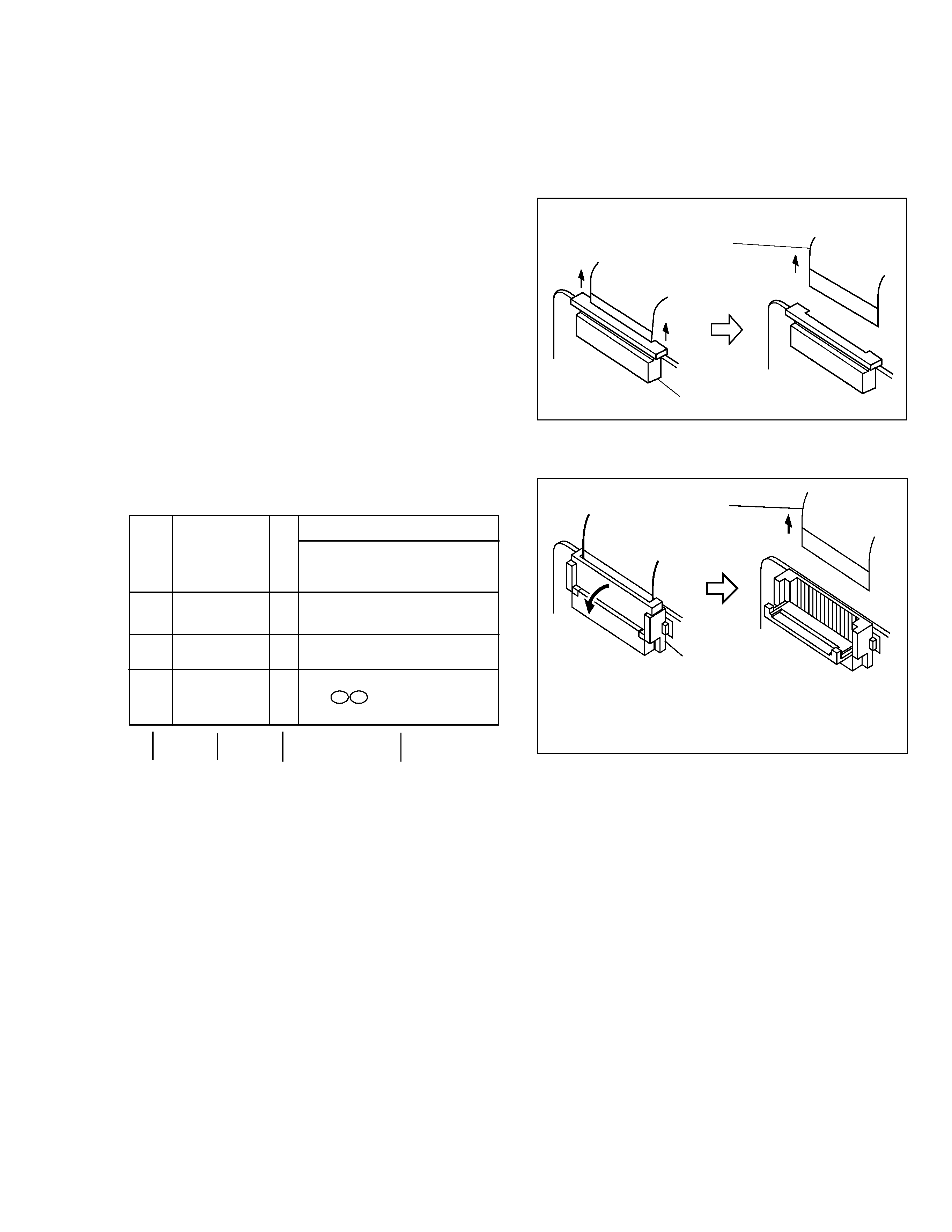
1.1.3
Connection of the wires
1. Pull the connector structure upward to release the clamp
when removing or inserting the flat wire cable.
Fig. 1-1-1
Connector
Wire
Connector
Wire
Fig. 1-1-2
NOTE:
After removing the wire, return the stopper to
its original position, because it is apt to come
off if it is left open.
*UNLOCK/RELEASE/
UNPLUG/UNCLAMP/
UNSOLDER
(1)
(2)
(3)
(4)
L
L
L
L
1-2
1
2
INF adjustment lens
YTU92001B
Torque driver
YTU94088
3
4
Bit
YTU94088-003
5
6
Alignment tape
(for SP interchangeability)
MHP-C
Alignment tape
(for N. SP PB Y/C level)
MHV-2C
INF lens holder
YTU94087
78
910
11
12
13
14
Camera stand
YTU93079
Conn. ring
YTU92001-111
Gray Scale Chart
YTU94133A
Color Bar Chart
YTU94133C
Light box Assembly
YTU93096A
Extension connector
YTU94145B-30
Service support system software
YTU94057-51
Cleaning cloth
KSMM-01
15
16
PC cable
QAM0099-002
Jig connector cable
YTU93106A
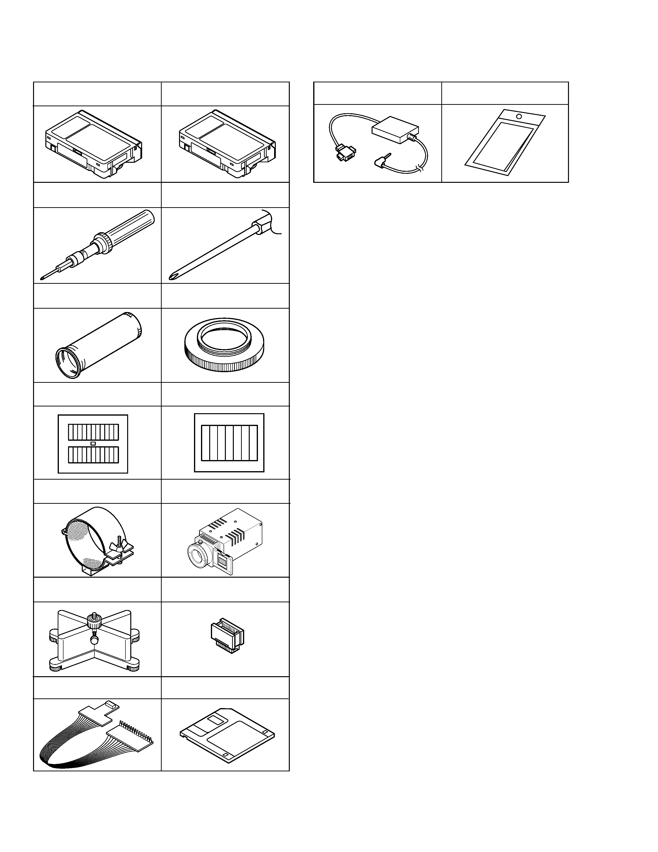
1.2 TOOLS REQUIRED FOR ADJUSTMENTS
Table 1-2-1
1-3
1,2. Alignment tape
To be used for check and adjustment of interchangeability
of the mechanism.
(Video: Color bar signal, Audio: Non-signal)
3. Torque driver
Be sure to use to fastening the mechanism and exterior
parts because those parts must strictly be controlled for
tightening torque.
4. Bit
This bit is slightly longer than those set in conventional
torque drivers.
5. INF adjustment lens
To be used for adjustment of the camera system.
6. Conn. ring
The connector ring to attach the INF. lens to the head of
the OP lens.
7. Color bar chart
To be used for adjustment of the camera system.
8. Gray scale chart
To be used for adjustment of the camera system.
9. INF lens holder
To be used together with the camera stand (11) for
operating the VideoMovie in the stripped-down condition
such as the status without the exterior parts or for using
commodities that are not yet conformable to the
interchangeable ring.
10. Light box
To be used for adjustment of the camera system.
11. Camera stand
To be used together with the INF adjustment lens holder.
12. Extention connector
To be used to JIG connector cable
13. JIG connector cable
Connected to CN25 of the main board and used for
measuring error rates, etc.
14. Service support software
To be used for adjustment with a personal computer.
15. PC cable
To be used to connect the VideoMovie and a personal
computer with each other when a personal computer is
used for adjustment.
16. Cleaning cloth
Recommended cleaning cloth to wipe down the video
heads, mechanism (tape transport system), optical lens
surface.
1.3 DISASSEMBLY/ASSEMBLY OF CABINET PARTS
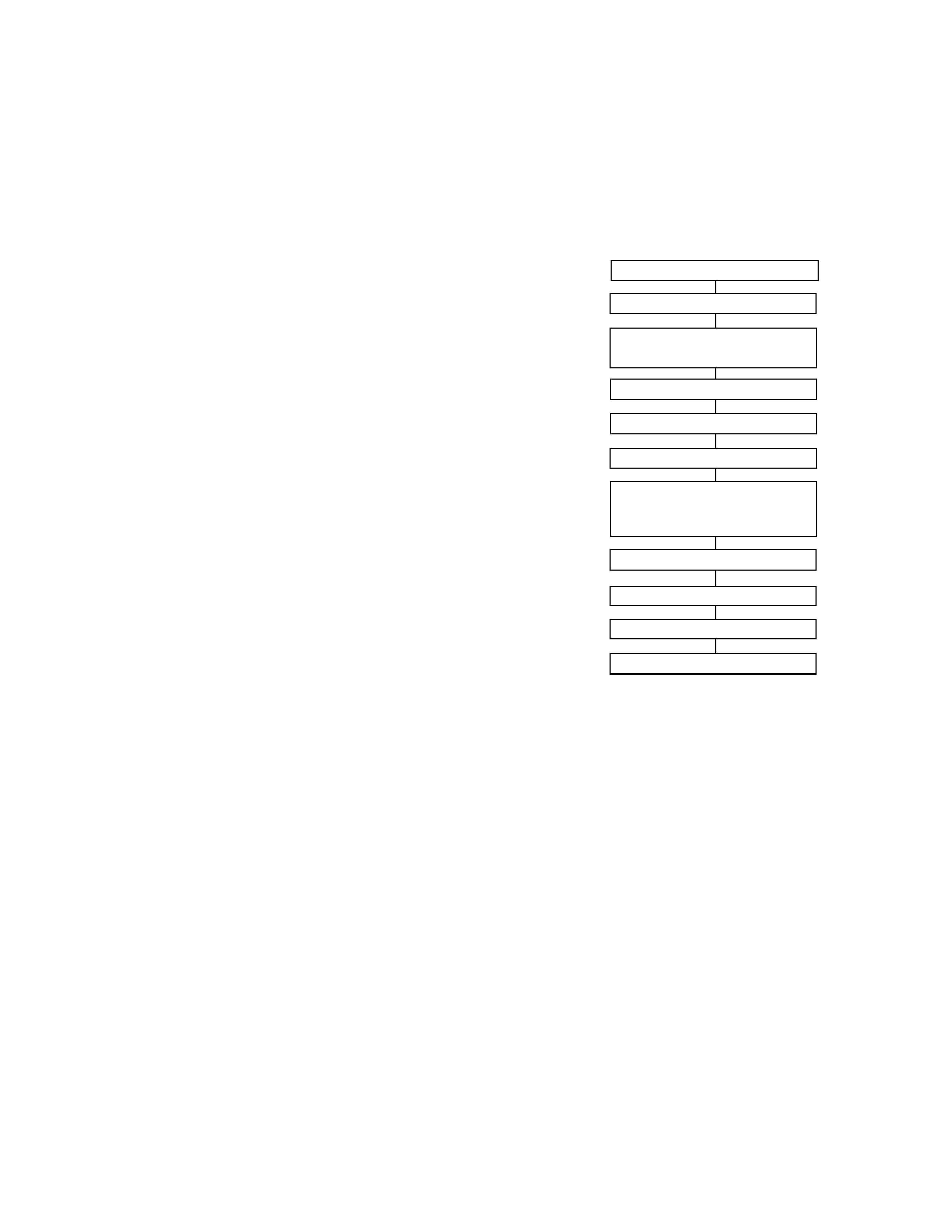
1.3.1
Disassembly flow chart
This flowchart indicates the disassembly step for the cabi-
net parts and board assembly in order to gain access to
item(s) to be serviced. When reassembling, perform the
step(s) in reverse order. Bend, route and dress the flat ca-
bles as they were originally.
M
M
M
M
M
M
M
M
M
M
M
1
Cassette cover assembly
2
Upper case
3
Lower case assembly
(Incl. E. VF assembly)
4
E. VF assembly
5
Top operation unit
6
Rear unit
7
Front cover assembly
(Incl. Microphone,
DC light assembly)
8
Microphone
9
DC light assembly
0
Monitor assembly
-
Front frame assembly
Note:
For screw management, refer to the table appearing
in the section "3.4 SERVICE NOTE" (page 3-6).