COMPACT VHS CAMCORDER
GR-AXM237UM
SPECIFICATIONS
No. 86544
February 2000
This service manual is made from all recycled paper.
COPYRIGHT
© 2000 VICTOR COMPANY OF JAPAN, LTD.
Regarding service information other than these sections, refer to the GR-AXM220U service manual (No. 86526).
Also, be sure to note important safety precautions provided in the service manual.
Power consumption : 23 W
Output
Charge
: DC 8.5 V
, 1.3 A
VTR
: DC 6.3 V
, 1.8 A
Charging system
: Constant current, peak
detection, timer controlled
Dimensions
: 125 mm x 42 mm x 68 mm
(W x H x D)
(4-15/16" x 1-11/16" x
2-11/16")
Weight
: Approx. 270 g (0.6 lbs)
Cassette Adapter C-P7U
Dimensions
: 188 mm x 25 mm x 104 mm
(W x H x D)
(7-7/16" x 1" x 4-1/8")
Weight
: Approx. 240 g (0.53 lbs)
Accessory
: "AA (R6)"-size battery x 1
Optional Accessories
·Battery Packs BN-V12U, BN-V20U, BN-V856U
·Car Battery Charger BH-V3U
·Battery Charger BH-VC10U
·Audio/Video Cable
·Car Battery Cord AP-V7U
·Compact VHS (
) Cassettes TC-40/30/20
·Active Carrying Bag CB-V7U
Camcorder
General
Format
: VHS NTSC standard
Power source
: DC 6.0 V
Power consumption
LCD monitor off,
viewfinder on
: 4.2 W
LCD monitor on,
viewfinder off
: 4.6 W
LCD monitor on,
viewfinder on
: 5.2 W
Signal system
: NTSC-type
Video recording system
Luminance
: FM recording
Color
: Converted sub-carrier
direct recording
Conforms to VHS standard
Cassette
:
cassette
Tape speed
SP
: 33.35 mm/sec. (1-5/16 ips)
EP
: 11.12 mm/sec. (7/16 ips)
Recording time (max.)
SP
: 40 minutes
EP
: 120 minutes (with TC-40)
Operating
temperature
:0
°C to 40°C (32°F to 104°F)
Operating humidity : 35% to 80%
Storage temperature : 20
°C to 50°C
(4
°F to 122°F)
Weight
: Approx. 890 g (2.0 lbs)
Specifications shown are for SP mode unless otherwise indicated. E & O.E. Design and specifications subject to change without notice.
Dimensions
: 198 mm x 119 mm x 99 mm
(W x H x D)
(7-13/16" x 4-11/16" x 3-15/
16") (with the LCD monitor
closed and with the view-
finder fully tilted downward)
Pickup
: 1/4" format CCD
Lens
: F1.6, f = 3.9 to 62.4 mm, 16:1
power zoom lens with auto
iris and macro control, filter
diameter 40.5 mm
Viewfinder
: Electronic viewfinder with
0.5" black/white CRT
White balance
adjustment
: Auto/Manual adjustment
LCD monitor
: 2.5" diagonally measured,
LCD panel/TFT active matrix
system
Speaker
: Monaural
JLIP
: ø3.5 mm, 4-pole, mini-head
jack (compatible with
RC-5325 plug)
Video
:1 V (p-p), 75
unbalanced,
analog output
(via Video output connector)
Audio
: 300 mV (rms), 1 k
analog
output (via Audio output
connector)
AC Power Adapter/Charger AA-V16U
Power requirement : AC 110 V to 240 V`,
50 Hz/60 Hz
Some accessories are not available in some areas.
Please consult your nearest JVC dealer for details
on accessories and their availability.
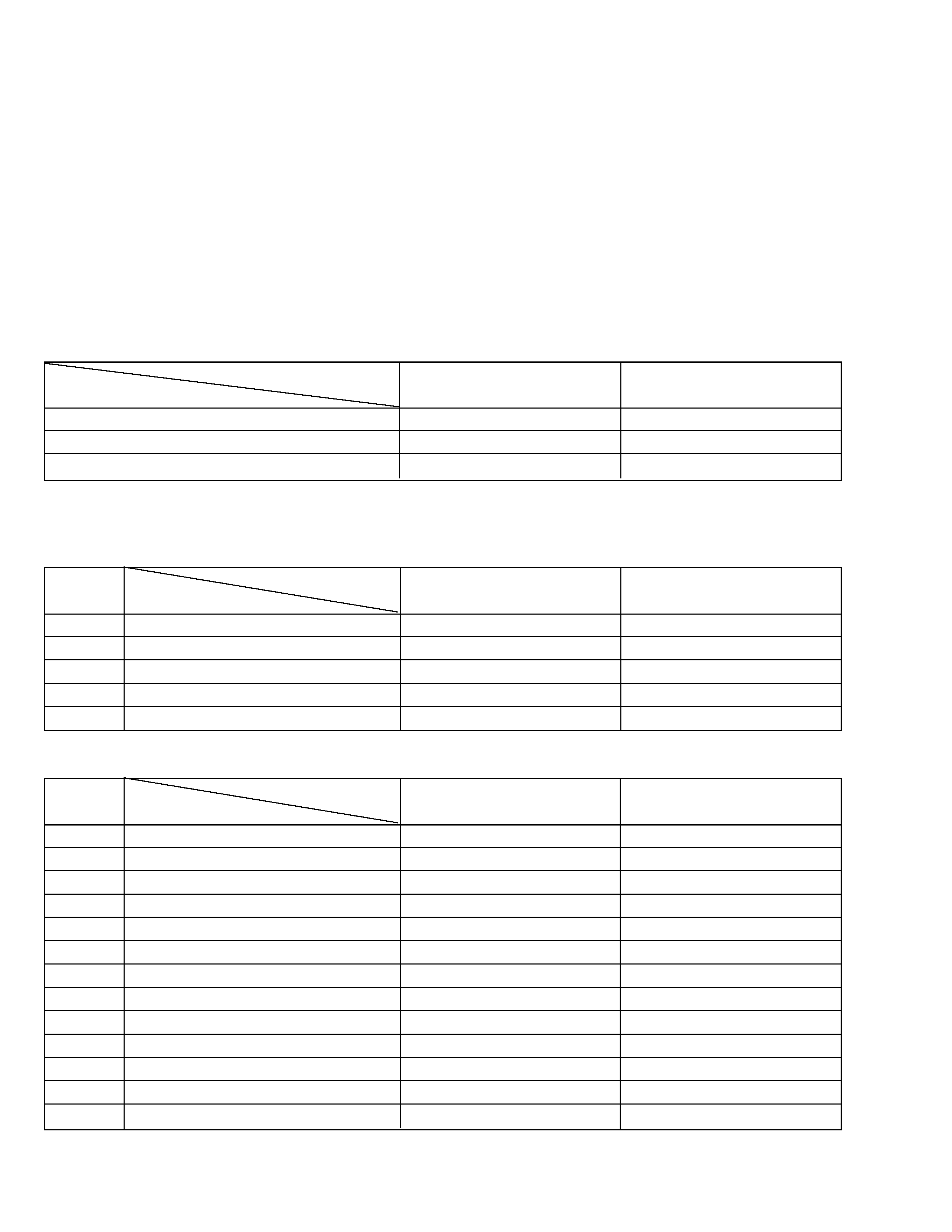
TABLE OF CONTENTS
DIFFERENT TABLE ................................................................................................................................................................ 1 to 2
4.
CHARTS AND DIAGRAMS
4.1
BOARD INTERCONNECTIONS ................................................................................................................................ 4-1
4.2
CPU SCHEMATIC DIAGRAM .................................................................................................................................... 4-3
4.3
VTR DSP SCHEMATIC DIAGRAM ............................................................................................................................ 4-5
4.4
REGULATOR SCHEMATIC DIAGRAM ..................................................................................................................... 4-7
4.5
MAIN CIRCUIT BOARD ............................................................................................................................................. 4-9
5.
PARTS LIST
5.1
FINAL ASSEMBLY <M2> ........................................................................................................................................... 5-1
DC LIGHT
Not used
used
BODY COLOR
Black
Pearl gray
ZOOM
300X
450X
The following table indicate main different points between models GR-AXM220U and GR-AXM237UM.
GR-AXM220U
GR-AXM237UM
MODEL
ITEM
The following table indicate different parts number between models GR-AXM220U and GR-AXM237UM.
PACKING ASSEMBLY<M1>
2
PACKING CASE
LY31561-007A
LY31561-028A
!
5
IB (EN)
LYT0478-001A
LYT0505-001A
!
IB (SP)
LYT0505-002A
!
IB (PT)
LYT0505-003A
7
REGIST. CARD
BT-51020-2
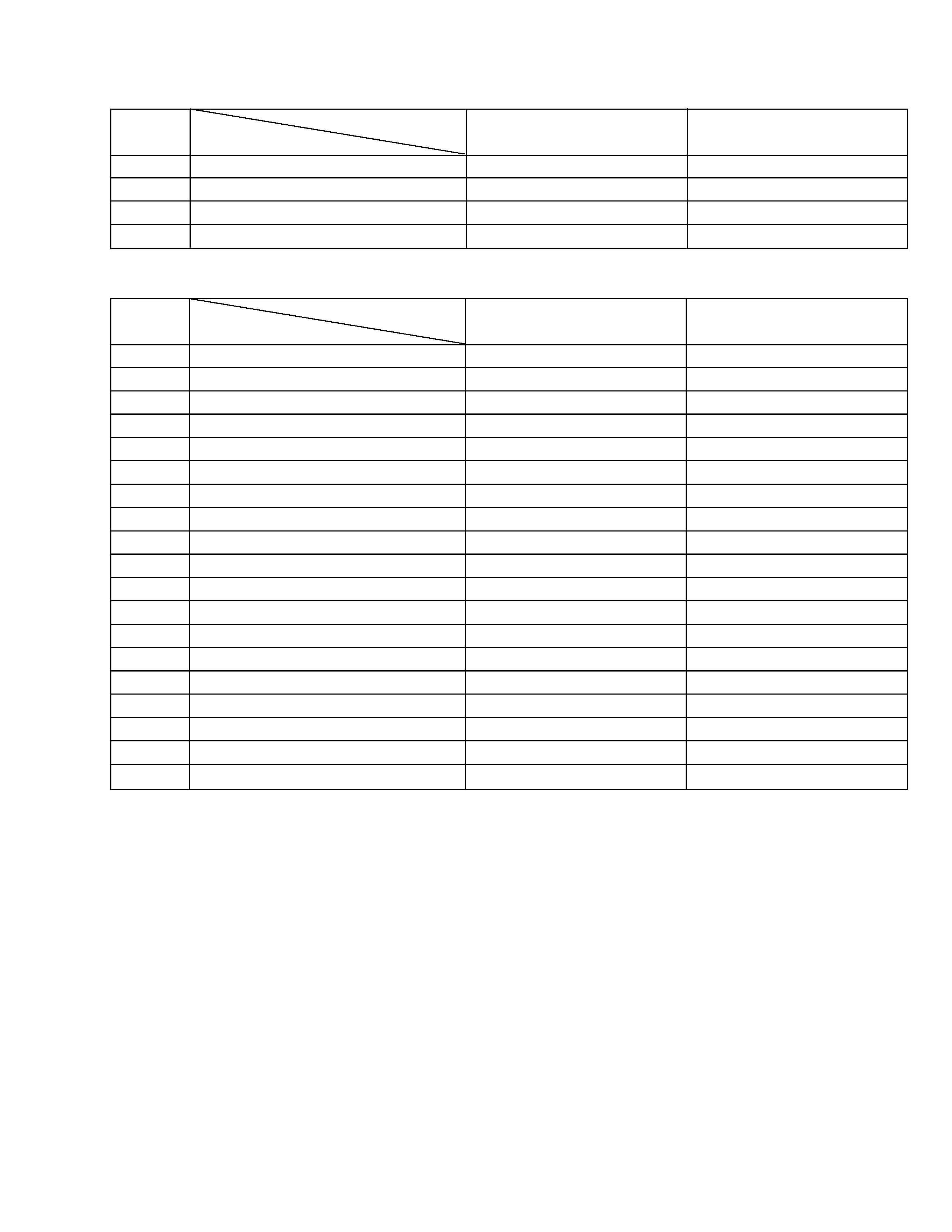
MODEL
ITEM
REF NO.
Note:
Mark is not used.
GR-AXM220U
GR-AXM237UM
! 101
LOWER CASE ASSY
LY10122-033A
LY10122-047A
106
FRONT COVER ASSY
LY10124-041A
LY10124-050B
106R
COVER (LIGHT)
LY30934-001A
107
CASS. COVER (M) ASSY
LY10131-019A
LY10131-023A
108
UPPER CASE (M)
LY10133-001C
LY10133-002C
110
TOP COVER
LY10129-074A
LY10129-093A
113
OPERATION UNIT
LY10120-035A
LY10120-032B
116
DC LIGHT ASSY
LY30860-001B
116A
LAMP
YQ44266
! 137
FRAME ASSY
LY20372-002B
LY20372-004A
137F
CONTACT (LIGHT), X2
YQ43810
137G
E-SI C WIRE C-F
WJM0118-001A
146
KNOB (LIGHT)
LY41083-001B
MODEL
ITEM
REF NO.
GR-AXM220U
GR-AXM237UM
FINAL ASSEMBLY <M2>
1
2
! 500
MONITOR ASSY
LYH20126-004A
LYH20126-011A
! 502
COVER (MONI) ASSY
LY20482-004A
LY20482-011B
502A
WINDOW
LY31295-004A
LY31295-009B
503
COVER (U. HINGE)
LY20333-006A
LY20333-004A
MODEL
ITEM
REF NO.
GR-AXM220U
GR-AXM237UM
MONITOR ASSEMBLY <M5>
PW
MAIN BOARD ASSY
YB10271UL-02
YB10271UM-04
IC3004
IC
TC74VHC74FT
Q3005
TRANSISTOR
DTA144EE
Q6201
TRANSISTOR
2SA1774/QR/-X
Q6202
TRANSISTOR
2SD1628/FG/-X
Q6203
TRANSISTOR
2SC4617/QR/-X
D3002
DIODE
DAN222
R3033
MG RESISTOR
NRSA63J-103X
R3035
MG RESISTOR
NRSA63J-103X
R6201
MG RESISTOR
NRSA63J-103X
R6202
MG RESISTOR
NRSA63J-100X
R6203
MG RESISTOR
NRSA63J-103X
R6205
MG RESISTOR
NRSA63J-184X
R6206
MG RESISTOR
NRSA63J-102X
C1631
CAPACITOR
NCB31CK-683X
C4004
TA E CAPACITOR
NBE20GM-336X
C6201
E CAPACITOR
NEA71CM-106X
SW503
SLIDE SWITCH
NSW0092-001X
CN14
CONNECTOR
QGA1201C2-02X
MODEL
ITEM
REF NO.
GR-AXM220U
GR-AXM237UM
MAIN BOARD ASSEMBLY <01>
Note:
Mark is not used.
5
4
1
2
3
ABCD
4-1
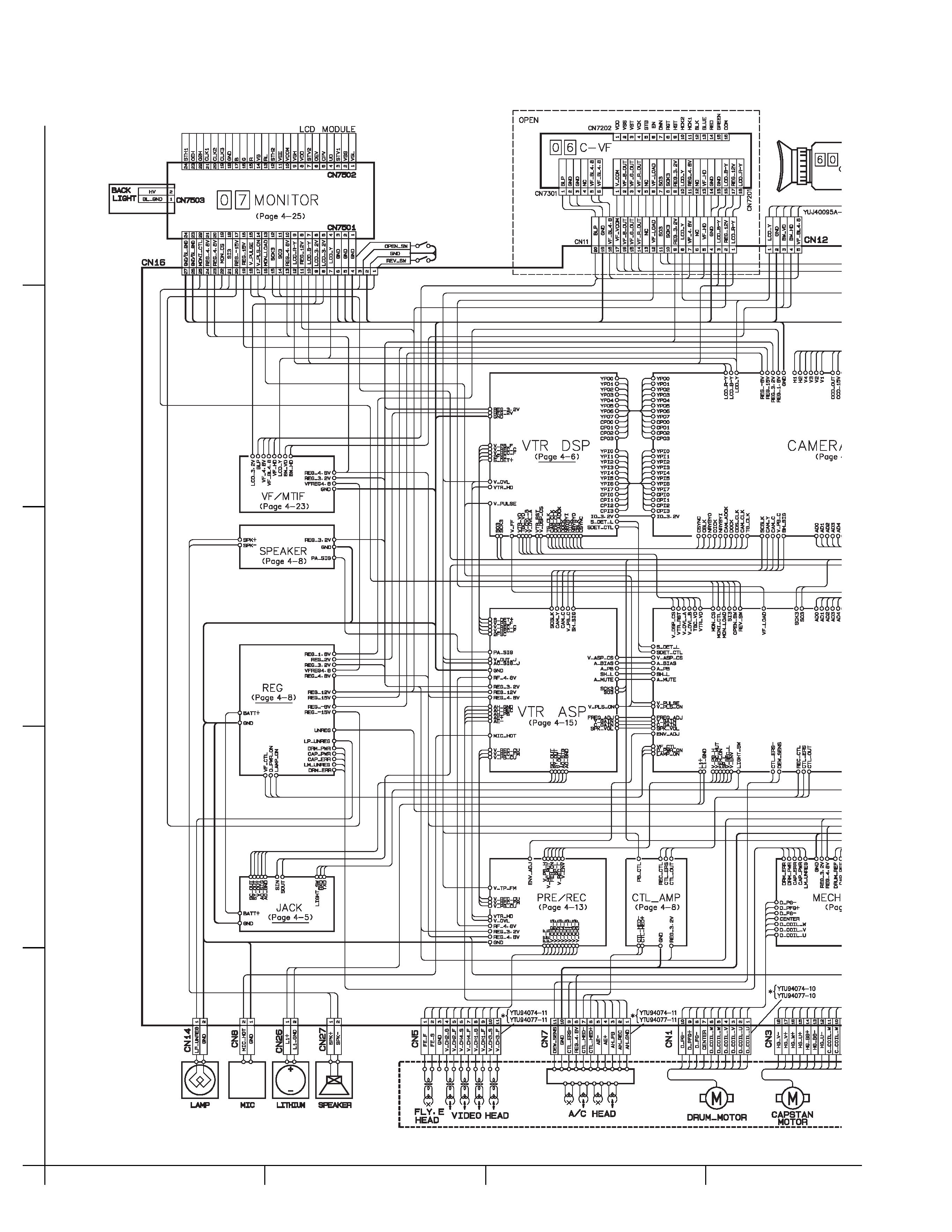
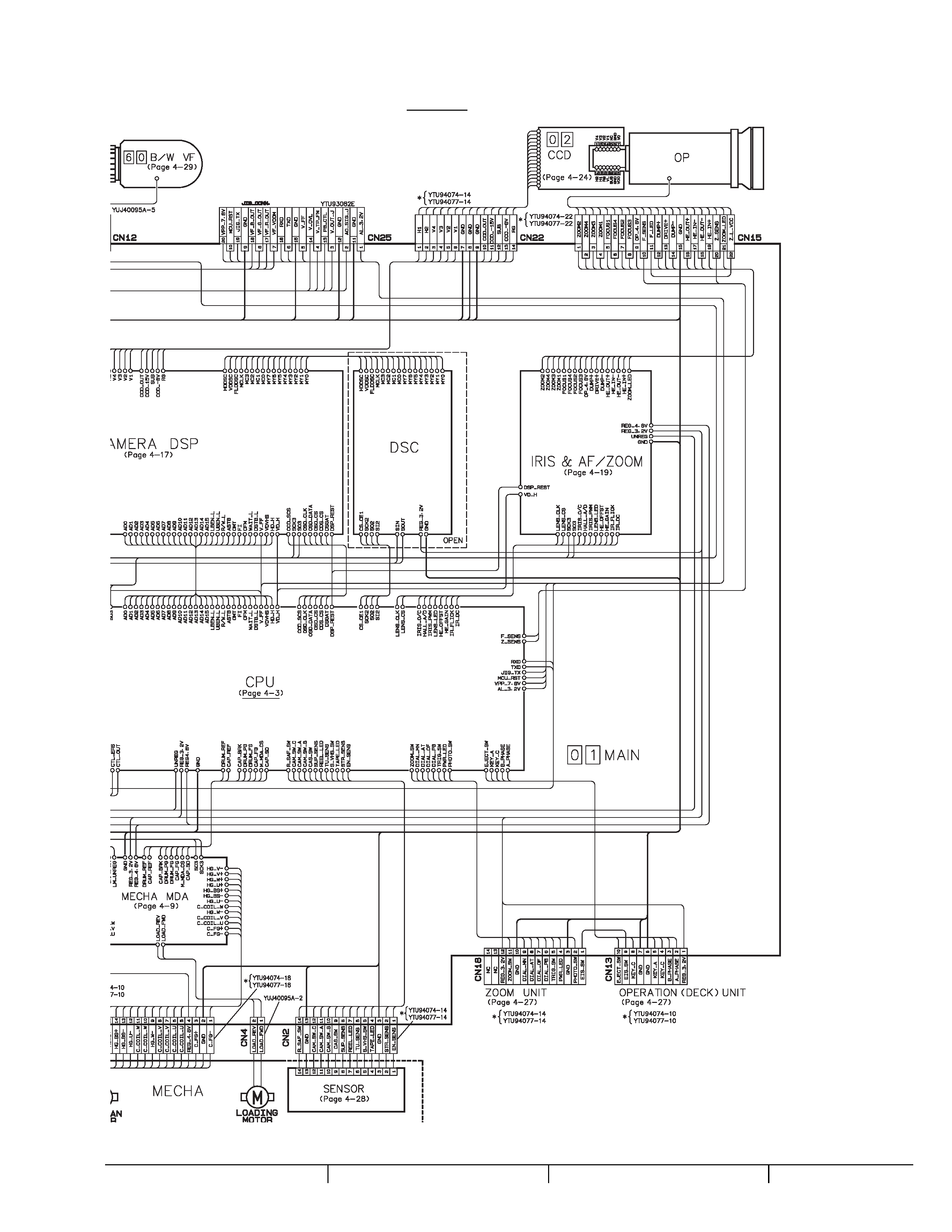
4.1
BOARD INTERCONNECTIONS
SECTION 4
CHARTS AND DIAGRAMS
4-2
EF
G
H
Note: How to find the page showing the continuative schematic diagram
Example) TO REG (Page 4-22): Refer to the GR-AXM220U service manaul (No. 86526)
TO REG (Page 4-9):
Refer to this service manual