SERVICE MANUAL
No.86572
June 2000
GC-X1E-S/E-BK/E-BL/E-RD/EK-S/EA
DIGITAL STILL CAMERA
SPECIFICATIONS
STILL CAMERA
Power source
Power consumption
Dimensions
Weight
Operating temperature
Relative humidity
Storage temperature
LCD screen
Storage media
CCD
Focal distance
Lens
Video
Recording format
Sensitivity
Iris value (F value)
Exposure control
Exposure compensation
Minimum subject distance
Light measurement system
Flash
Recommended distance for flash
Shutter speed
White balance
Focus
: DC 5 V
: 4.0 W (when the LCD screen is off)
5.6 W (when the LCD screen is on)
: 101 (W) mm x 67 (H) mm x 59 (D) mm
(except protruding parts)
: Approx. 290 g
(without a Memory card and battery)
:0
°C to 40°C
: 35% to 80%
: 20
°C to 50°C
: 2.0 inch, polysilicon TFT (200,000 pixels)
: SmartMediaTM 3.3V (up to 64MB)
: 3.34 million pixels (3.24 million valid pixels),
1/1.8" square pixels, primary color filter,
interlace scan CCD
: 7.5 mm to 17.5 mm
(equivalent to 37mm to 86 mm on a 35 mm still camera)
: 2.3X optical zoom lens
: 160 pixels x 120 pixels, 20 seconds, JVC original format
: Exif Ver. 2.1 (DCF compliant), TIFF (Uncompressed),
DPOF-compatible
: 80/160/320 (ISO compliant)
: F2.8/3.8, 5.6, 8, 11
: Program AE, iris priority AE
: +/2EV (0.5EV steps)
: Approx. 2 cm to 50 cm (in Macro mode)
: Multi, spot
: Built-in,
Auto/red-eye prevention/forced/disabled
: Approx. 2.5 m
: Auto (Program AE: 1/8 seconds 1/750 seconds,
Iris priority AE: 1/4 seconds 1/750 seconds )
: Auto/Manual ( ,
,
, MWB,
)
: Auto/Manual
Self timer
Photo quality
Number of storable photos
(with an 8MB Memory card,
STANDARD/FINE/NO COMP.)
Battery
Printer connector
VIDEO output connector
Digital output connector
: 1 second, 8 seconds
: 3 modes (STANDARD/FINE/NO COMP.)
: 2032 x 1536: approx. 10/8/0
1024 x 768: approx. 43/32/3
640 x 480: approx. 87/65/8
: Lithium ion battery
: Output for optional printer
: Two-pole plug, 3.5 mm diameter (PAL)
: Mini-USB connector
AC Power Adapter/Charger AA-V37
E. & O. E. Design and specifications subject to change without notice.
: AC 120 V`, 60 Hz
: AC 110 V 240 V`, 50 Hz/60 Hz
: 23 W
: DC 3.6 V
, 0.77 A
: DC 5.0 V
, 1.5 A
:0
°C to 40°C [when charging: 10°C to 35°C]
: 68 (W) mm x 38 (H) mm x 110 (D) mm
: Approx. 230 g (without a DC cord)
Power requirement
U.S.A. and Canada
Other countries
Power consumption
Output
Charge
Camera
Operating temperature
Dimensions
Weight

TABLE OF CONTENTS
Section
Title
Page
Section
Title
Page
I
mportant Safety Precautions
1. DISASSEMBLY
1.1
BEFORE ASSEMBLY AND DISASSEMBLY .................... 1-1
1.1.1 Precautions ................................................................. 1-1
1.1.2 Assembly and disassembly ......................................... 1-1
1.1.3 Disconnection of Connectors (Wires) ......................... 1-2
1.2
TOOLS AND EQUIPMENTS REQUIRED FOR ADJUSTMENTS ............ 1-2
1.2.1 Tools required for adjustments ................................... 1-2
1.3
DISASSEMBLY /ASSEMBLY OF CABINET PARTS ......... 1-2
1.3.1 Disassembly flow chart ............................................... 1-2
1.3.2 Disassembly method ( I ) ............................................ 1-3
1.3.3 Disassembly method ( II ) <OP UNIT> ....................... 1-6
1.3.4 OP BLOCK Lens composition ..................................... 1-7
1.4
IC BLOCK DIAGRAM ...................................................... 1-8
1.4.1 IC 1002 (CXD2497R) ................................................... 1-8
1.4.2 IC 2001 (CDS/AGL) ..................................................... 1-9
1.4.3 IC 7302 (CXA3268AR) ............................................... 1-10
1.4.4 LCD (ACX301AK) ...................................................... 1-11
1.4.5 CCD (ICX262AQ) ....................................................... 1-12
2. ELECTRICAL ADJUSTMENT
2.1
ELECTRICAL ADJUSTMENT .......................................... 2-1
2.1.1 Precautions ................................................................. 2-1
2.1.2 Test instruments required for electrical adjustment ............. 2-1
2.1.3 Required test equipment ............................................ 2-1
2.1.4 Setup (LCD ADJUSTMENT) ........................................ 2-1
2.1.5 Setup (CCD ADJUSTMENT) ....................................... 2-2
2.2
Setup with patch cords and jig connector cables ............ 2-3
3. CHARTS AND DIAGRAMS
NOTES OF SCHEMATIC DIAGRAM ........................................ 3-1
CIRCUIT BOARD NOTES ......................................................... 3-2
3.1
BOARD INTERCONNECTION ......................................... 3-3
3.2
MAIN (SYSCON) SCHEMATIC DIAGRAM ...................... 3-5
3.3
MAIN (DSP96) SCHEMATIC DIAGRAM .......................... 3-7
3.4
MAIN (DSP97) SCHEMATIC DIAGRAM .......................... 3-9
3.5
MAIN (G/A JCY0148) AND
MAIN (SD SUB) SCHEMATIC DIAGRAM ........... 3-11
3.6
MAIN (F/Z MDA) AND
MAIN (IRIS) SCHEMATIC DIAGRAMS ............... 3-12
3.7
MAIN (CDS AGC A/D AND ARM ROM)
SCHEMATIC DIAGRAM ..................................... 3-13
3.8
MAIN (STROBE CONTROL AND STROBE FLASH)
SCHEMATIC DIAGRAM ..................................... 3-14
3.9
CCD SCHEMATIC DIAGRAM ........................................ 3-15
3.10 MONI REG (MONITOR) SCHEMATIC DIAGRAM ......... 3-16
3.11 MONITOR REG (DC/DC) SCHEMATIC DIAGRAM ........ 3-17
3.12 JACK (VIDEO OUT/USB/PRINTER/DC JACK) AND
MONITOR BACK LIGHT SCHEMATIC DIAGRAM ..... 3-19
3.13 VOLTAGE CHARTS ........................................................ 3-20
3.14 MAIN CIRCUIT BOARD (YB10282-01-06) ..................... 3-23
3.15 MONITOR REG CIRCUIT BOARD (YB10283-01-02) ..... 3-29
3.16 MONITOR REG CIRCUIT BOARD (YB10283-01-04) ..... 3-31
3.17 JACK CIRCUIT BOARD (YB10283-01-02) ..................... 3-33
3.18 JACK CIRCUIT BOARD (YB10283-01-04) ..................... 3-35
3.19 CCD CIRCUIT BOARD (YB10283-01-02) ....................... 3-37
3.20 CCD CIRCUIT BOARD (YB10283-01-04) ....................... 3-38
3.21 STOROBE FLASH CIRCUIT BOARD (YB10283-01-02) ...... 3-39
3.22 STOROBE FLASH CIRCUIT BOARD (YB10283-01-04) ...... 3-40
3.23 OVER ALL BLOCK DIAGRAM ....................................... 3-41
3.24 POWER SUPPLY BLOCK DIAGRAM ............................ 3-43
3.25 OP BLOCK SCHEMATIC DIAGRAM <REFERENCE> .. 3-45
3.26 OPERATION UINT
SCHEMATIC DIAGRAM <REFERENCE> .......... 3-46
4. PARTS LIST
4.1
PACKING AND ACCESSORY ASSEMBLY <M1> ........... 4-1
4.2
OP BLOCK ASSEMBLY <M3> ........................................ 4-2
4.3
FINAL ASSEMBLY <M2> .............................................. 4-3
4.4
ELECTRICAL PARTS LIST ............................................... 4-6
MAlN BOARD ASSEMBLY <01> .................................... 4-6
CCD BOARD ASSEMBLY <02> .................................... 4-11
MONI REG BOARD ASSEMBLY <03> ......................... 4-12
JACK BOARD ASSEMBLY <04> .................................. 4-14
STROBE FLASH BOARD ASSEMBLY <05> ................. 4-15
5. AC POWER ADAPTER (AA-V37E/EK/EA)
5.1
CABINET ASSEMBLY <MA> .......................................... 5-1
5.2
SCHEMATIC DIAGRAM .................................................. 5-2
5.3
CIRCUIT BOARD ............................................................. 5-4
5.4
ELECTRICAL PARTS LIST ............................................... 5-5
MAIN AND TERMINAL BOARD ASSEMBLY <91> ........ 5-5
Operating Environment
The host computer that runs the Macintosh®
operating environment must satisfy the following
conditions.
USB Driver
1. USB-compatible computer (iMacTM, iBookTM,
Power MacTM G3/G4, Power BookTM G3, etc.)
2. Mac OS 8.5.1/Mac OS 8.6/Mac OS 9.0
JVC Video Decoder
1. Power PC 603e/120MHz or faster
2. Mac OS 7.6.1 or later
3. QuickTime 3.0 or later
4. Minimum RAM requirement: 32MB
5. Minimum hard disk space requirement: 1MB
* Macintosh® is a registered trademark of Apple
Computer.
* Other trademarks are property of their
owners.
* If you use Macintosh® which does not have a
port, use an optional flash path, conversion
adapter, etc. For details on the operating en
ment of these devices, contact the dealers or
manufacturers.
Operating Environment
The host computer that runs the Windows®
operating environment must satisfy the following
conditions.
USB Driver
1. Microsoft® Windows® 98/Windows® 98 Second
Edition, pre-installed
2. Available USB port
3. CD-ROM drive
Video Player
1. CPU: Intel® Pentium® 200MHz class or higher
2. Microsoft® Windows® 95/Windows® 98
3. Display capability of 65,536 colors or more
4. CD-ROM drive
5. Minimum RAM requirement: 32MB
6. Minimum hard disk space requirement: 1MB
* The system requirements information is not a
guarantee that provided software applications will
work on all personal computers meeting those
requirements.
* Microsoft®, Windows® are either registered
trademarks or trademarks of Microsoft corporation
in United States and/or other countries.
* Intel®, Pentium® are registered trademarks of Intel
corporation.
* Other trademarks are property of their respective
owners.
* If you use Windows® 95 or a personal computer
which does not have a USB port, use an optional
flash path, conversion card adapter, etc. For
details on the operating environment of these
devices, contact the dealers or manufacturers.
SOFTWARE SECTION FOR Macintosh®
SOFTWARE SECTION FOR Windows®
The following table lists the differing points between Models GC-X1E-S, GC-X1E-BK, GC-X1E-BL, GC-XE-RD, GC-X1EK-S/GC-X1EA in this
series.
E-S
E-BK
E-BL
E-RD
EK-S
EA
AC POWER ADAPTER
AA-V37E
++
+
AA-V37EK
AA-V37EA
Important Safety Precautions
Prior to shipment from the factory, JVC products are strictly inspected to conform with the recognized product safety and electrical codes
of the countries in which they are to be sold. However, in order to maintain such compliance, it is equally important to implement the
following precautions when a set is being serviced.
Fig.1
1. Locations requiring special caution are denoted by labels and
inscriptions on the cabinet, chassis and certain parts of the
product. When performing service, be sure to read and com-
ply with these and other cautionary notices appearing in the
operation and service manuals.
2. Parts identified by the
symbol and shaded (
) parts are
critical for safety.
Replace only with specified part numbers.
Note: Parts in this category also include those specified to com-
ply with X-ray emission standards for products using
cathode ray tubes and those specified for compliance
with various regulations regarding spurious radiation
emission.
3. Fuse replacement caution notice.
Caution for continued protection against fire hazard.
Replace only with same type and rated fuse(s) as specified.
4. Use specified internal wiring. Note especially:
1) Wires covered with PVC tubing
2) Double insulated wires
3) High voltage leads
5. Use specified insulating materials for hazardous live parts.
Note especially:
1) Insulation Tape
3) Spacers
5) Barrier
2) PVC tubing
4) Insulation sheets for transistors
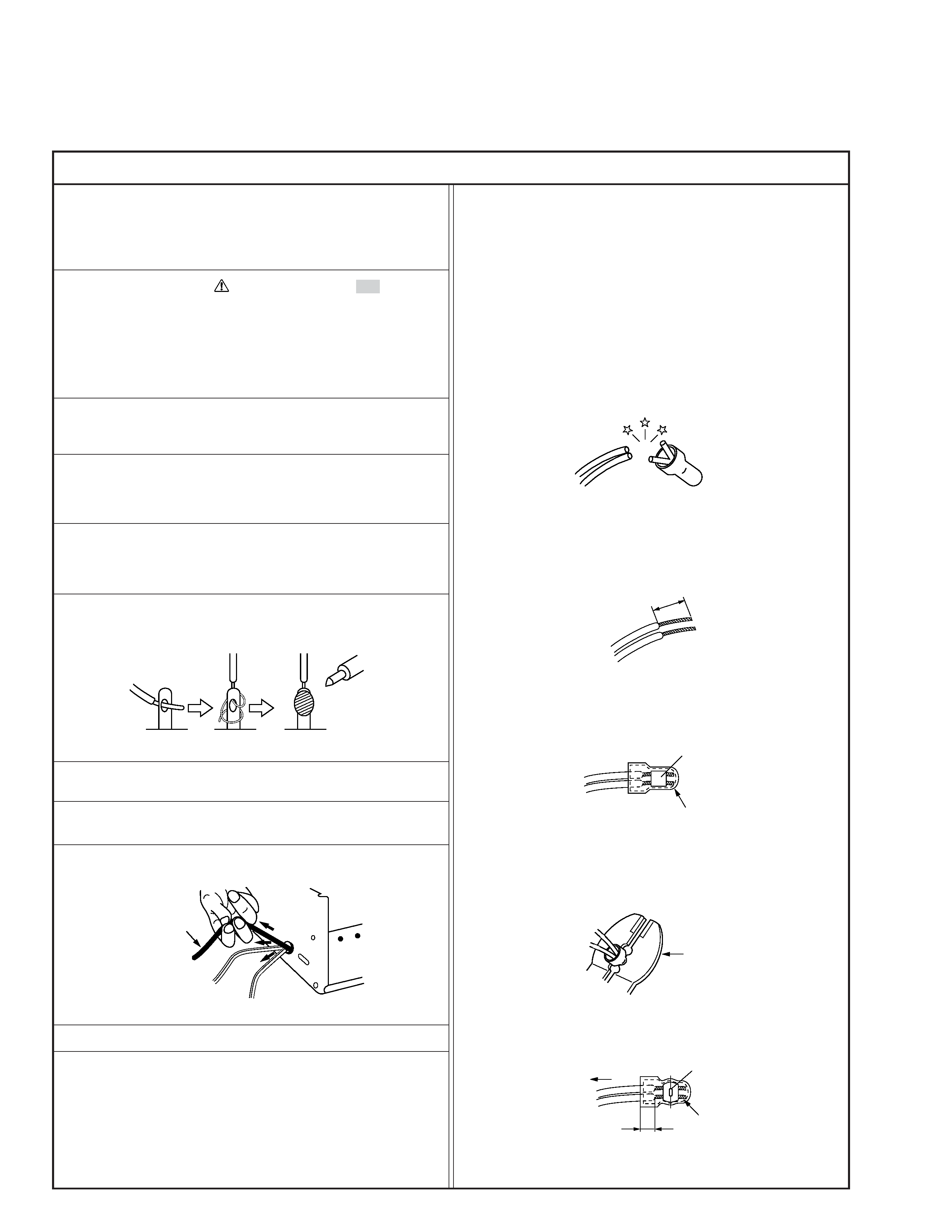
6. When replacing AC primary side components (transformers,
power cords, noise blocking capacitors, etc.) wrap ends of
wires securely about the terminals before soldering.
Power cord
Fig.2
10. Also check areas surrounding repaired locations.
11. Products using cathode ray tubes (CRTs)
In regard to such products, the cathode ray tubes themselves,
the high voltage circuits, and related circuits are specified for
compliance with recognized codes pertaining to X-ray emission.
Consequently, when servicing these products, replace the cath-
ode ray tubes and other parts with only the specified parts.
Under no circumstances attempt to modify these circuits.
Unauthorized modification can increase the high voltage value
and cause X-ray emission from the cathode ray tube.
12. Crimp type wire connector
In such cases as when replacing the power transformer in sets
where the connections between the power cord and power
transformer primary lead wires are performed using crimp type
connectors, if replacing the connectors is unavoidable, in or-
der to prevent safety hazards, perform carefully and precisely
according to the following steps.
1) Connector part number : E03830-001
2) Required tool : Connector crimping tool of the proper type
which will not damage insulated parts.
3) Replacement procedure
(1) Remove the old connector by cutting the wires at a point
close to the connector.
Important : Do not reuse a connector (discard it).
Fig.7
cut close to connector
Fig.3
(2) Strip about 15 mm of the insulation from the ends of
the wires. If the wires are stranded, twist the strands to
avoid frayed conductors.
15 mm
Fig.4
(3) Align the lengths of the wires to be connected. Insert
the wires fully into the connector.
Connector
Metal sleeve
Fig.5
(4) As shown in Fig.6, use the crimping tool to crimp the
metal sleeve at the center position. Be sure to crimp fully
to the complete closure of the tool.
1
Precautions during Servicing
7. Observe that wires do not contact heat producing parts
(heatsinks, oxide metal film resistors, fusible resistors, etc.)
8. Check that replaced wires do not contact sharp edged or
pointed parts.
9. When a power cord has been replaced, check that 10-15 kg of
force in any direction will not loosen it.
1.25
2.0
5.5
Crimping tool
Fig.6
(5) Check the four points noted in Fig.7.
Not easily pulled free
Crimped at approx. center
of metal sleeve
Conductors extended
Wire insulation recessed
more than 4 mm
S40888-01
Safety Check after Servicing
Examine the area surrounding the repaired location for damage or deterioration. Observe that screws, parts and wires have been
returned to original positions, Afterwards, perform the following tests and confirm the specified values in order to verify compli-
ance with safety standards.
1. Insulation resistance test
Confirm the specified insulation resistance or greater between power cord plug prongs and
externally exposed parts of the set (RF terminals, antenna terminals, video and audio input
and output terminals, microphone jacks, earphone jacks, etc.). See table 1 below.
2. Dielectric strength test
Confirm specified dielectric strength or greater between power cord plug prongs and exposed
accessible parts of the set (RF terminals, antenna terminals, video and audio input and output
terminals, microphone jacks, earphone jacks, etc.). See table 1 below.
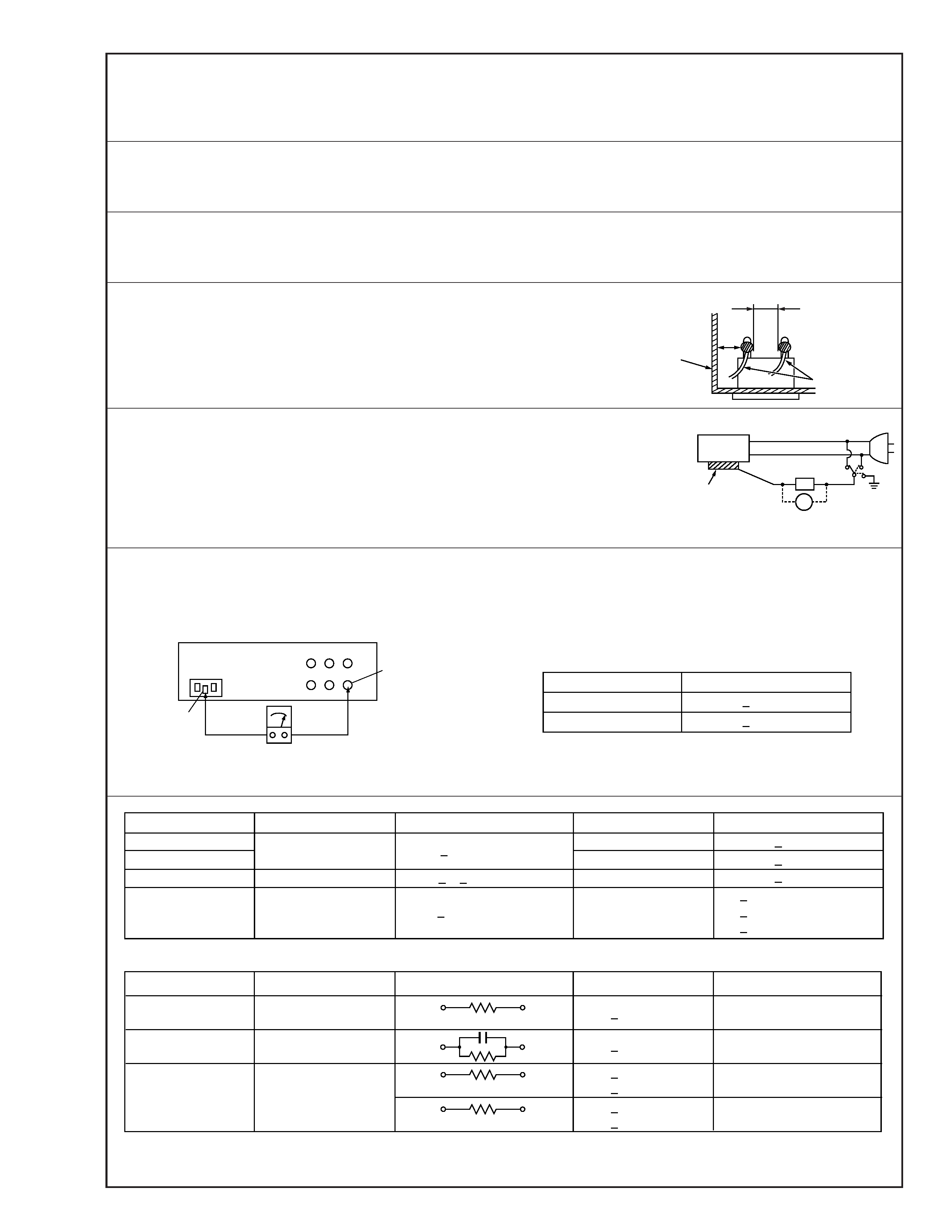
3. Clearance distance
When replacing primary circuit components, confirm specified clearance distance (d), (d') be-
tween soldered terminals, and between terminals and surrounding metallic parts. See table 1
below.
4. Leakage current test
Confirm specified or lower leakage current between earth ground/power cord plug prongs
and externally exposed accessible parts (RF terminals, antenna terminals, video and audio
input and output terminals, microphone jacks, earphone jacks, etc.).
Measuring Method : (Power ON)
Insert load Z between earth ground/power cord plug prongs and externally exposed accessi-
ble parts. Use an AC voltmeter to measure across both terminals of load Z. See figure 9 and
following table 2.
5. Grounding (Class 1 model only)
Confirm specified or lower grounding impedance between earth pin in AC inlet and externally exposed accessible parts (Video in,
Video out, Audio in, Audio out or Fixing screw etc.).
Measuring Method:
Connect milli ohm meter between earth pin in AC inlet and exposed accessible parts. See figure 10 and grounding specifications.
d'
d
Chassis
Power cord,
primary wire
Region
USA & Canada
Europe & Australia
Grounding Impedance (Z)
Z
0.1 ohm
Z
0.5 ohm
AC inlet
Earth pin
Exposed accessible part
Milli ohm meter
Grounding Specifications
Fig. 10
ab
c
V
Externally
exposed
accessible part
Z
Fig. 9
Fig. 8
Clearance Distance (d), (d')
d, d'
3 mm
d, d'
4 mm
d, d'
3.2 mm
1 M
R 12 M/500 V DC
Dielectric Strength
AC 1 kV 1 minute
AC 1.5 kV 1 miute
AC 1 kV 1 minute
AC Line Voltage
100 V
100 to 240 V
110 to 130 V
110 to 130 V
200 to 240 V
Japan
USA & Canada
Europe & Australia
R
10 M
/500 V DC
Region
Insulation Resistance (R)
R
1 M
/500 V DC
AC 3 kV 1 minute
(Class
2)
AC 1.5 kV 1 minute
(Class
1)
d
4 mm
d'
8 mm (Power cord)
d'
6 mm (Primary wire)
Table 1 Specifications for each region
a, b, c
Leakage Current (i)
AC Line Voltage
100 V
110 to 130 V
110 to 130 V
220 to 240 V
Japan
USA & Canada
i
1 mA rms
Exposed accessible parts
Exposed accessible parts
Antenna earth terminals
Other terminals
i
0.5 mA rms
i
0.7 mA peak
i
2 mA dc
i
0.7 mA peak
i
2 mA dc
Europe & Australia
Region
Load Z
1 k
2 k
1.5 k
0.15
µF
50 k
Table 2 Leakage current specifications for each region
Note: These tables are unofficial and for reference only. Be sure to confirm the precise values for your particular country and locality.
2
S40888-01
