1-1
FS-P5
SERVICE MANUAL
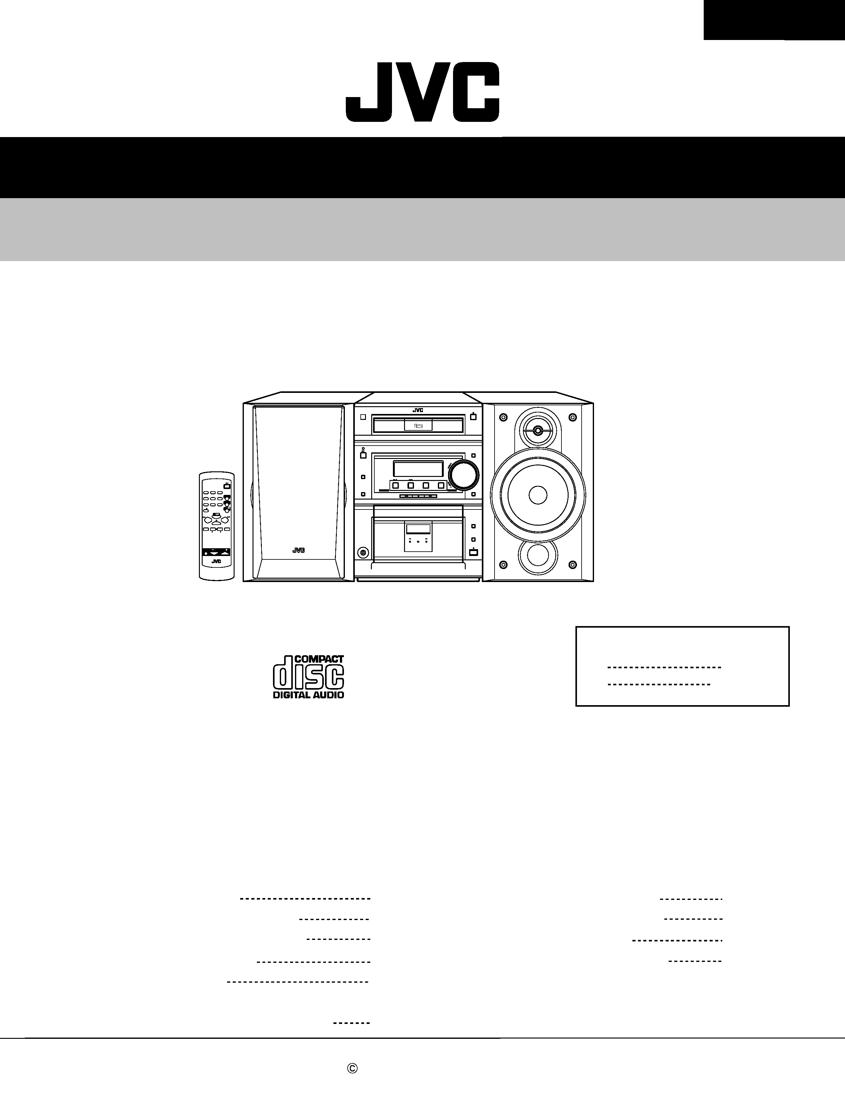
MICRO COMPONENT SYSTEM
No.21001
Jun. 2001
COPYRIGHT
2001 VICTOR COMPANY OF JAPAN, LTD.
FS-P5
FS-P5
Contents
Safety precautions
Preventing static electricity
Important for laser products
Disassembly method
Main adjustment
Flow of functional operation
until TOC read (CD)
Maintenance of laser pickup
Replacement of laser pickup
Description of major ICs
Internal connection of display
1-2
1-4
1-6
1-7
1-15
1-19
1-20
1-20
1-21
1-40
Area Suffix
J
C
U.S.A.
Canada
SP-UXP5
CA-FSP5
SP-UXP5
SLEEP
STANDBY/ON
MD/AUX
FM/AM
TAPE
CD
DISPLAY
DIMMER
REPEAT
RANDOM
PROG
FM MODE
AUTO
PRESET
SOUND
MODE
CD
CANCEL
MULTI KEY
SET
RM-SUXP5U REMOTE CONTROL
VOLUME
AHB
PRO
COMPACT
DIGITAL AUDIO
CD
TAPE
FM/AM
COMP ACT
COMPONENT
SYSTEM
FS·P5
CD-R/R W PLA YBACK
MD/AUX
TIMER
CLOCK
STANDBY/ON
STANDBY
/ ON
VOLUME
FUNCTION
SOUND
DIRECT OPERATING
AHB PRO
REC
REV.MODE
PHONES
AUTO REVERSE
REC
/
1-2
FS-P5
1. This design of this product contains special hardware and many circuits and components specially for safety
purposes. For continued protection, no changes should be made to the original design unless authorized in
writing by the manufacturer. Replacement parts must be identical to those used in the original circuits. Services
should be performed by qualified personnel only.
2. Alterations of the design or circuitry of the product should not be made. Any design alterations of the product
should not be made. Any design alterations or additions will void the manufacturer`s warranty and will further
relieve the manufacture of responsibility for personal injury or property damage resulting therefrom.
3. Many electrical and mechanical parts in the products have special safety-related characteristics. These
characteristics are often not evident from visual inspection nor can the protection afforded by them necessarily
be obtained by using replacement components rated for higher voltage, wattage, etc. Replacement parts which
have these special safety characteristics are identified in the Parts List of Service Manual. Electrical
components having such features are identified by shading on the schematics and by (
) on the Parts List in
the Service Manual. The use of a substitute replacement which does not have the same safety characteristics
as the recommended replacement parts shown in the Parts List of Service Manual may create shock, fire, or
other hazards.
4. The leads in the products are routed and dressed with ties, clamps, tubings, barriers and the like to be
separated from live parts, high temperature parts, moving parts and/or sharp edges for the prevention of
electric shock and fire hazard. When service is required, the original lead routing and dress should be
observed, and it should be confirmed that they have been returned to normal, after re-assembling.
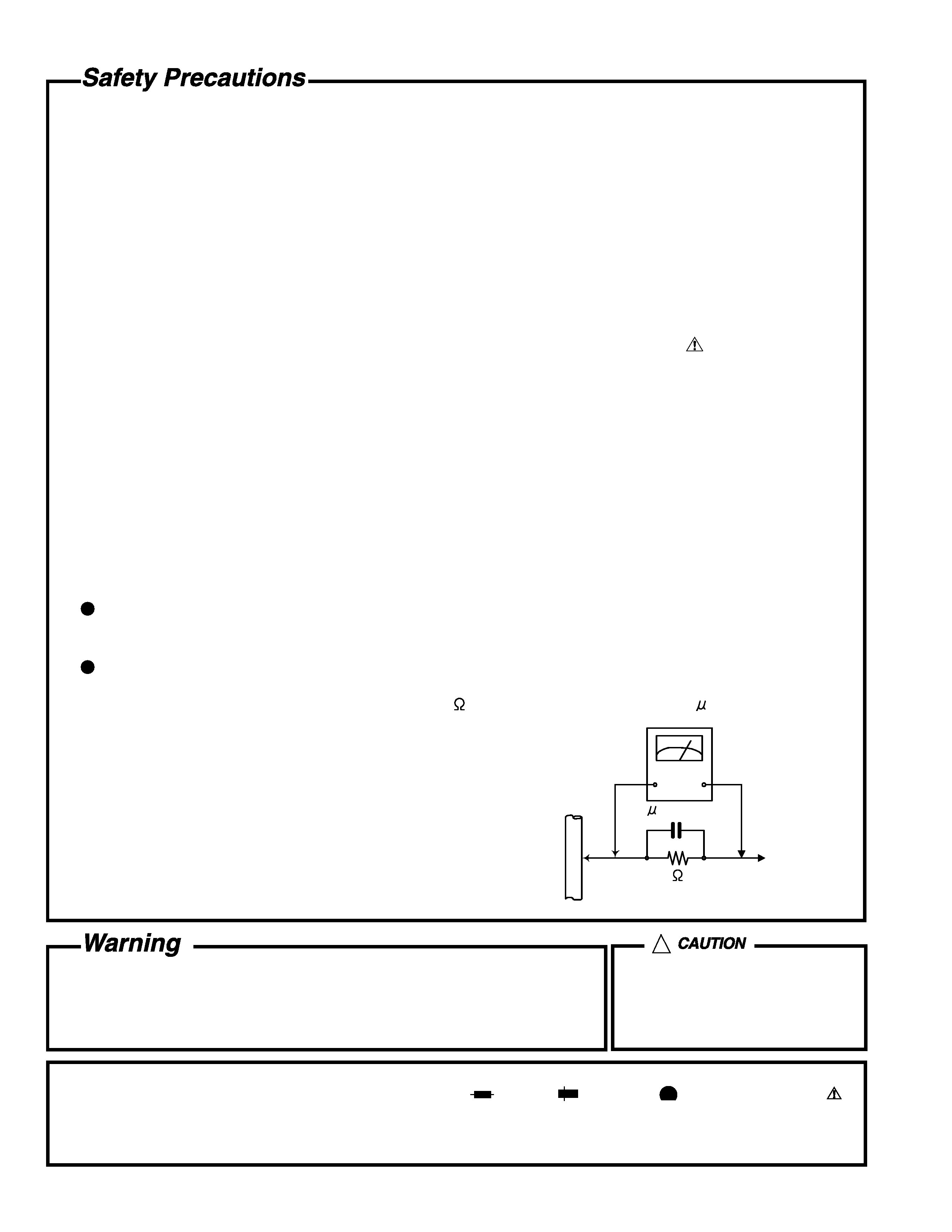
5. Leakage currnet check (Electrical shock hazard testing)
After re-assembling the product, always perform an isolation check on the exposed metal parts of the product
(antenna terminals, knobs, metal cabinet, screw heads, headphone jack, control shafts, etc.) to be sure the
product is safe to operate without danger of electrical shock.
Do not use a line isolation transformer during this check.
Plug the AC line cord directly into the AC outlet. Using a "Leakage Current Tester", measure the leakage
current from each exposed metal parts of the cabinet, particularly any exposed metal part having a return
path to the chassis, to a known good earth ground. Any leakage current must not exceed 0.5mA AC (r.m.s.).
Alternate check method
Plug the AC line cord directly into the AC outlet. Use an AC voltmeter having, 1,000 ohms per volt or more
sensitivity in the following manner. Connect a 1,500
10W resistor paralleled by a 0.15 F AC-type capacitor
between an exposed metal part and a known good earth ground.
Measure the AC voltage across the resistor with the AC
voltmeter.
Move the resistor connection to eachexposed metal part,
particularly any exposed metal part having a return path to
the chassis, and meausre the AC voltage across the resistor.
Now, reverse the plug in the AC outlet and repeat each
measurement. Voltage measured any must not exceed 0.75 V
AC (r.m.s.). This corresponds to 0.5 mA AC (r.m.s.).
1. This equipment has been designed and manufactured to meet international safety standards.
2. It is the legal responsibility of the repairer to ensure that these safety standards are maintained.
3. Repairs must be made in accordance with the relevant safety standards.
4. It is essential that safety critical components are replaced by approved parts.
5. If mains voltage selector is provided, check setting for local voltage.
Good earth ground
Place this
probe on
each exposed
metal part.
AC VOLTMETER
(Having 1000
ohms/volts,
or more sensitivity)
1500
10W
0.15 F AC TYPE
!
Burrs formed during molding may
be left over on some parts of the
chassis. Therefore, pay attention to
such burrs in the case of
preforming repair of this system.
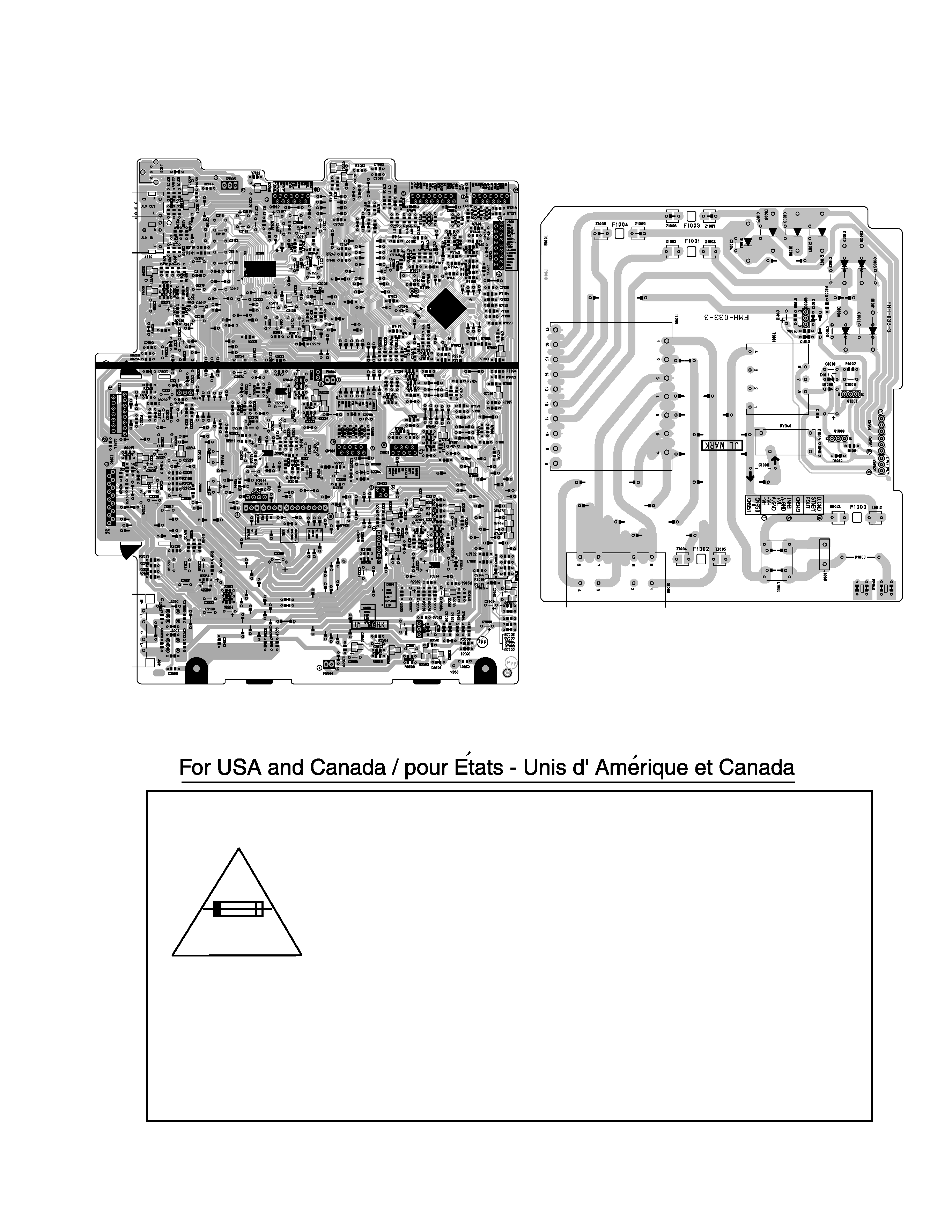
In regard with component parts appearing on the silk-screen printed side (parts side) of the PWB diagrams, the
parts that are printed over with black such as the resistor (
), diode (
) and ICP (
) or identified by the " "
mark nearby are critical for safety.
When replacing them, be sure to use the parts of the same type and rating as specified by the manufacturer.
(Except the J and C version)
1-3
FS-P5
Caution: For continued protection against risk of
fire, replace only with same type 2.5A/125V for
F1000,1A/125V for F3000,5A/125V for F1001,F1003
and F1004. This symbol specifies type of fast
operating fuse.
Precaution: Pour eviter risques de feux, remplacez
le fusible de surete de F1000 comme le meme type
que 2.5A/125V,et 1A/125V pour F3000,et 5A/125V
pour F1001 et F1003 et F1004.Ce sont des fusibles
suretes qui functionnes rapide.
Importance administering point on the safety
1-4
FS-P5
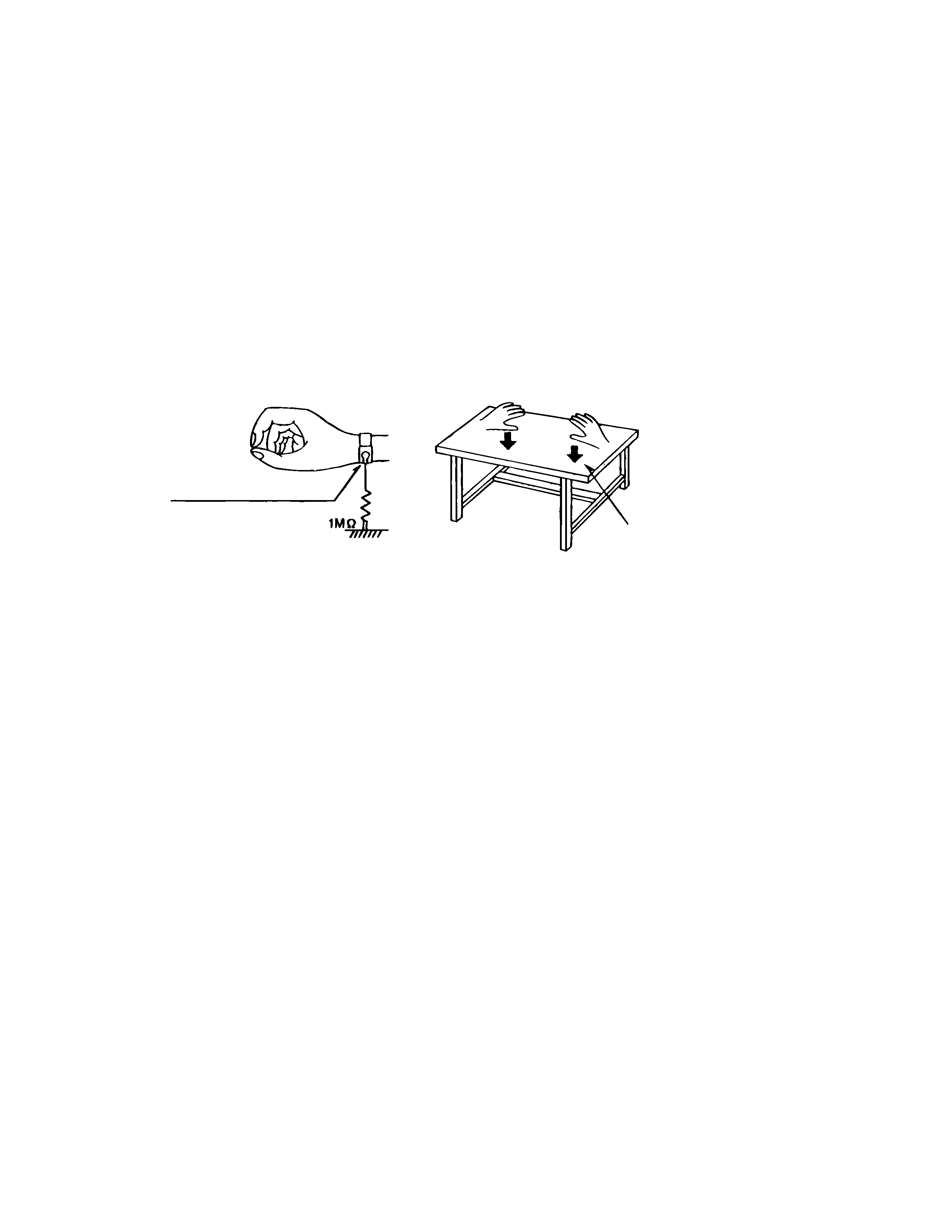
Preventing static electricity
Electrostatic discharge (ESD), which occurs when static electricity stored in the body, fabric, etc. is discharged,
can destroy the laser diode in the traverse unit (optical pickup). Take care to prevent this when performing repairs.
1.1. Grounding to prevent damage by static electricity
Static electricity in the work area can destroy the optical pickup (laser diode) in devices such as DVD players.
Be careful to use proper grounding in the area where repairs are being performed.
1.1.1. Ground the workbench
1. Ground the workbench by laying conductive material (such as a conductive sheet) or an iron plate over
it before placing the traverse unit (optical pickup) on it.
1.1.2. Ground yourself
1. Use an anti-static wrist strap to release any static electricity built up in your body.
1.1.3. Handling the optical pickup
1. In order to maintain quality during transport and before installation, both sides of the laser diode on the
replacement optical pickup are shorted. After replacement, return the shorted parts to their original condition.
(Refer to the text.)
2. Do not use a tester to check the condition of the laser diode in the optical pickup. The tester's internal power
source can easily destroy the laser diode.
1.2. Handling the traverse unit (optical pickup)
1. Do not subject the traverse unit (optical pickup) to strong shocks, as it is a sensitive, complex unit.
2. Cut off the shorted part of the flexible cable using nippers, etc. after replacing the optical pickup. For specific
details, refer to the replacement procedure in the text. Remove the anti-static pin when replacing the traverse
unit. Be careful not to take too long a time when attaching it to the connector.
3. Handle the flexible cable carefully as it may break when subjected to strong force.
4. It is not possible to adjust the semi-fixed resistor that adjusts the laser power. Do not turn it
Conductive material
(conductive sheet) or iron plate
(caption)
Anti-static wrist strap
1-5
FS-P5
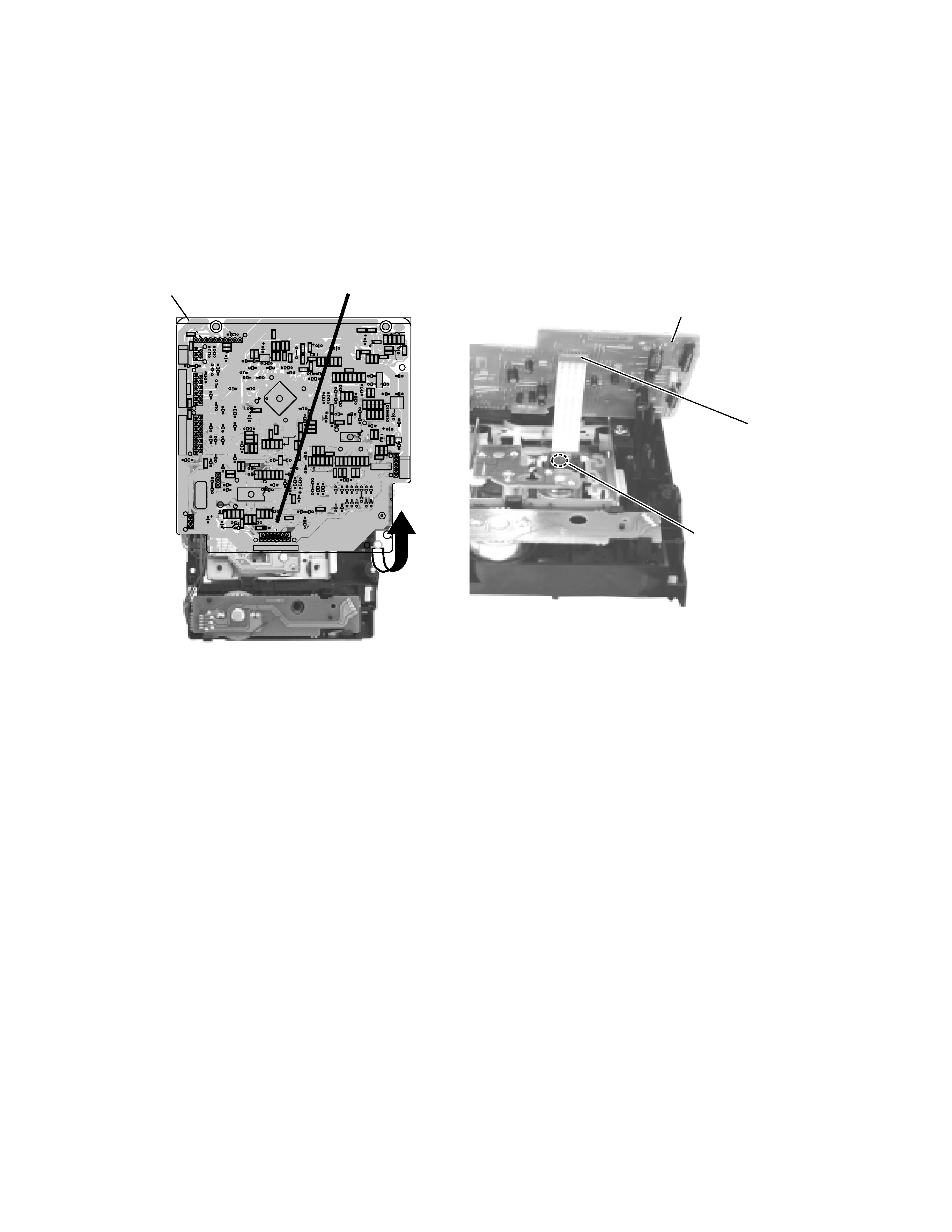
1.3. Cautions on removing the CD traverse unit
* For removing the CD traverse unit in detail, refer to the "Adjustment Method" section of this manual.
1. Before disconnecting the flexible wire from the connector CN601 on the CD SERVO board, solder the part shown in
the figure below.
(Note:If the flexible wire is disconnected from the CN601 without presoldering, it may cause breakdown of the CD
pickup assembly.)
2. When reassembling the CD traverse unit, be sure to remove the solder from the soldered part after reconnecting the
flexible wire to the CN601.
CD SERVO board
CD SERVO board
Soldering part
CN601
CN601
C601
C602
C603
C604
C605
C606
C607
C610
C611
C612
C613
C614
C615
C616
C617
C619
C620
C621
C622
C623
C624
C631
C632
C633
C641
C642
C643
B619
C651
C652
C653
C654
C655
C656
C657
C658
C661
C663
C664
C665
C667
C668
C669
C670
C671
C672
C673
C676
C677
C679
C680
C691
C692
C693
C694
C695
C696
C699
C801
C802
C811
C812
C813
C814
C815
C821
C822
C823
C824
C831
C832
C833
CN601
CN651
CN652
CN801
D831
R648
IC652
IC801
IC802
L831
Q631
Q801
R601
R602
R603
R604
R605
R606
R610
R611
R612
R613
R617
R618
R619
R620
R621
R631
R632
R634
R635
R636
R641
R642
R643
R647
R651
R652
R653
R654
R655
R656
R657
R658
R659
R661
R662
R663
R664
R665
R666
R667
R668
R669
R670
R682
R683
R685
R691
R692
R695
R696
R701
R702
R703
R704
R705
R706
R707
R708
R709
R710
R801
R802
R803
R804
R805
R806
R807
R808
R809
R812
R821
R822
R823
R824
R831
W605
CN606
X651
B604
B616
B614
R813
C816
B613
B615
B610
B612
B617
B618
IC601
R607
B601
B603
B602
B611
B609
B608
B607
B606
B605
D601
D602
R681
C681
R684
MUTE
FLAG
CDDG
BLKCK
/REST
MLD
MDATA
MCLK
CDDG
SUBQ
SQCK
/RST
STAT
FM+
REST
SM-
SM+
D.GND
FM-
1
1
1
1
1
B
E
B
E
C
31
6
ARF
A.GND
F-
T-
T+
F+
GND
VR
LD
MD
T2
K
F1
NC
T1
SR
F2
115
T02
SCD
SCD
CDDG
13
LM+
OPSW
GND
CLSW
LM-
M.GND
SW10
SW10
CLOSE
OPEN
OPSW
CLSE
CD+B
CD+B
CDL
A.GND
A.GND
CDR
5
1
1
16
1
21
41
61
17
16
32
12
24
13