* Design and specifications subject to change without notice.
Camera head section
s Image sensing device
: 1/3-inch IT-CCD (410,000 pixels)
s Shooting system
: 4-CCD new dual green system
s Colour separation optical
system
: 1/3 type F1.4 3-colour separation prism
s Number of effective pixels
: 768 (horizontal) x 494 (vertical), 380,000 pixels
s Camera output
: 19 pins
s Lens mount
: Special mount (C mount form, flange back: 28.0 mm)
s Dimensions
: Camera head; 59 (W) x 70 (H) x 79 (D) mm
(2-3/8" x 2-13/16" x 3-1/8")
(not including insulating rubber covers)
s Weight
: Camera head; 230 g (0.51 lbs.) (not including
insulating rubber covers)
s Classification
: Type BF
Camera control unit section
s Number of scanning lines
: 1125 (980 effective)
s Scanning system
: 2:1 interlace
s Scanning frequency
: 33.75 kHz (horizontal), 60 Hz (vertical)
sAspect ratio
: 4:3
s Horizontal resolution (center) : More than 800 TV lines (Y signal)
s Vertical resolution (center)
: More than 650 TV lines (Y signal)
s S/N
: 52 dB
s Sensitivity
: F5.6, 2000 lx
s Minimum subject illuminance : 10 lx (F1.6 + 12 dB, 1/30 shutter, 50% level)
s Sync system
: Internal sync/external sync
s External sync signal input
: Composite video signal of 1 Vp-p or composite sync
signal of
±0.3 Vp-p, 75 ohms, BNC x 1
s Colour bar
: Full colour bar
s Contour correction
: Horizontal dual-edged (9-step variable)
Vertical dual-edged (9-step variable)
s Electronic shutter speed
: 1/30 s, 1/60 s (normal), 1/100 s (flicker-free),
1/175 s, 1/250 s, 1/375 s, 1/500 s, 1/1000 s,
1/2000 s
s Video output
· R/G/B signal
: 0.7 Vp-p, 75 ohms for each (no sync), BNC
connector x 3 (one for each)
· Y/PB/PR
Y
: 1 Vp-p, 75 ohms (including sync)
PB
: 0.7 Vp-p, 75 ohms (including sync)
PR
: 0.7 Vp-p, 75 ohms (including sync)
· Sync signal
: HD; BNC x 1 (TTL)
VD, BNC x 1 (TTL)
C. SYNC; BNC x 1
(
±0.3 Vp-p, 75 ohms, compliant with HDTV
standard ITU-R Rec. 709)
TECHNICAL AND SERVICE
ASSISTANCE
JVC offers technical and customer service assistance.
Please contact us at the following address.
JVC PROFESSIONAL PRODUCTS (UK) LIMITED
ULLswater House, Kendel Avenue, London W3 OXA,
United Kingdom
TEL: (0181) 896-6000
FAX: (0181) 896-6060
JVC PROFESSIONAL PRODUCTS GmbH
Grüner Weg 10, 61169 Fiedberg/Hessen, Germany
TEL: (06031) 6050
FAX: (06031) 605180
s SCSI Interface
: 50 pin mini x 2
s Camera input
: 20 pins
s Date indication
: Menu system
1) Year, month, day
2) Day, month, year
3) Month, day, year
s Time indication
: Menu system,
hour: minute: second
s Power supply
: DC 12 V, 1.3 A XLR 4 pins, AA-V112E AC
power adaptor (optional)
When using this unit for medical purposes, be
absolutely sure to use the separately sold
AA-V31E isolation transformer.
s Power consumption
: 18 W
s Operating environment
:+5
°C to +35°C (41°F to 95°F), 35 75%
s Allowable storage environment : 20
°C to +50°C (4°F to 122°F), 35 80%
s Dimensions
: 430 (W) x 93 (H) x 322 (D) mm
(16-15/16" x 3-11/16" x 12-11/16")
(excluding the handle for rack mounting)
s Weight
: 4.9 kg (10.8 lbs.)
s Accessories
: Handle set x 1
s Supplied documentation
: Instruction manual x 1
Warrantee card x 1
Service center information x 1
VICTOR COMPANY OF JAPAN, LIMITED
VIDEO DIVISION
Printed in Japan
S40894
MICRO HD CAMERA
DZ-VCA1SE
No. 86536
May 2001
This service manual is printed on 100% recycled paper.
COPYRIGHT
© 2001 VICTOR COMPANY OF JAPAN, LTD.
SPECIFICATIONS
DZ-VCA1SE
No.
86536

Important Safety Precautions
INSTRUCTIONS
1. PRECAUTIONS ON SERVICING
1.1
BEFORE DISASSEMBLING AND REASSEMBLING ......... 1-1
1.1.1
Precautions .................................................................. 1-1
1.1.2
Disassembly of optical block assembly ....................... 1-1
1.2
PREPARATION AND PRELIMINARY CHECK
REQUIRED FOR ADJUSTMENT ....................................... 1-1
1.2.1
Before adjustment ....................................................... 1-1
1.2.2
Tools and jigs required for repair and adjustment ....... 1-1
1.
Tools and test instruments necessary for check
and adjustment ............................................................ 1-1
2.
Standard setup ............................................................ 1-2
3.
Complementary explanation of functions of internal
switches of boards (CCU section) ............................... 1-2
2.
ELECTRICAL ADJUSTMENT
2.1
ADJUSTMENT OF CAMERA .............................................. 2-1
2.1.1
Initial setting ................................................................. 2-1
1.
Standard shooting conditions ...................................... 2-1
2.
Functions and initial settings of internal switches of
boards (CCU section) .................................................. 2-1
2.1.2
Adjustment procedure ................................................. 2-2
1.
Standard adjustment procedure .................................. 2-2
2.
Adjustment procedure at installation
(On attaching lens to camera) ..................................... 2-2
3.
Adjustment procedure at camera head replacement ... 2-2
2.1.3
Adjustment of camera head ......................................... 2-3
1.
Reset bias .................................................................... 2-3
2.
G1/G2-ch DL gain ........................................................ 2-3
3.
Vsub voltage ................................................................ 2-4
2.1.4
Adjustment of CCU section ......................................... 2-4
1.
Initial setting of CCU section ....................................... 2-4
2.
Pedestal level .............................................................. 2-5
3.
Input gain ..................................................................... 2-5
4.
Knee level .................................................................... 2-6
5.
Clock phase ................................................................. 2-7
6.
Encoder Y signal level ................................................. 2-7
7.
Encoder Y sync signal level ......................................... 2-8
8.
Encoder Pb signal evel ................................................ 2-9
9.
Encoder Pr signal level ................................................ 2-9
10. Encoder Pb gain ........................................................ 2-10
11. Encoder B gain .......................................................... 2-11
12. Encoder Pr gain ......................................................... 2-11
13. Encoder R gain .......................................................... 2-12
14. Encoder Y/R gain ...................................................... 2-13
15. Encoder G gain .......................................................... 2-13
16. R gain for tint adjustment ........................................... 2-14
17. B gain for tint adjustment ........................................... 2-15
18. G1 and G2 balance (horizontal) ................................ 2-15
19. G1 and G2 balance (vertical) ..................................... 2-16
20. G1 and G2 balance (fine adjustment) ........................ 2-17
21. Automatic AGC .......................................................... 2-17
22. Automatic DC balance ............................................... 2-18
23. Gen-lock PLL ............................................................. 2-18
24. Dynamic shading ....................................................... 2-19
2.1.5
Setting of white balance ............................................ 2-19
3. INSTALLATION MANUAL
INSTALLATION MANUAL ................................................... 3-1
TABLE OF CONTENTS
Section
Title
Page
Section
Title
Page
4. CHARTS AND DIAGRAMS
NOTES OF SCHEMATIC DIAGRAM .................................. 4-1
CIRCUIT BOARD NOTES .................................................. 4-2
4.1
BOARD INTERCONNECTIONS ......................................... 4-3
4.2
CAMERA UNIT BLOCK DIAGRAM .................................... 4-5
4.3
CCD BLOCK DIAGRAAM ................................................... 4-7
4.4
ANALOG SCHEMATIC DIAGRAM ..................................... 4-9
4.5
ADC SCHEMATIC DIAGRAM ........................................... 4-11
4.6
DSP1 SCHEMATIC DIAGRAM ......................................... 4-13
4.7
DSP2 SCHEMATIC DIAGRAM ......................................... 4-15
4.8
MICOM SCHEMATIC DIAGRAM ...................................... 4-17
4.9
SVP SCHEMATIC DIAGRAM ........................................... 4-19
4.10
MTX SCHEMATIC DIAGRAM ........................................... 4-21
4.11
MAIN CIRCUIT BOARD .................................................... 4-23
4.12
POWER SCHEMATIC DIAGRAM ..................................... 4-35
4.13
POWER CIRCUIT BOARD (YB10204-01-01) ................... 4-37
4.14
FCP SCHEMATIC DIAGRAM ........................................... 4-39
4.15
FCP CIRCUIT BOARD ...................................................... 4-41
4.16
DR SCHEMATIC DIAGRAM ............................................. 4-43
4.17
PA SCHEMATIC DIAGRAM ............................................. 4-45
4.18
TG SCHEMATIC DIAGRAM ............................................. 4-47
4.19
DR CIRCUIT BOARD ........................................................ 4-49
4.20
PA CIRCUIT BOARD ........................................................ 4-50
4.21
TG CIRCUIT BOARD ........................................................ 4-51
4.22
I/O1, I/O2 AND LED SCHEMATIC DIAGRAMS ................ 4-52
4.23
I/O1, I/O2 AND LED CIRCUIT BOARDS .......................... 4-53
4.24
ISB AND ISG1 SCHEMATIC DIAGRAMS ........................ 4-54
4.25
ISB AND ISG1 CIRCUIT BOARDS ................................... 4-55
4.26
ISG2 AND ISR SCHEMATIC DIAGRAMS ........................ 4-56
4.27
ISG2 AND ISR CIRCUIT BOARDS ................................... 4-57
5. PARTS LIST
5.1
PACKING AND ACCESSORY ASSEMBLY <M1> ............. 5-1
5.2
CAMERA CABI. AND OP BLOCK ASSEMBLY <M2> ........ 5-2
5.3
CAMERA CONTROL UNIT ASSEMBLY <M3> .................. 5-3
5.4
ELECTRICAL PARTS LIST ................................................ 5-7
MAIN BOARD ASSEMBLY <01> ........................................ 5-7
POWER BOARD ASSEMBLY <02> ................................. 5-20
FCP BOARD ASSEMBLY <03> ........................................ 5-21
I/O1 BOARD ASSEMBLY <04> ........................................ 5-22
I/O2 BOARD ASSEMBLY <05> ........................................ 5-23
LED BOARD ASSEMBLY <06> ........................................ 5-23
PA BOARD ASSEMBLKY <07> ........................................ 5-23
ISB BOARD ASSEMBLY <08> ......................................... 5-24
ISG1 BOARD ASSEMBLY <09> ....................................... 5-24
ISG2 BOARD ASSEMBLY <10> ....................................... 5-24
ISR BOARD ASSEMBLY <11> ......................................... 5-25
DR BOARD ASSEMBLY <12> .......................................... 5-25
TG BOARD ASSEMBLY <13> .......................................... 5-26

The DZ-VCA1SE installed for medical use requires a special service manner different from that for general
use.
When servicing the DZ-VCA1SE for medical use, pay heed to the following points.
1. Pre- and post-service sterilization is required.
2. Isolation transwarmer is needed.
3. Leak current is different from that for general use.
4. Service history must be put on record.
When installing the DZ-VCA1SE, carefully proceed to it following the instructions of the installation guide.
<Example of system configuration for medical use>
DZ-VCA1SE
+
Isolation transwarmer
+
AC power adapter
+
Camera cable
+
Microscope adapter
<Example of system configuration for general use>
DZ-VCA1SE
+
AC power adapter
+
Camera cable
+
Microscope adapter
Important Safety Precautions
Prior to shipment from the factory, JVC products are strictly inspected to conform with the recognized product safety and electrical codes
of the countries in which they are to be sold. However, in order to maintain such compliance, it is equally important to implement the
following precautions when a set is being serviced.
Fig.1
1. Locations requiring special caution are denoted by labels and
inscriptions on the cabinet, chassis and certain parts of the
product. When performing service, be sure to read and com-
ply with these and other cautionary notices appearing in the
operation and service manuals.
2. Parts identified by the
symbol and shaded (
) parts
such as fuses and circuit protectors are critical for safety.
Replace only with specified part numbers.
3. Fuse replacement caution notice.
Caution for continued protection against fire hazard.
Replace only with same type and rated fuse(s) as specified.
4. Use specified internal wiring. Note especially:
1) Wires covered with PVC tubing
2) Double insulated wires
3) High voltage leads
5. Use specified insulating materials for hazardous live parts.
Note especially:
1) Insulation Tape
3) Spacers
5) Barrier
2) PVC tubing
4) Insulation sheets for transistors
6. When replacing AC primary side components (transformers,
power cords, noise blocking capacitors, etc.) wrap ends of
wires securely about the terminals before soldering.
Power cord
Fig.2
10. Also check areas surrounding repaired locations.
11. Products using cathode ray tubes (CRTs)
In regard to such products, the cathode ray tubes themselves,
the high voltage circuits, and related circuits are specified for
compliance with recognized codes pertaining to X-ray emission.
Consequently, when servicing these products, replace the cath-
ode ray tubes and other parts with only the specified parts.
Under no circumstances attempt to modify these circuits.
Unauthorized modification can increase the high voltage value
and cause X-ray emission from the cathode ray tube.
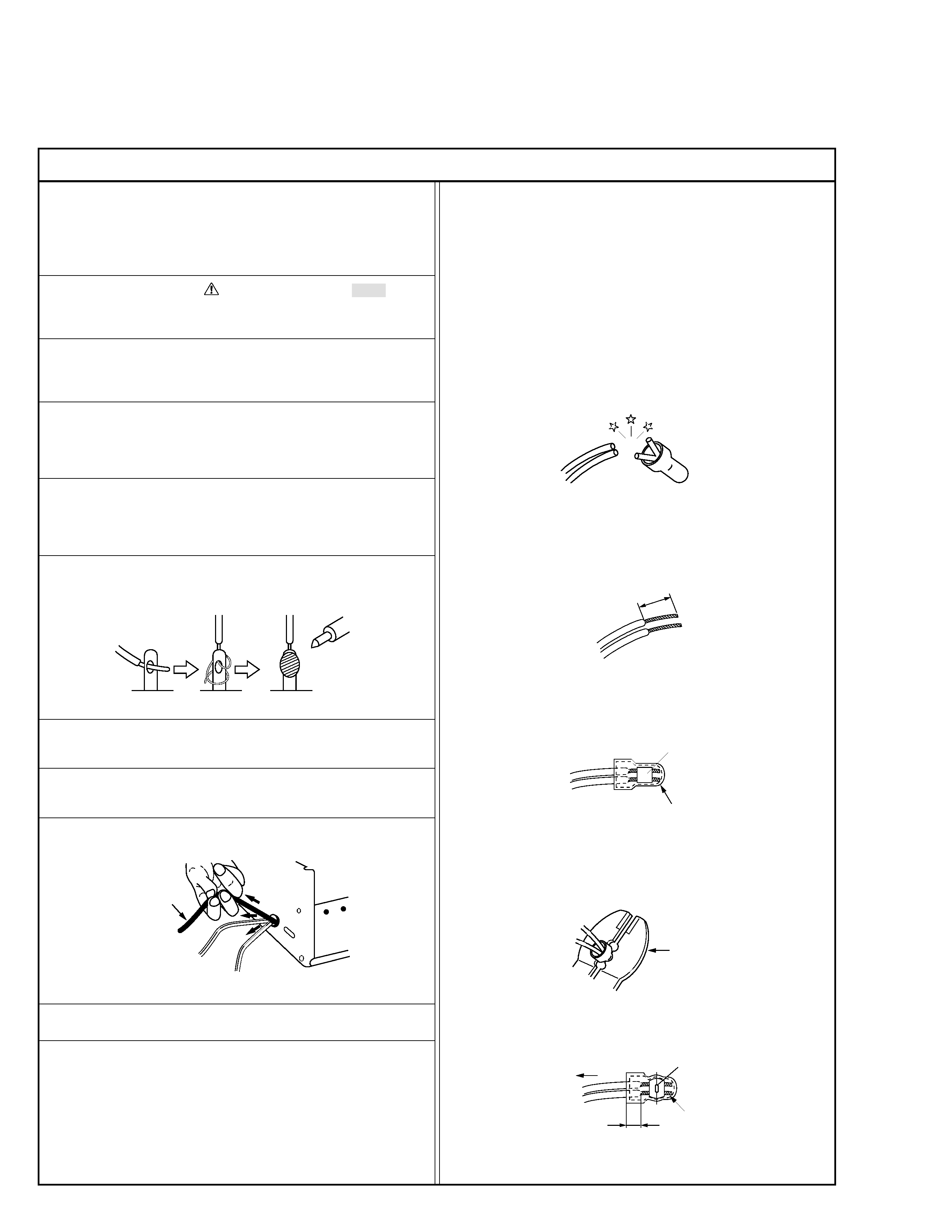
12. Crimp type wire connector
In such cases as when replacing the power transformer in sets
where the connections between the power cord and power
transformer primary lead wires are performed using crimp type
connectors, if replacing the connectors is unavoidable, in or-
der to prevent safety hazards, perform carefully and precisely
according to the following steps.
1) Connector part number : E03830-001
2) Required tool : Connector crimping tool of the proper type
which will not damage insulated parts.
3) Replacement procedure
(1) Remove the old connector by cutting the wires at a point
close to the connector.
Important : Do not reuse a connector (discard it).
Fig.7
cut close to connector
Fig.3
(2) Strip about 15 mm of the insulation from the ends of
the wires. If the wires are stranded, twist the strands to
avoid frayed conductors.
15 mm
Fig.4
(3) Align the lengths of the wires to be connected. Insert
the wires fully into the connector.
Connector
Metal sleeve
Fig.5
(4) As shown in Fig.6, use the crimping tool to crimp the
metal sleeve at the center position. Be sure to crimp fully
to the complete closure of the tool.
1
Precautions during Servicing
7. Observe that wires do not contact heat producing parts
(heatsinks, oxide metal film resistors, fusible resistors, etc.)
8. Check that replaced wires do not contact sharp edged or
pointed parts.
9. When a power cord has been replaced, check that 10-15 kg of
force in any direction will not loosen it.
1.25
2.0
5.5
Crimping tool
Fig.6
(5) Check the four points noted in Fig.7.
Not easily pulled free
Crimped at approx. center
of metal sleeve
Conductors extended
Wire insulation recessed
more than 4 mm
Safety Check after Servicing
Examine the area surrounding the repaired location for damage or deterioration. Observe that screws, parts and wires have been
returned to original positions, Afterwards, perform the following tests and confirm the specified values in order to verify compli-
ance with safety standards.
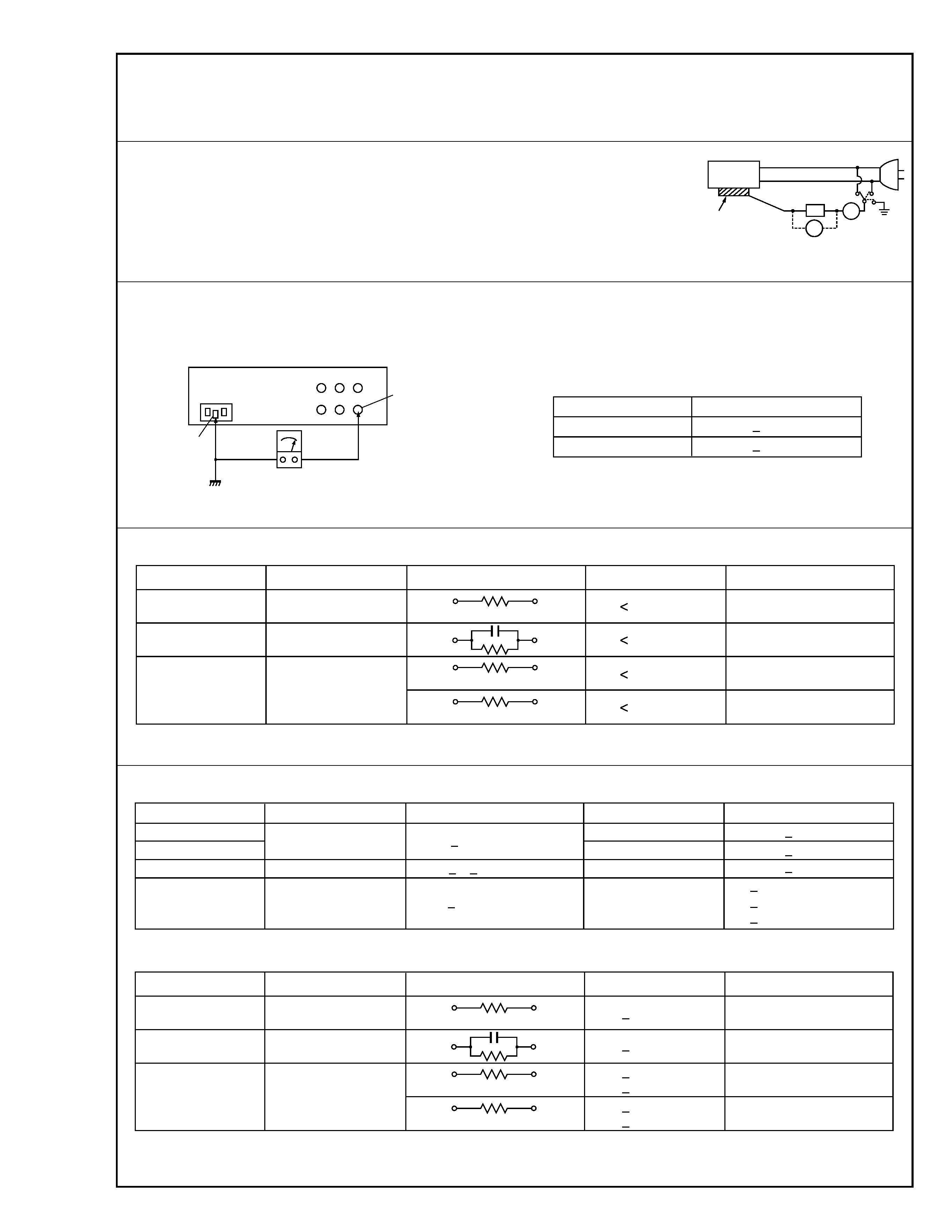
1. Leakage current test
Confirm specified or lower leakage current between earth ground/power cord plug prongs
and externally exposed accessible parts (RF terminals, antenna terminals, video and audio
input and output terminals, microphone jacks, earphone jacks, etc.).
Measuring Method : (Power ON)
Insert load Z between earth ground/power cord plug prongs and externally exposed accessi-
ble parts. Use an AC voltmeter to measure across both terminals of load Z. See figure 9 and
following table 2.
2. Grounding (Class
1 model only)
Confirm specified or lower grounding impedance between earth pin and externally exposed accessible parts (Video in, Video out,
Audio in, Audio out or Fixing screw etc.).
Measuring Method:
Connect milli ohm meter between earth pin and exposed accessible parts. See figure 10 and grounding specifications.
Region
USA & Canada
Europe & Australia
Grounding Impedance (Z)
Z
0.2 ohm
Z
0.2 ohm
Earth pin
Earth
Exposed accessible part
Milli ohm meter
Grounding Specifications
Fig. 9
ab
c
V
A
Externally
exposed
accessible part
Z
Fig. 8
Clearance Distance (d), (d')
d, d'
3 mm
d, d'
4 mm
d, d'
3.2 mm
1 M
Ø R 12 MØ/500 V DC
Dielectric Strength
AC 1 kV 1 minute
AC 1.5 kV 1 miute
AC 1 kV 1 minute
AC Line Voltage
100 V
100 to 240 V
110 to 130 V
110 to 130 V
200 to 240 V
Japan
USA & Canada
Europe & Australia
R
10 M
Ø/500 V DC
Region
Insulation Resistance (R)
R
1 M
Ø/500 V DC
AC 3 kV 1 minute
(Class
2)
AC 1.5 kV 1 minute
(Class
1)
d
4 mm
d'
8 mm (Power cord)
d'
6 mm (Primary wire)
Table 2 Specifications for each region
a, b, c
Leakage Current ( i )
AC Line Voltage
110 to 130 V
220 to 240 V
Japan
USA & Canada
i
1 mA rms
Exposed accessible parts
Exposed accessible parts
Antenna earth terminals
Other terminals
i
0.5 mA rms
i
0.7 mA peak
i
2 mA dc
i
0.7 mA peak
i
2 mA dc
Europe & Australia
Region
Load Z
1 k
Ø
2 k
Ø
1.5 k
Ø
0.15
µF
50 k
Ø
100 V
110 to 130 V
Table 3 Leakage current specifications for each region
Note: These tables are unofficial and for reference only. Be sure to confirm the precise values for your particular country and locality.
2
< GENERAL USE >
a, b, c
Leakage Current ( i )
AC Line Voltage
110 to 130 V
220 to 240 V
Japan
USA & Canada
Exposed accessible parts
Exposed accessible parts
Antenna earth terminals
Other terminals
Europe & Australia
Region
Load Z
1 k
Ø
2 k
Ø
1.5 k
Ø
0.15
µF
50 k
Ø
100 V
110 to 130 V
i
0.1 mA
i
0.1 mA
i
0.1 mA
i
0.1 mA
Table 1 Leakage current specifications for each region
< MEDICAL USE >