(No.52097)
DT-V1910CG/U
INSTRUCTIONS
DT
-V1910CG
MUL
TI-FORMA
T
MONIT
OR
V
OLUME
SLO
T
1
A
B
DEGA
USS
MENU
MUTING
SCREENS
CHECK
ASPECT
AREA
MARKER
UNDER SCAN
PULSE CR
OSS
COLOR
OFF
SLO
T
2
C
D
SLO
T
3
PO
WER
E
F
INPUT
SELECT
For
Customer
Use:
Enter
below
the
Serial
No.
which
is
located
on
the
rear
of
the
cabinet.
Retain
this
information
for
future
reference.
Model
No.
:
DT
-V1910CG
Serial
No.
:
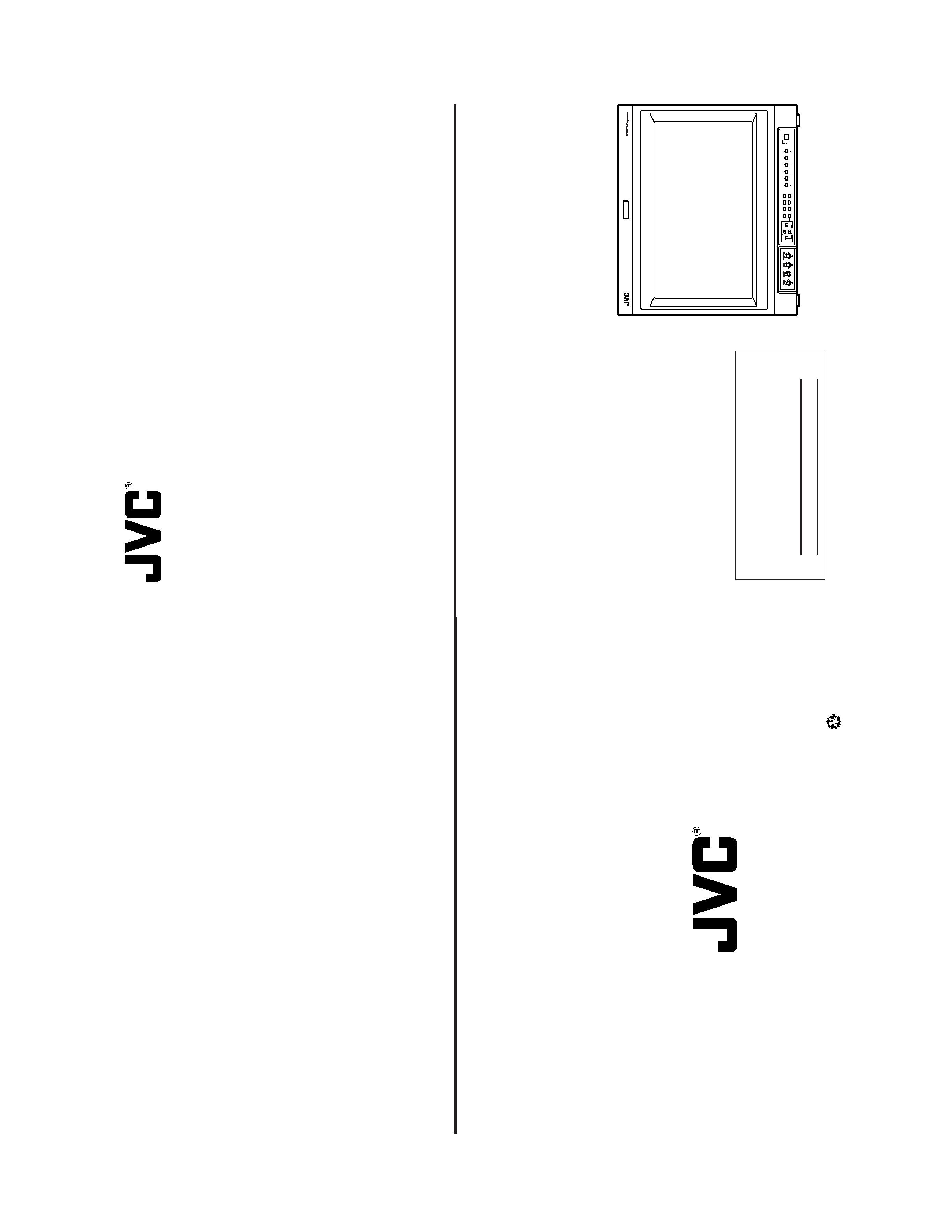
The
illustration
above
shows
the
DT
-V1910CG
with
provided
wide
mask
attached.
LCT1316-001B
JVC
PROFESSIONAL
PRODUCTS
COMPANY
DIVISION
OF
US
JVC
CORP.
1700
Valley
Road
Wayne,
N.J.
07470
JVC
CANADA
INC.
21
Finchdene
Square,
Scarborough
Ontario
M1X
1A7
©
2003
VICT
OR
COMP
ANY
OF
JAP
AN,
LIMITED
Printed
in
Japan
0103-MA-UN-VP
DT-V1910CG MULTI-FORMAT MONITOR
OPERATING INSTRUCTIONS
(No.52097)
DT-V1910CG/U
2
FCC
INFORMATION
(U.S.A.
only)
CAUTION
:Changes
or
modification
not
approved
by
JVC
could
void
the
user's
authority
to
operate
the
equipment.
NOTE:
This
equipment
has
been
tested
and
found
to
comply
with
the
limits
for
a
Class
A
digital
device,
pursuant
to
Part
15
of
the
FCC
Rules.
These
limits
are
designed
to
provide
reasonable
protection
against
harmful
interference
when
the
equipment
is
operated
in
a
commercial
environment.
This
equipment
generates,
uses,
and
can
radiate
radio
frequency
energy
and,
if
not
installed
and
used
in
accordance
with
the
instruction
manual,
may
cause
harmful
interference
to
radio
communications.
Operation
of
this
equipment
in
a
residential
area
is
likely
to
cause
harmful
interference
in
which
case
the
user
will
be
required
to
correct
the
interference
at
his
own
expense.
SCREEN
BURN
It
is
not
recommended
to
keep
a
certain
still
image
displayed
on
screen
for
a
long
time
as
well
as
displaying
extremely
bright
images
on
screen.
This
may
cause
a
burning
(sticking)
phenomenon
on
the
screen
of
cathode-ray
tube.
This
problem
does
not
occur
as
far
as
displaying
normal
video
playback
motion
images.
PRECAUTIONS
Use
only
the
power
source
specified
on
the
unit.
(120
V/230
V
AC,
50
Hz/60
Hz)
Keep
flammable
material,
water
,and
metal
objects
away
from
the
unit
especially
the
interior
of
the
unit.
This
unit
incorporates
high
voltage
circuitry
.
For
your
own
safety
and
that
of
your
equipment,
do
not
attempt
to
modify
or
disassemble
this
monitor
.
There
are
no
user-serviceable
parts
inside.
V
ideo
or
audio
signals
cannot
be
input
to
this
monitor
without
optional
input
cards.
In
these
instructions,
all
explanations
(except
where
noted)
refer
to
the
DT
-V1910CG
with
input
cards
installed.
HANDLING
A
void
shocks
or
vibrations.
These
may
damage
the
unit
and
cause
it
to
malfunction.
Do
not
block
the
ventilation
slots.
Do
not
expose
this
unit
to
high
temperatures.
Extended
exposure
to
direct
sunlight
or
a
heater
could
deform
the
cabinet
or
cause
the
performance
of
internal
components
to
deteriorate.
Do
not
place
the
unit
near
appliances
generating
strong
electric
or
magnetic
fields.
There
can
generate
picture
noise
and
instability
.
Keep
the
monitor
clean
by
wiping
the
cabinet
and
CR
T
screen
with
a
piece
of
soft
cloth.
Do
not
apply
thinner
or
benzine.
These
chemicals
can
damage
the
finish
and
erase
printed
letters.
When
the
unit
is
excessively
dirty
,use
a
diluted
neutral
cleanser
,then
wipe
away
the
cleanser
with
a
dry
cloth.
DEGAUSS
Do
not
use
a
magnet
eraser
to
degauss
the
monitor
's
cathode
ray
tube
from
the
outside.
Doing
so
may
distort
its
aperture
grill
and
cause
a
malfunction.
In
order
to
prevent
any
fatal
accidents
caused
by
misoperation
or
mishandling
the
monitor
,be
fully
aware
of
all
the
following
precautions.
W
ARNINGS
T
o
prevent
fire
or
shock
hazard,
do
not
expose
this
monitor
to
rain
or
moisture.
Dangerous
high
voltages
are
present
inside
the
unit.
Do
not
remove
the
back
cover
of
the
cabinet.
When
servicing
the
monitor
,
consult
qualified
service
personnel.
Never
try
to
service
it
yourself.
W
ARNING
:
THIS
APP
ARA
TUS
MUST
BE
EAR
THED.
This
monitor
is
equipped
with
a
3-blade
grounding-type
plug
to
satisfy
FCC
rule.
If
you
are
unable
to
insert
the
plug
into
the
outlet,
contact
your
electrician.
Improper
operations,
in
particular
alternation
of
high
voltage
or
changing
the
type
of
tube
may
result
in
x-ray
emission
of
considerable
dose.
A
unit
altered
in
such
a
way
no
longer
meets
the
standards
of
certification,
and
must
therefore
no
longer
be
operated.
Notice
(U.S.A.
only)
This
product
utilizes
both
a
Cathode
Ray
T
ube
(CR
T)
and
other
components
that
contain
lead.
Disposal
of
these
materials
may
be
regulated
in
your
community
due
to
environmental
considerations.
For
disposal
or
recycling
information
please
contact
your
local
authorities,
or
the
Electronics
Industries
Alliance:
<http://
www
.eiae.org.>
SAFETY
PRECAUTIONS
3
SAFETY
PRECAUTIONS
........................................................................
2
CONTROLS
AND
FEA
TURES
................................................................
4
CONTROLS
AND
FEA
TURES
(INPU
T
CARD:
OPTIONAL)
..................................................................
7
PREP
ARA
TION
.......................................................................................
9
BASIC
MENU
OPERA
TIONS
(MAIN
MENU,
SETUP
MENU)
............................................................
1
1
HOW
T
O
USE
"MAIN
MENU"
...............................................................
13
HOW
T
O
USE
"SETUP
MENU"
............................................................
16
HOW
T
O
USE
EXTERNAL
CONTROL
.................................................
21
TROUBLESHOOTING
...........................................................................
23
SELF-CHECK
INDICA
TIONS
..............................................................
25
SPECIFICA
TIONS
.................................................................................
26
CONTENTS
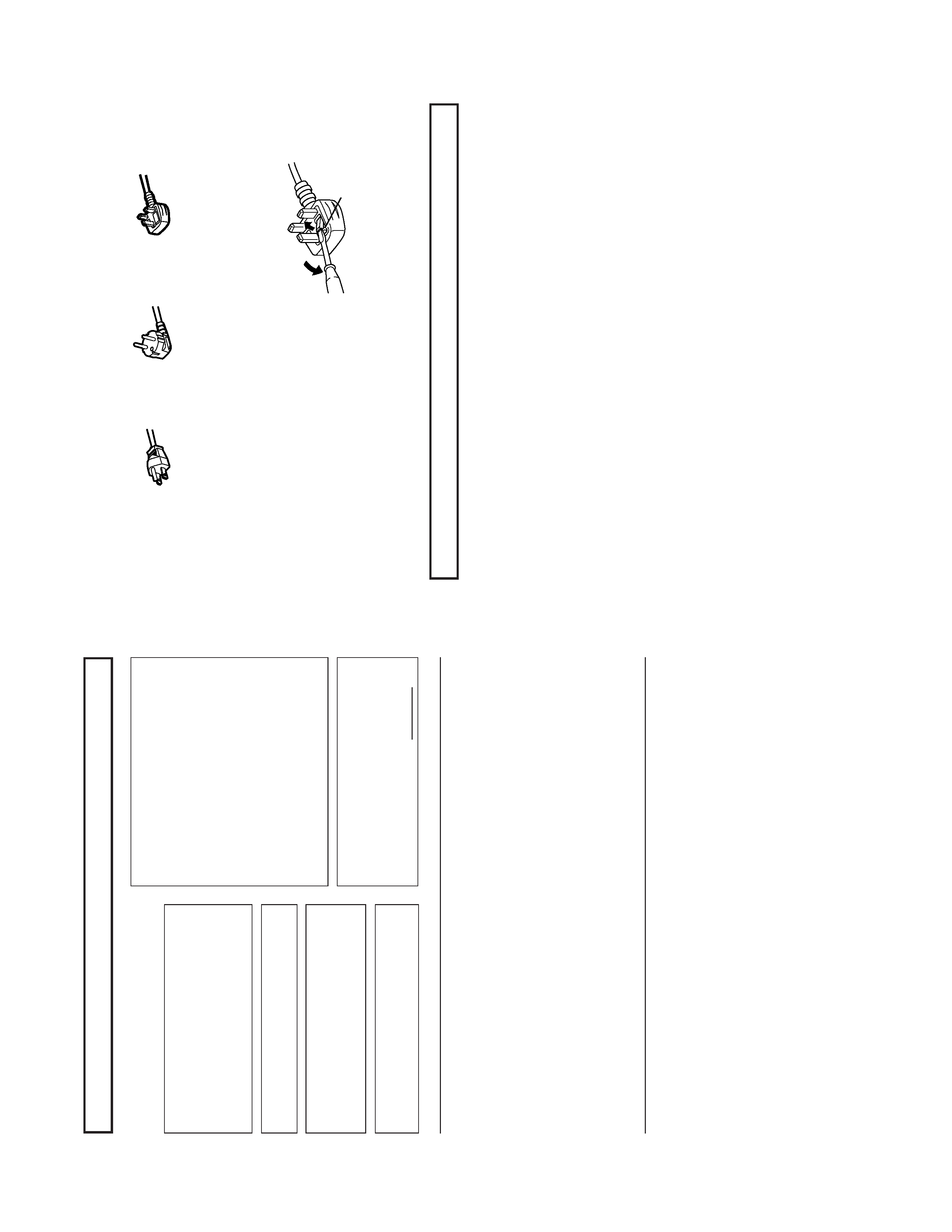
Fuse
POWER
CONNECTION
The
power
supply
voltage
rating
of
this
product
is
AC
120
V
(For
U.S.A.
and
Canada
only)
and
AC
230
V
(For
European
countries
or
United
Kingdom),
the
power
cord
attached
conforms
to
the
following
power
supply
voltage
and
countries.
Use
only
the
power
cord
designated
to
ensure
Safety
and
EMC
regulations
of
each
countries.
Power
cord
Power
supply
voltage
:
AC
120
V
AC
230
V
AC
230
V
Countries
:
U.S.A.
and
Canada
European
countries
United
Kingdom
W
arning:
Do
not
use
the
same
Power
Cord
for
AC
120
V
as
for
AC
230
V
.Doing
so
may
cause
malfunction,
electric
shock
or
fire.
Note
for
the
United
Kingdom
power
cord
only
The
plug
on
the
United
Kingdom
power
cord
has
a
built-in
fuse.
When
replacing
the
fuse,
be
sure
to
use
only
a
correctly
rated
approved
type,
re-fit
the
fuse
cover
.
(Consult
your
dealer
or
qualified
service
personnel.)
How
to
replace
the
fuse
Open
the
fuse
compartment
with
the
blade
screw
driver
,and
replace
the
fuse.
(*
An
example
is
shown
in
the
illustration.)
(No.52097)
DT-V1910CG/E
ENGLISH
1
INSTRUCTIONS
MUL
TI-FORMA
T
MONIT
OR
DT
-V1910CG
Thank
you
for
purchasing
this
JVC
Multi-Format
Monitor
.Before
using
it,
read
and
follow
all
instructions
carefully
to
take
full
advantage
of
the
monitor
's
capabilities.
For
Customer
Use:
Enter
below
the
Serial
No.
which
is
located
on
the
rear
of
the
cabinet.
Retain
this
information
for
future
reference.
Serial
No.
:
Model
No.
:
DT
-V1910CG
SAFETY
PRECAUTIONS
........................................................................
2
CONTROLS
AND
FEA
TURES
................................................................
4
CONTROLS
AND
FEA
TURES
(INPUT
CARD:
OPTIONAL)
..................................................................
7
PREP
ARA
TION
.......................................................................................
9
BASIC
MENU
OPERA
TIONS
(MAIN
MENU,
SETUP
MENU)
............................................................
1
1
HOW
T
O
USE
"MAIN
MENU"
...............................................................
13
HOW
T
O
USE
"SETUP
MENU"
............................................................
16
HOW
T
O
USE
EXTERNAL
CONTROL
.................................................
21
TROUBLESHOOTING
...........................................................................
23
SELF-CHECK
INDICA
TIONS
..............................................................
25
SPECIFICA
TIONS
.................................................................................
26
CONTENTS
DT-V1910CG MULTI-FORMAT MONITOR
VICT
OR
COMP
ANY
OF
J
A
P
AN,
LIMITED
©
2003
VICT
OR
COMP
ANY
OF
J
A
P
AN,
LIMITED
Pr
inted
in
J
apan
0103-MA-UN-VP
(No.52097)
DT-V1910CG/E
2
SCREEN
BURN
It
is
not
recommended
to
keep
a
certain
still
image
displayed
on
screen
for
a
long
time
as
well
as
displaying
extremely
bright
images
on
screen.
This
may
cause
a
burning
(sticking)
phenomenon
on
the
screen
of
cathode-ray
tube.
This
problem
does
not
occur
as
far
as
displaying
normal
video
playback
motion
images.
PRECAUTIONS
Use
only
the
power
source
specified
on
the
unit.
(120
V/230
V
AC,
50
Hz/60
Hz)
Keep
flammable
material,
water
,and
metal
objects
away
from
the
unit
especially
the
interior
of
the
unit.
This
unit
incorporates
high
voltage
circuitry
.
For
your
own
safety
and
that
of
your
equipment,
do
not
attempt
to
modify
or
disassemble
this
monitor
.
There
are
no
user-serviceable
parts
inside.
V
ideo
or
audio
signals
cannot
be
input
to
this
monitor
without
optional
input
cards.
In
these
instructions,
all
explanations
(except
where
noted)
refer
to
the
DT
-V1910CG
with
input
cards
installed.
HANDLING
A
void
shocks
or
vibrations.
These
may
damage
the
unit
and
cause
it
to
malfunction.
Do
not
block
the
ventilation
slots.
Do
not
expose
this
unit
to
high
temperatures.
Extended
exposure
to
direct
sunlight
or
a
heater
could
deform
the
cabinet
or
cause
the
performance
of
internal
components
to
deteriorate.
Do
not
place
the
unit
near
appliances
generating
strong
electric
or
magnetic
fields.
There
can
generate
picture
noise
and
instability
.
Keep
the
monitor
clean
by
wiping
the
cabinet
and
CR
T
screen
with
a
piece
of
soft
cloth.
Do
not
apply
thinner
or
benzine.
These
chemicals
can
damage
the
finish
and
erase
printed
letters.
When
the
unit
is
excessively
dirty
,use
a
diluted
neutral
cleanser
,then
wipe
away
the
cleanser
with
a
dry
cloth.
DEGAUSS
Do
not
use
a
magnet
eraser
to
degauss
the
monitor
's
cathode
ray
tube
from
the
outside.
Doing
so
may
distort
its
aperture
grill
and
cause
a
malfunction.
In
order
to
prevent
any
fatal
accidents
caused
by
misoperation
or
mishandling
the
monitor
,be
fully
aware
of
all
the
following
precautions.
W
ARNINGS
T
o
prevent
fire
or
shock
hazard,
do
not
expose
this
monitor
to
rain
or
moisture.
Dangerous
high
voltages
are
present
inside
the
unit.
Do
not
remove
the
back
cover
of
the
cabinet.
When
servicing
the
monitor
,
consult
qualified
service
personnel.
Never
try
to
service
it
yourself.
W
ARNING
:
THIS
APP
ARA
T
US
MUST
BE
EAR
THED.
Improper
operations,
in
particular
alternation
of
high
voltage
or
changing
the
type
of
tube
may
result
in
x-ray
emission
of
considerable
dose.
A
unit
altered
in
such
a
way
no
longer
meets
the
standards
of
certification,
and
must
therefore
no
longer
be
operated.
This
monitor
is
equipped
with
a
3-blade
grounding-type
plug
to
satisfy
FCC
rule.
If
you
are
unable
to
insert
the
plug
into
the
outlet,
contact
your
electrician.
FCC
NOTICE
(U.S.A.
only)
CAUTION:
Changes
or
modifications
not
approved
by
JVC
could
void
the
user
's
authority
to
operate
the
equipment.
NOTE:
This
equipment
has
been
tested
and
found
to
comply
with
the
limits
for
a
Class
A
digital
device,
pursuant
to
Part
15
of
the
FCC
Rules.
These
limits
are
designed
to
provide
reasonable
protection
against
harmful
interference
when
the
equipment
is
operated
in
a
commercial
environment.
This
equipment
generates,
uses,
and
can
radiate
radio
frequency
energy
and,
if
not
installed
and
used
in
accordance
with
the
instruction
manual,
may
cause
harmful
interference
to
radio
communications.
Operation
of
this
equipment
in
a
residential
area
is
likely
to
cause
harmful
interference
in
which
case
the
user
will
be
required
to
correct
the
interference
at
his
own
expense.
SAFETY
PRECAUTIONS
ENGLISH
3
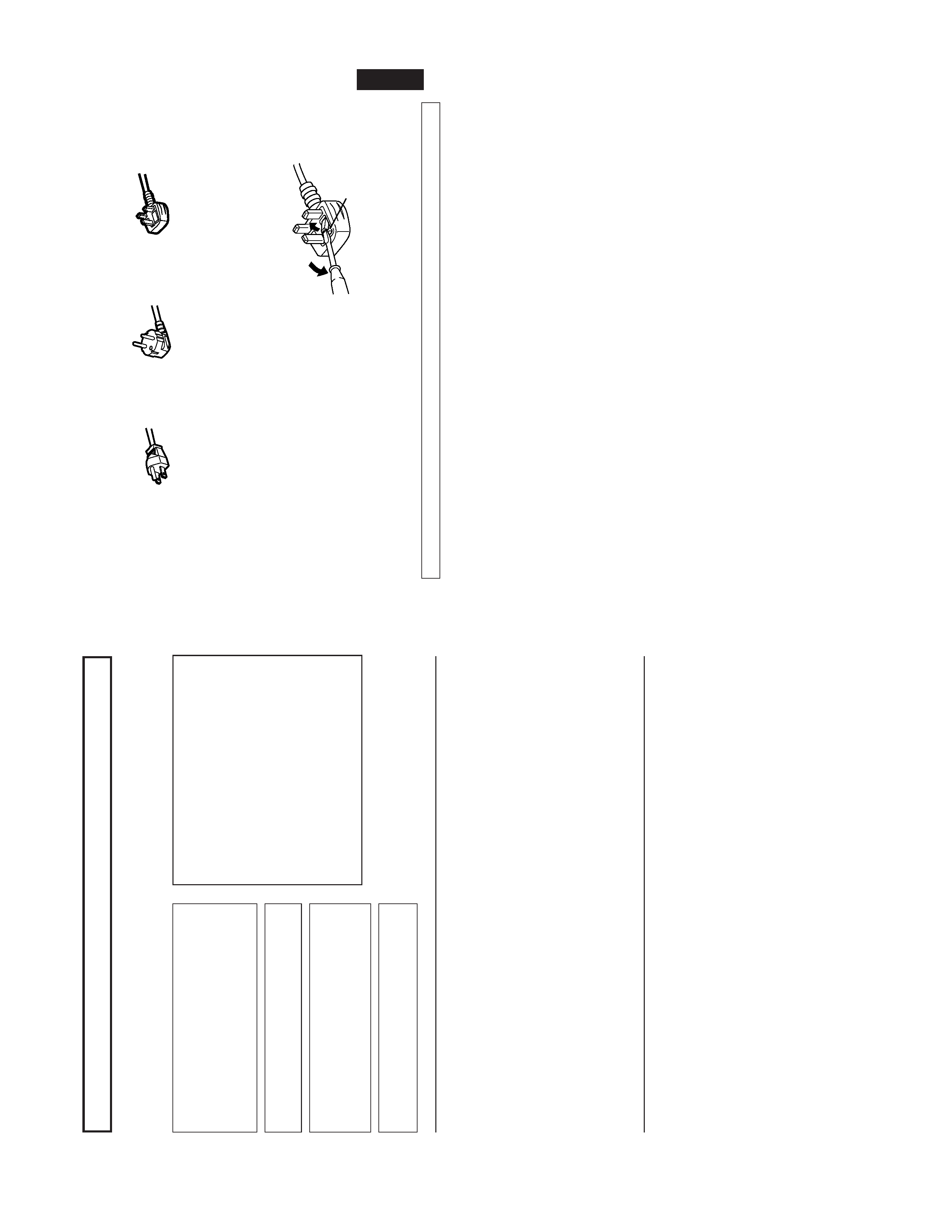
Fuse
EMC
Supplement
(Europe
only)
This
equipment
is
in
conformity
with
the
provisions
and
protection
requirements
of
the
corresponding
European
Directives.
This
equipment
is
designed
for
professional
video
appliances
and
can
be
used
in
the
following
environments:
Controlled
EMC
environment
(for
example
purpose
built
broadcasting
or
recording
studio),
and
the
rural
outdoors
environ-
ment
(far
away
from
railways,
transmitters,
overhead
power
lines,
etc.)
In
order
to
keep
the
best
performance
and
furthermore
for
electromagnetic
compatibility
we
recommend
to
use
cables
not
exceeding
the
following
length:
Cable
Length
Power
cord
(attached
cable)
2.0
m
V
ideo
signal
cable
(coaxial
cable)
2.0
m
Y/C
signal
cable
(shielded
cable)
3.0
m
Audio
signal
cable
(shielded
cable)
1.0
m
D-sub
9-pin
cable
(shielded
cable)
1.5
m
D-sub
15-pin
cable
(shielded
cable)
1.0
m
The
inrush
current
of
this
apparatus
is
20.1
ampere.
Caution
When
in
case
that
the
strong
electromagnetic
waves
or
magnetism
is
near
the
audio
cable
or
the
signal
cable,
the
sound
or
the
picture
will
contain
noise.
In
such
case,
please
keep
the
cable
away
from
the
sources
of
the
disturbance.
POWER
CONNECTION
The
power
supply
voltage
rating
of
this
product
is
AC
120
V
(For
U.S.A.
and
Canada
only)
and
AC
230
V
(For
European
countries
or
United
Kingdom),
the
power
cord
attached
conforms
to
the
following
power
supply
voltage
and
countries.
Use
only
the
power
cord
designated
to
ensure
Safety
and
EMC
regulations
of
each
countries.
Power
cord
Power
supply
voltage
:
AC
120
V
A
C
230
V
AC
230
V
Countries
:
U.S.A.
and
Canada
European
countries
United
Kingdom
W
a
rning:
Do
not
use
the
same
Power
Cord
for
AC
120
V
as
for
AC
230
V
.Doing
so
may
cause
malfunction,
electric
shock
or
fire.
Note
for
the
United
Kingdom
power
cord
only
The
plug
on
the
United
Kingdom
power
cord
has
a
built-in
fuse.
When
replacing
the
fuse,
be
sure
to
use
only
a
correctly
rated
approved
type,
re-fit
the
fuse
cover
.
(Consult
your
dealer
or
qualified
service
personnel.)
How
to
replace
the
fuse
Open
the
fuse
compartment
with
the
blade
screw
driver
,and
replace
the
fuse.
(*
An
example
is
shown
in
the
illustration.)
(No.52097)
DT-V1910CG
4
CONTROLS
AND
FEA
TURES
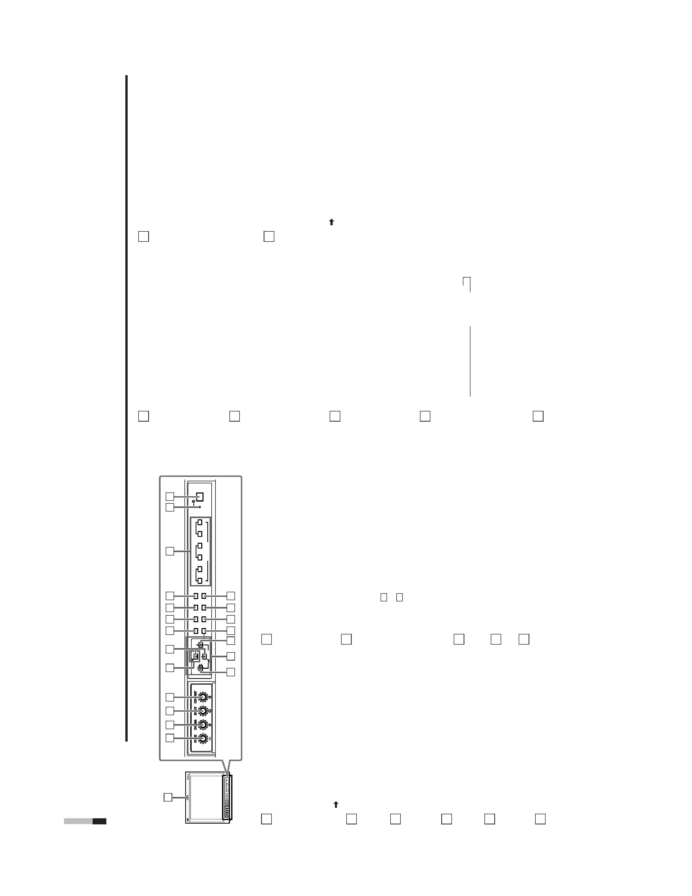
FRONT
VIEW
<Front
Panel>
T
ally
lamp
Lights
when
the
tally
control
signal
is
ON.
·
Set
the
MAKE/TRIGGER
terminal'
s
tally
control
in
the
REMOTE
(external
control)
terminal
setup
menu.
The
lamp
color
can
be
set
to
red
or
green.
·
T
o
set
the
color
,use
T
ALL
Y
SELECT
in
the
"FUNCTION
SETTING"
setup
menu
or
MAKE/TRIGGER
in
the
REMOTE
(external
control)
terminal
setup
menu.
For
details,
refer
to
Page
17
and
21.
PHASE
adjustment
knob
Adjusts
picture
hue.
·
T
urn
the
knob
to
the
left
to
make
the
picture
redder
,and
turn
it
to
the
right
to
make
the
picture
greener
.
CHROMA
adjustment
knob
Adjusts
picture
color
density
.
·
T
urn
the
knob
to
the
left
to
make
the
picture
color
lighter
,and
turn
it
to
the
right
to
make
the
picture
color
deeper
.
BRIGHT
adjustment
knob
Adjusts
picture
brightness.
·
T
urn
the
knob
to
the
left
to
make
the
picture
darker
,and
turn
it
to
the
right
to
make
the
picture
brighter
.
CONTRAST
adjustment
knob
Adjusts
picture
contrast.
·
T
urn
the
knob
to
the
left
to
make
the
picture
contrast
lower
,and
turn
it
to
the
right
to
make
the
picture
contrast
higher
.
VOLUME
buttons
Adjusts
the
speaker
volume.
·
Pressing
this
button
displays
the
VOLUME
level
bar
on
the
screen.
Pressing
the
button
again
allows
you
to
adjust
speaker
volume.
1
10
2
3
4
5
6
9
11
V
OLUME
SLO
T
1
A
B
DEGA
USS
MENU
SCREENS
CHECK
ASPECT
AREA
MARKER
UNDER SCAN
PULSE CR
OSS
COLOR
OFF
SLO
T
2
C
D
SLO
T
3
PO
WER
E
F
INPUT
SELECT
V
O
LUME
SLO
T
1
A
B
DEGA
USS
MENU
MUTING
SCREENS
CHECK
ASPECT
AREA
MARKER
UNDER SCAN
PULSE CR
OSS
COLOR
OFF
SLO
T
2
C
D
SLO
T
3
PO
WER
E
F
INPUT
SELECT
2
3
4
5
8
11
12
13
14
10
9
6
6
15
16
17
18
19
20
1
MUTING
7
8
7
!
!
MUTING
button
Pressing
this
button
mutes
the
output
sound.
·
T
o
cancel
"MUTING
ON"
(no
sound),
press
MUTING
button
again,
or
press
the
VOLUME
""
or
"+"
buttons.
NOTE:
When
a
menu
or
setting
item
(such
as
MAIN
MENU,
SETUP
MENU,
sub-menu,
or
VOLUME
bar)
is
displayed
on
the
screen,
this
button
functions
as
a
control
button
for
the
menu
screen.
In
this
case,
it
will
not
mute
the
sound
when
pressed.
EMBEDDED
AUDIO
channel
switch
button
Press
this
button
while
the
VOLUME
bar
is
displayed
on
the
screen
to
change
the
input
sound
channel.
·
When
the
button
is
pressed,
the
next
highest
channel
is
selected.
·
When
the
button
is
pressed,
the
next
lowest
channel
is
selected.
NOTES:
Switchable
channels
correspond
with
the
group
selected
in
the
"E.AUDIO
GROUP"
of
the
"FUNCTION
SETTING"
setup
menu.
*V
alid
when
an
input
card
compliant
with
EMBEDDED
AUDIO
is
installed.
Menu
select
buttons
Selects
menu
screen
items
or
set-up
menu
screen.
MENU
button
Displays,
adjusts
or
closes
a
menu
screen.
DEGAUSS
button/lamp
Press
the
DEGAUSS
button.
The
button
lights
and
degaussing
is
performed
automatically
.
·
When
the
degaussing
is
completed,
the
light
goes
of
f.
5
13
12
UNDER
SCAN
button/lamp
Press
the
UNDER
SCAN
button.
The
button
lights
and
the
screen
is
reduced
(under-scan)
and
the
whole
screen
is
displayed.
·
When
the
UNDER
SCAN
button
is
pressed
while
lit,
the
light
goes
of
fand
the
screen
returns
to
normal
size
(over-scan).
·
Use
this
function
to
check
the
whole
screen.
NOTE:
This
function
is
invalid
with
the
RGB-input
screen.
PULSE
CROSS
button/lamp
When
you
press
the
PULSE
CROSS
button,
the
button
lights
and
the
picture
moves
horizontally
and
vertically
.
The
synchronized
signal
is
dis-
played
and
the
screen
automatically
brightens
to
make
it
easier
to
confirm
the
synchronized
sections.
·
When
the
PULSE
CROSS
button
is
pressed
while
lit,
the
light
goes
of
fand
the
normal
screen
is
restored.
NOTE:
This
function
is
invalid
with
the
RGB-input
screen.
COLOR
OFF
button/lamp
When
you
press
the
COLOR
OFF
button,
the
button
lights
and
the
screen
becomes
mono-
chrome.
Only
the
brightness
signal
is
displayed.
·
When
the
COLOR
OFF
button
is
pressed
while
lit,
the
light
goes
of
fand
the
normal
screen
is
restored.
·
Use
this
function
to
confirm
the
noise
in
the
brightness
signal
or
to
confirm
the
white
balance.
NOTE:
This
function
is
invalid
with
the
RGB-input
screen.
SCREENS
CHECK
button/lamp
Press
the
SCREENS
CHECK
button.
The
button
lights
and
the
screen
changes
in
the
following
order:
Normal
screen
[
Red
screen
[
Green
screen
Blue
screen
·
Press
the
SCREENS
CHECK
button
when
the
blue
screen
is
displayed.
The
light
goes
of
fand
the
normal
screen
is
restored.
·
Use
this
function
to
confirm
or
adjust
CHROMA
or
PHASE.
NOTE:
This
function
is
invalid
with
the
RGB-input
screen.
ASPECT
button/lamp
When
the
ASPECT
button
is
pressed
while
the
screen
ratio
is
4:3,
the
button
lights
and
the
screen
ratio
changes
to
16:9.
·
When
the
ASPECT
button
is
pressed
while
lit,
the
light
goes
of
fand
the
normal
screen
is
restored.
NOTE:
This
function
is
invalid
with
the
RGB-input
screen.
14
15
16
17
18
[
AREA
MARKER
button/lamp
This
button
turns
the
AREA
MARKER
function
ON/OFF
.
·
AREA
MARKER
function
includes
MARKER,
ZOOM,
and
SAFETY
AREA
functions.
Refer
to
"AREA
MARKER"
on
page
14
for
more
information.
·When
AREA
MARKER
is
set
to
ON,
the
button
lights.
NOTES:
·
Functions
do
not
operate
when
they
are
set
to
OFF
in
the
"AREA
MARKER".
·
Initial
setting
of
each
function
in
the
"AREA
MARKER"
Menu
is
OFF
.
Before
you
can
use
the
AREA
MARKER
function,
you
must
change
the
"AREA
MARKER"
Menu
settings
first.
Refer
to
"AREA
MARKER"
on
page
14
for
details.
·
This
button
does
not
operate
when
RGB
is
input.
·
The
ZOOM
function
does
not
operate
in
the
under-scan
mode.
INPUT
SELECT
button
Selects
an
input
signal
from
one
of
the
input
cards
installed
in
the
monitor
's
card
slots
(SLOT1
SLOT3).
Select
SLOT1:
press
A
or
B
Select
SLOT2:
press
C
or
D
Select
SLOT3:
press
E
or
F
Refer
to
the
input
card
instructions
on
pages
7
and
8
for
details
on
the
correspondence
between
the
input
terminals
and
the
INPUT
SELECT
buttons.
·
The
INPUT
SELECT
button
corresponding
to
the
current
input
signal
lights.
·When
the
input
is
switched,
the
new
input
status
is
displayed
on
the
screen
for
about
3
seconds.
·
T
o
display
the
current
input
status
again,
press
the
illuminated
INPUT
SELECT
.
About
status
display
Displays
information
on
the
current
input
selection
and
the
monitor
settings.
INPUT
C
................
Selected
input
VIDEO
...................
Input
card
status
(*1)
NTSC
....................
Signal
format
(*2)
HIGH
.....................
Setting
of
"COLOR
TEMP
."
(*3)
EXT
SYNC
............
External
synchronization
(*4)
*1
Notes
·"NO
SLOT"
is
displayed
when
there
is
no
input
card
inserted
in
the
slot
corresponding
to
the
selected
input.
·"COMP
."
or
"RGB"
is
displayed
when
a
component
or
RGB
signal
(input
from
COMPONENT/RGB
INPUT
CARD)
is
selected.
·"VIDEO(Y/C)"
is
displayed
when
S-video
is
input
from
VIDEO
2(INPUT
SELECT
B/D/F).
*2
Notes
·"NO
SYNC"
is
displayed
when
no
video
signal
is
input.
·When
"SYNC
SELECT"
is
set
as
"EXT"
(external),
"NO
SYNC"
is
displayed
even
when
a
video
signal
is
input
and
a
synchro-
nized
signal
is
not
input.
Refer
to
"SYNC
SELECT"
on
page
17
for
more
information.
*3
Note
Refer
to
"COLOR
TEMP
."
on
page
18
for
details
on
"COLOR
TEMP"
settings.
*4
Note
When
"SYNC
SELECT"
is
set
to
"INT
."
(internal
synchronization),
no
message
is
displayed.
Refer
to
"SYNC
SELECT"
on
page
17
for
more
information.