SERVICE MANUAL
CD CHANGER SYSTEM
No.49707
Feb. 2002
COPYRIGHT
2002 VICTOR COMPANY OF JAPAN, LTD.
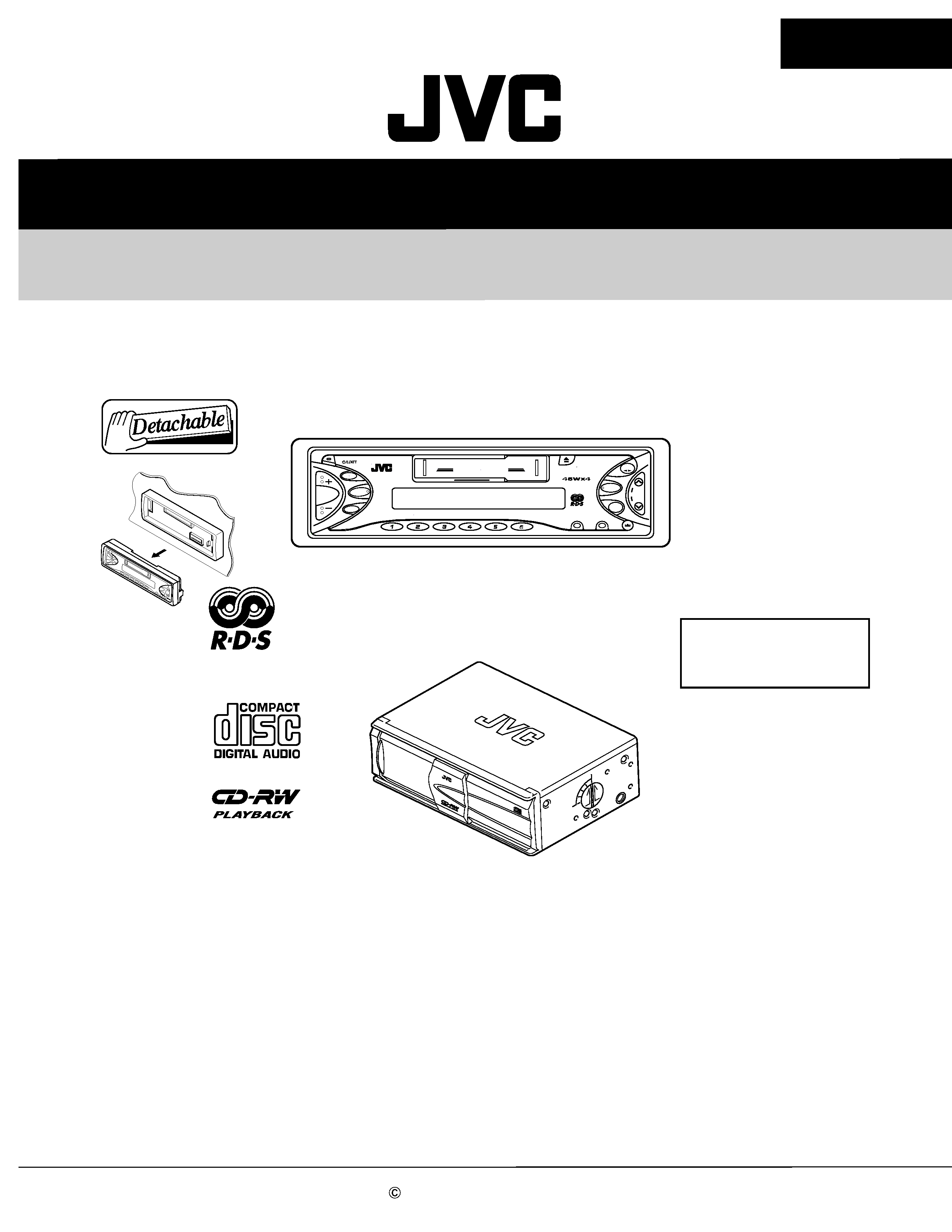
CH-PK772R
CH-PK772R
Area Suffix
KS-FX772R
CD changer control receiver
This model is combination of the CH-X500, CD Changer and the KS-FX772R,
CD changer control receiver in one packing.
Please refer to the service manual of CH-X500(No.49698) and KS-FX772R(No.49694)
for items other than this packing .
CH-X500
CD changer
E ------- Continental Europe
CO
MPA
CT
DIS
C
CHA
NG
ER
12Ð
DIS
C
CH
-X5
00
CD CHANGER CONTROL
SEL
TP/PTY
DISP
SSM
¢
4
FM/AM
TAPE
CD-
CH
DAB
SCM
MODE
7
8
9
10
11
12 RND
RPT
MO
KS-FX772R
CH-PK772R
VICTOR COMPANY OF JAPAN, LIMITED
MOBILE ELECTRONICS DIVISION
PERSONAL & MOBILE NETWORK BUSINESS UNIT. 10-1,1Chome,Ohwatari-machi,Maebashi-city,371-8543,Japan
(No.49707)
200202
Item
Parts number
Parts name
Area
A
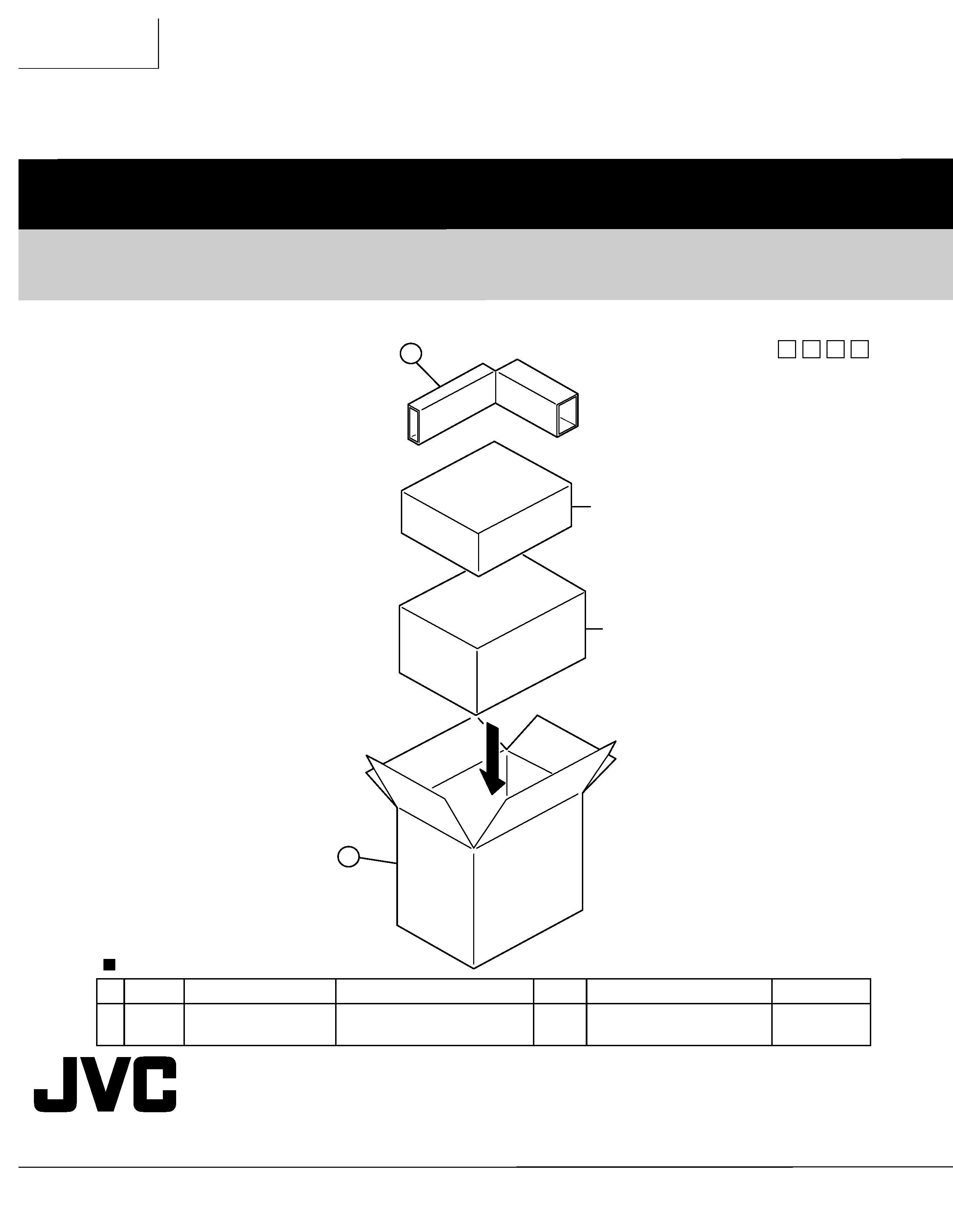
Parts list (Packing)
Q'ty
Description
Block No. M3MM
P 1
LV33460-009A
PACKING CASE
1
P 2
LV33486-001A
SPACER
1
P1
P2
KS-FX772R
CH-X500
Packing materials parts list
Block No. M
M
M
3
SERVICE MANUAL
CASSETTE RECEIVER
No.49694
Mar. 2002
COPYRIGHT
2002 VICTOR COMPANY OF JAPAN, LTD.
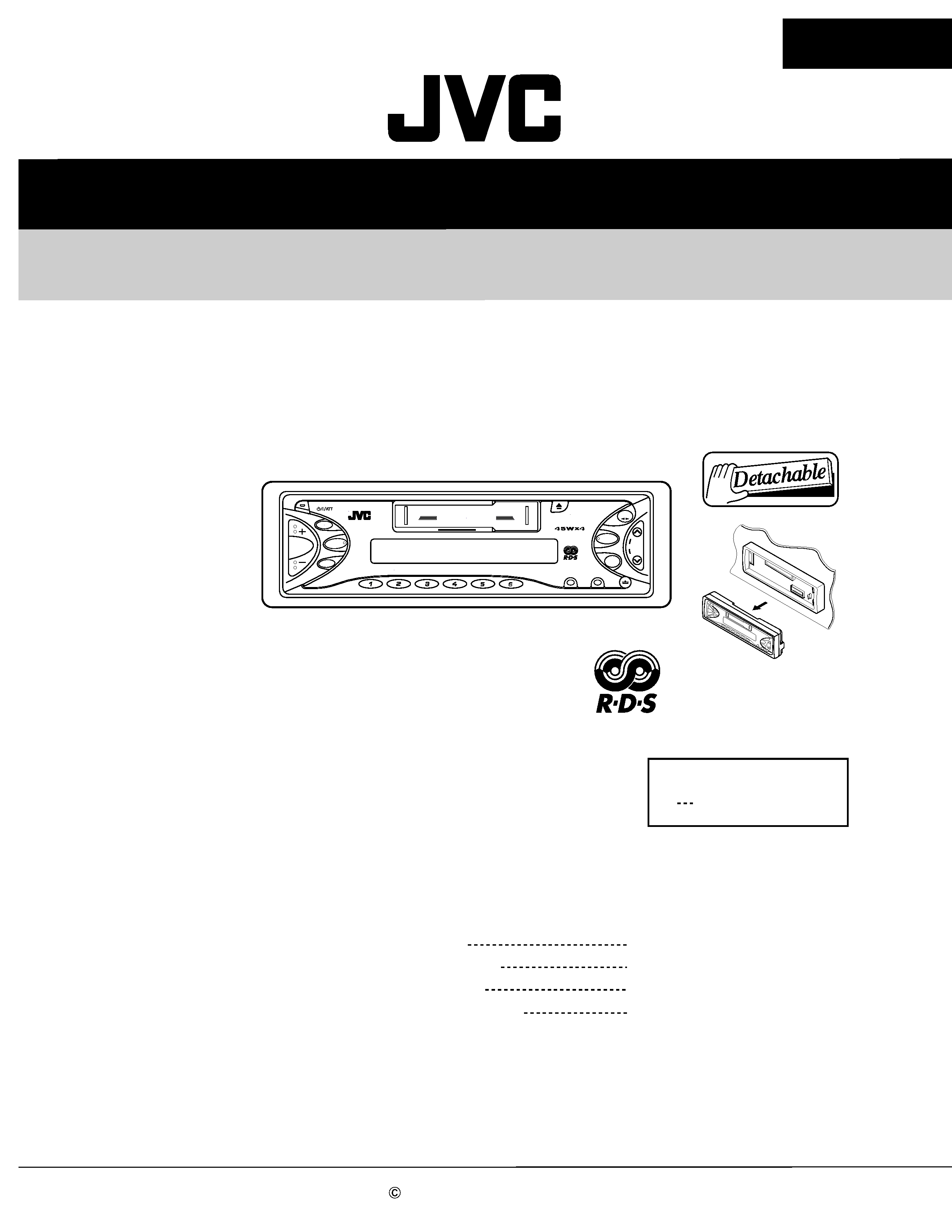
KS-FX772R
KS-FX772R
CD CHANGER CONTROL
SEL
TP/PTY
DISP
SSM
¢
4
FM/AM
TAPE
CD-
CH
DAB
SCM
MODE
7
8
9
10
11
12 RND
RPT
MO
KS-FX772R
Area Suffix
E
Continental Europe
Contents
Safety precaution
Disassembly method
Adjustment method
Description of major ICs
1-2
1-3
1-18
1-22

1-2
KS-FX772R
!
Burrs formed during molding may be left over on some parts of the chassis. Therefore,
pay attention to such burrs in the case of preforming repair of this system.
Safety precaution
1-3
KS-FX772R
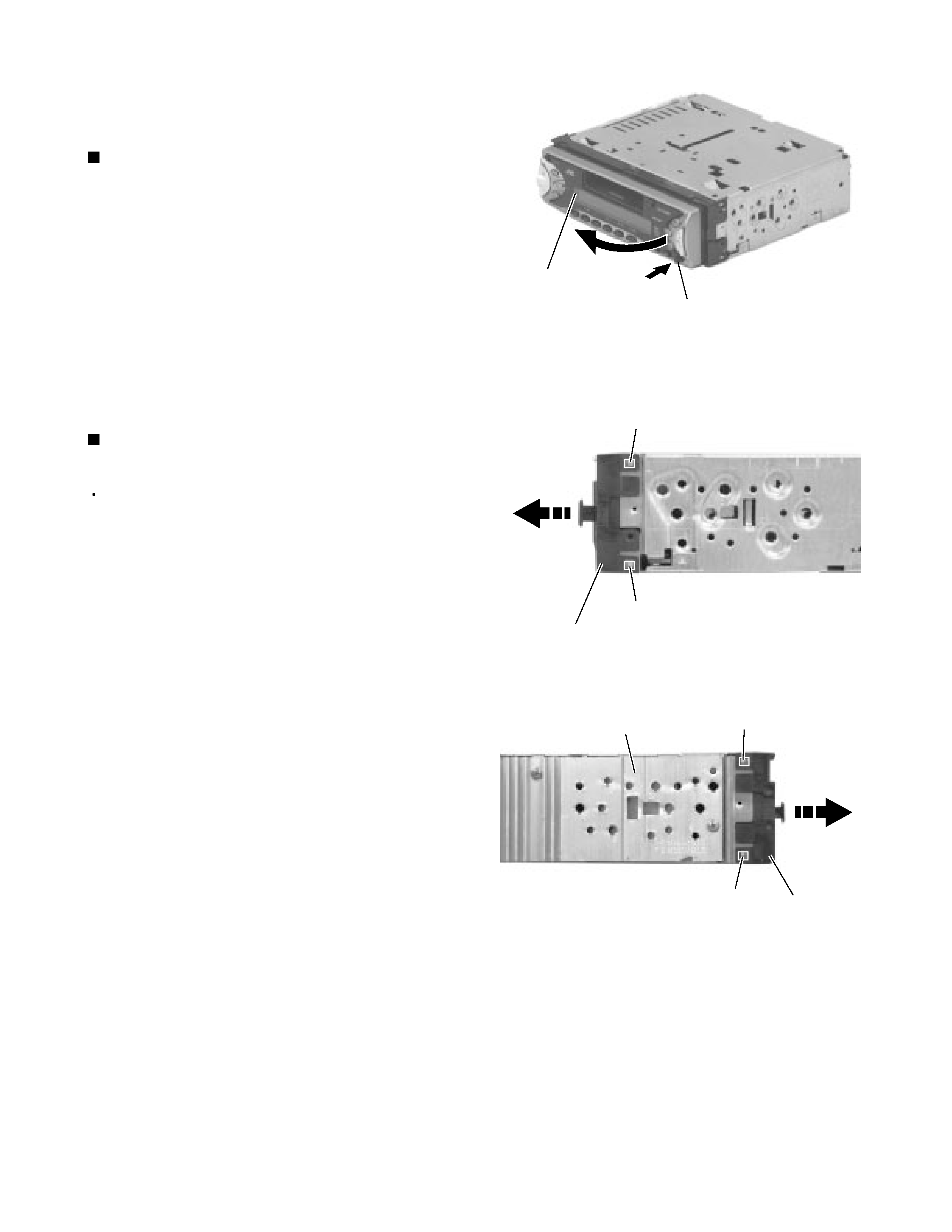
Press the eject button in the lower right part of the
front panel. Remove the front panel assembly from
the body.
1.
Removing the front panel assembly
(See Fig.1)
Prior to performing the following procedure, remove
the front panel assembly.
Release the four joints a on both sides of the front
chassis assembly and remove the front chassis
assembly toward the front.
1.
Removing the front chassis assembly
(See Fig.2 , 3)
Disassembly method
<Main body>
Fig.1
Fig.2
Fig.3
Front panel assembly
Eject button
Joint a
Joint a
Front chassis assembly
Front chassis
assembly
Heat sink
Joint a
Joint a