SERVICE MANUAL
BR-DV3000U/E
DV VIDEO CASSETTE RECORDER
No. 9391
November 2002
COPYRIGHT © 2002 VICTOR COMPANY OF JAPAN, LTD.
Printed in Japan
(S)-I.A/O.S/A.I/GEN
VICTOR COMPANY OF JAPAN, LIMITED
100% recycled paper
BR-DV3000U/E
No.
9391

INSTRUCTIONS
SECTION 1 SERVICE CAUTIONS AND DISASSEMBLY
1.1 CONSTRUCTION OF THE MAIN BOARD ................................ 1-1
1.2 HOW TO REMOVE THE OUTER COVER ................................. 1-2
1.2.1 Top cover ............................................................................ 1-2
1.2.2 Bottom cover ..................................................................... 1-2
1.2.3 Front panel ......................................................................... 1-2
1.3 HOW TO REPLACE THE FUSE ................................................ 1-2
1.4 HOW TO EXAMINE THE BOARDS .......................................... 1-3
1.4.1 MAIN board assembly ....................................................... 1-3
1.4.2 MDA/DC board assembly .................................................. 1-3
1.4.3 DV/CPU board assembly .................................................... 1-3
1.4.4 FRONT board assembly ..................................................... 1-4
1.5 HOW TO REMOVE THE MECHANISM UNIT .......................... 1-4
1.6 HOW TO REMOVE THE MECHANISM ASSEMBLY ................ 1-5
1.7 HOW TO TAKE OUT THE CASSETTE TAPE
IN CASE OF EMERGENCY ................................................ 1-6
1.8 SERVICE MENU ....................................................................... 1-7
1.8.1 Usage procedure ................................................................ 1-7
1.8.2 VTR 1 menu ....................................................................... 1-8
1.8.3 VTR 2 menu ....................................................................... 1-8
1.8.4 VTR 3 menu ....................................................................... 1-9
1.8.5 DIP switch menu ............................................................... 1-9
1.8.6 HOUR METER menu ....................................................... 1-10
1.8.7 ERROR HISTORY menu .................................................. 1-11
1.8.8 OTHERS menu ................................................................. 1-15
1.8.9 CPU version menu ........................................................... 1-16
1.8.10 EEP-ROMS ..................................................................... 1-16
1.8.11 Real-time clock ............................................................... 1-17
SECTION 2 MECHANICAL ADJUSTMENTS
2.1 BEFORE ADJUSTMENTS ........................................................ 2-1
2.1.1 Precautions ........................................................................ 2-1
2.1.2 Measuring instruments required for adjustments ............. 2-1
2.1.3 Equipment required for adjustments ................................. 2-1
2.2 DISASSEMBLY/ASSEMBLY OF THE MECHANISM ................ 2-2
2.2.1 Mechanism position for disassembly/assembly ................ 2-2
2.2.2 Mode transition .................................................................. 2-2
2.3 MECHANISM TIMING CHART ................................................. 2-3
2.4 MAINTENANCE AND INSPECTION OF MAJOR PARTS ........... 2-4
2.4.1 Layout of Major Parts ......................................................... 2-4
2.4.2 Maintenance/inspection table ............................................ 2-5
2.4.3 Cleaning ............................................................................. 2-6
2.4.4 Oiling and Greasing ............................................................ 2-6
2.5 PERIODICAL MAINTENANCE .................................................. 2-7
2.6 REPLACEMENT OF MAJOR PARTS ........................................ 2-8
2.7 GUIDE ROLLER REPLACEMENT METHOD .......................... 2-24
2.8 TORQUE ADJUSTMENT ........................................................ 2-25
2.9 INTERCHANGEABILITY ADJUSTMENT ................................. 2-27
2.9.1 Interchangeabilty adjustment flow chart .......................... 2-27
2.9.2 Tape Transport Restriction ............................................... 2-28
2.9.3 Interchangeability adjustment .......................................... 2-29
SECTION 3 ELECTRICAL ADJUSTMENTS
3.1 PRECAUTIONS FOR ELECTRICAL ADJUSTMENTS ............... 3-1
3.1.1 Measuring instruments and Tools required for
adjustments ....................................................................... 3-1
3.1.2 Alignment tape specifications ............................................ 3-1
3.1.3 Signals required for adjustments ....................................... 3-1
3.1.4 Notes for adjustments ....................................................... 3-2
3.1.5 Adjustment menu .............................................................. 3-2
3.2 DVC UNIT ADJUSTMENTS ...................................................... 3-4
3.3 VIDEO SYSTEM ADJUSTMENTS ............................................ 3-8
3.4 REWRITE BOARD SCHEMATIC DIAGRAM ........................... 3-23
SECTION 4 CHARTS AND DIAGRAMS
4.1 INDEX TO PAGES OF MAIN BOARDS AND
CIRCUIT BOARD LOCATION ................................................... 4-4
4.1.1 Circuit board location ......................................................... 4-4
4.2 SYSTEM CONTROL BLOCK DIAGRAM ................................... 4-5
4.3 VIDEO BLOCK DIAGRAM ........................................................ 4-6
4.4 AUDIO BLOCK DIAGRAM ....................................................... 4-7
4.5 OVERALL WIRING DIAGRAM ................................................. 4-8
4.6 DV UNIT OVERALL WIRING DIAGRAM .................................. 4-9
4.7 MAIN SCHEMATIC DIAGRAM 1/6 ......................................... 4-10
· MAIN SCHEMATIC DIAGRAM 2/6 ......................................... 4-11
· MAIN SCHEMATIC DIAGRAM 3/6 ......................................... 4-12
· MAIN SCHEMATIC DIAGRAM 4/6 ......................................... 4-13
· MAIN SCHEMATIC DIAGRAM 5/6 ......................................... 4-14
· MAIN SCHEMATIC DIAGRAM 6/6 ......................................... 4-15
4.8 MAIN CIRCUIT BOARD .......................................................... 1-16
4.9 DV/CPU SCHEMATIC DIAGRAM 1/4 ..................................... 4-18
· DV/CPU SCHEMATIC DIAGRAM 2/4 ..................................... 4-19
· DV/CPU SCHEMATIC DIAGRAM 3/4 ..................................... 4-20
· DV/CPU SCHEMATIC DIAGRAM 4/4 ..................................... 4-21
4.10 DV/CPU CIRCUIT BOARD ..................................................... 4-22
4.11 MDA/DC CIRCUIT BOARD ................................................... 4-23
4.12 MDA/DC SCHEMATIC DIAGRAM 1/4 ................................... 4-24
· MDA/DC SCHEMATIC DIAGRAM 2/4 ................................... 4-25
· MDA/DC SCHEMATIC DIAGRAM 3/4 ................................... 4-26
· MDA/DC SCHEMATIC DIAGRAM 4/4 ................................... 4-27
4.13 FDM (FRONT, DV, CONN & MIC)
SCHEMATIC DIAGRAM ........................................................ 4-28
4.14 FDM (FRONT, DV, CONN & MIC) CIRCUIT BOARDS ........... 4-29
4.15 MECHA & MECHA CONN SCHEMATIC DIAGRAMS ........... 4-30
4.16 MECHA & MECHA CONN CIRCUIT BOARDS ...................... 4-31
4.17 IC BLOCK DIAGRAMS .......................................................... 4-33
SECTION 5 EXPLODED VIEW AND PARTS LIST
5.1 CABINET & CHASSIS ASSEMBLY
M2 .................................... 5-3
5.2 MECHANISM ASSEMBLY
M3 ................................................ 5-4
SECTION 6 ELECTRICAL PARTS LIST
6.1 MAIN BOARD ASSEMBLY PARTS LIST
01 ........................... 6-2
6.2 FRONT BOARD ASSEMBLY PARTS LIST
02 ....................... 6-11
6.3 DVCONN BOARD ASSEMBLY PARTS LIST
03 ................... 6-11
6.4 MIC BOARD ASSEMBLY PARTS LIST
04 ............................ 6-11
6.5 DV/CPU BOARD ASSEMBLY PARTS LIST
11...................... 6-12
6.6 MDA/DC BOARD ASSEMBLY PARTS LIST
12 .................... 6-15
6.7 MECHA BOARD ASSEMBLY PARTS LIST
13 ..................... 6-18
6.8 MECHA CONN BOARD ASSEMBLY PARTS LIST
14 .......... 6-18
SECTION 7 PACKING
7.1 PACKING ASSEMBLY
M1 ...................................................... 7-1
SECTION 8 TECHNICAL DESCRIPTION
8.1 PRODUCT OUTLINE ................................................................ 8-1
8.2 MECHANISM ........................................................................... 8-1
8.2.1 Comparison with previous mechanism .............................. 8-1
8.2.2 Regarding standard cassette ............................................. 8-1
8.2.3 Cassette housing operation outline ................................... 8-2
8.2.4 Switches ............................................................................ 8-4
8.2.5 Reel motor ......................................................................... 8-4
8.2.6 Tension ............................................................................... 8-4
8.2.7 Mode sensor ...................................................................... 8-5
8.3 SYSTEM CONTROL ................................................................. 8-5
8.3.1 Outline ............................................................................... 8-5
8.3.2 Communication specifications ........................................... 8-5
8.3.3 Communication timing ....................................................... 8-5
8.3.4 SYSCON (IC2001) CPU port functions .............................. 8-6
8.3.5 MSD CPU (IC302) port functions ....................................... 8-8
8.3.6 RS-422A command list .................................................... 8-14
TABLE OF CONTENTS
Section
Title
Page
Section
Title
Page
Important Safety Precautions
Important Safety Precautions
Prior to shipment from the factory, JVC products are strictly inspected to conform with the recognized product safety and electrical codes
of the countries in which they are to be sold. However, in order to maintain such compliance, it is equally important to implement the
following precautions when a set is being serviced.
Fig.1
1. Locations requiring special caution are denoted by labels and
inscriptions on the cabinet, chassis and certain parts of the
product. When performing service, be sure to read and com-
ply with these and other cautionary notices appearing in the
operation and service manuals.
2. Parts identified by the
symbol and shaded (
) parts are
critical for safety.
Replace only with specified part numbers.
Note: Parts in this category also include those specified to com-
ply with X-ray emission standards for products using
cathode ray tubes and those specified for compliance
with various regulations regarding spurious radiation
emission.
3. Fuse replacement caution notice.
Caution for continued protection against fire hazard.
Replace only with same type and rated fuse(s) as specified.
4. Use specified internal wiring. Note especially:
1) Wires covered with PVC tubing
2) Double insulated wires
3) High voltage leads
5. Use specified insulating materials for hazardous live parts.
Note especially:
1) Insulation Tape
3) Spacers
5) Barrier
2) PVC tubing
4) Insulation sheets for transistors
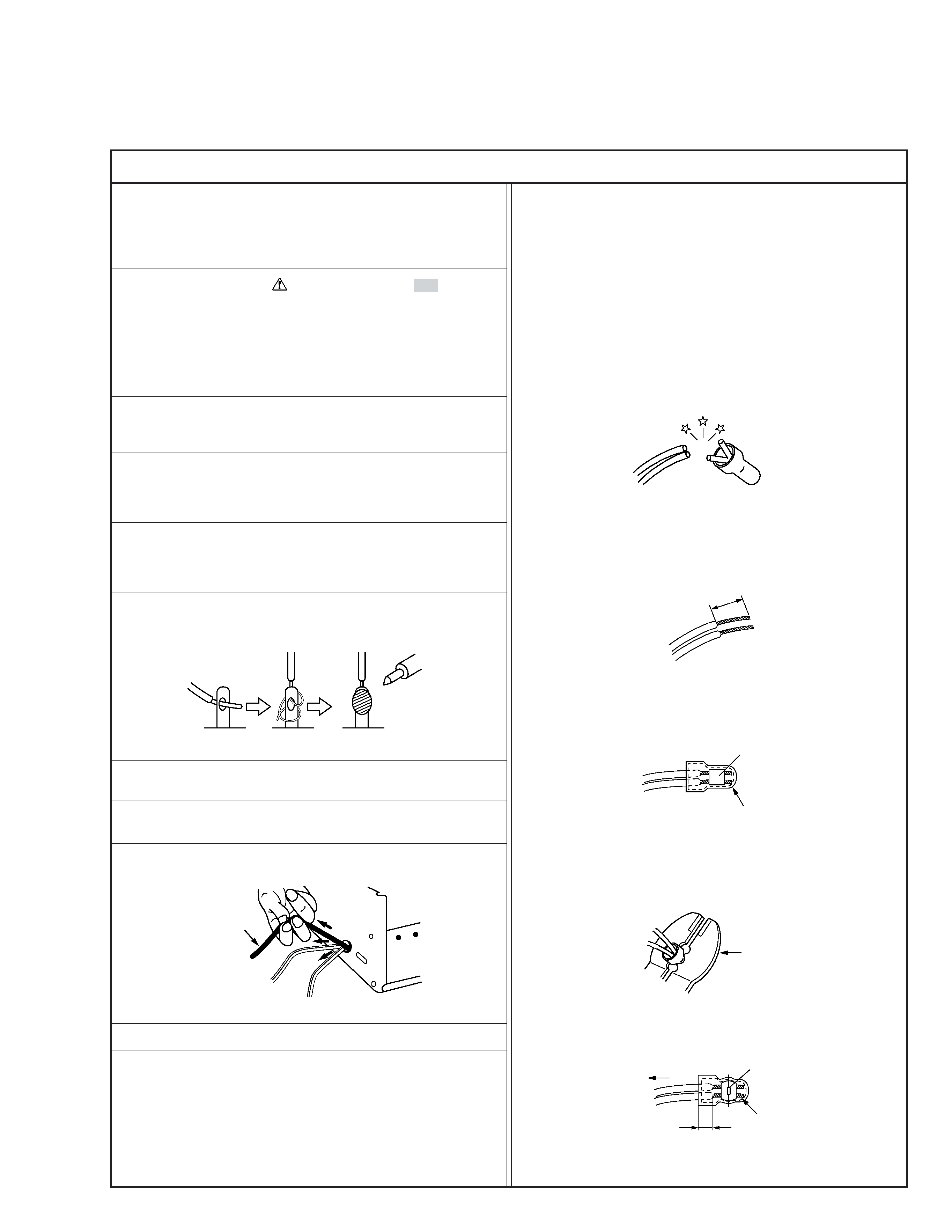
6. When replacing AC primary side components (transformers,
power cords, noise blocking capacitors, etc.) wrap ends of
wires securely about the terminals before soldering.
Power cord
Fig.2
10. Also check areas surrounding repaired locations.
11. Products using cathode ray tubes (CRTs)
In regard to such products, the cathode ray tubes themselves,
the high voltage circuits, and related circuits are specified for
compliance with recognized codes pertaining to X-ray emission.
Consequently, when servicing these products, replace the cath-
ode ray tubes and other parts with only the specified parts.
Under no circumstances attempt to modify these circuits.
Unauthorized modification can increase the high voltage value
and cause X-ray emission from the cathode ray tube.
12. Crimp type wire connector
In such cases as when replacing the power transformer in sets
where the connections between the power cord and power
transformer primary lead wires are performed using crimp type
connectors, if replacing the connectors is unavoidable, in or-
der to prevent safety hazards, perform carefully and precisely
according to the following steps.
1) Connector part number : E03830-001
2) Required tool : Connector crimping tool of the proper type
which will not damage insulated parts.
3) Replacement procedure
(1) Remove the old connector by cutting the wires at a point
close to the connector.
Important : Do not reuse a connector (discard it).
Fig.7
cut close to connector
Fig.3
(2) Strip about 15 mm of the insulation from the ends of
the wires. If the wires are stranded, twist the strands to
avoid frayed conductors.
15 mm
Fig.4
(3) Align the lengths of the wires to be connected. Insert
the wires fully into the connector.
Connector
Metal sleeve
Fig.5
(4) As shown in Fig.6, use the crimping tool to crimp the
metal sleeve at the center position. Be sure to crimp fully
to the complete closure of the tool.
1
Precautions during Servicing
7. Observe that wires do not contact heat producing parts
(heatsinks, oxide metal film resistors, fusible resistors, etc.)
8. Check that replaced wires do not contact sharp edged or
pointed parts.
9. When a power cord has been replaced, check that 10-15 kg of
force in any direction will not loosen it.
1.25
2.0
5.5
Crimping tool
Fig.6
(5) Check the four points noted in Fig.7.
Not easily pulled free
Crimped at approx. center
of metal sleeve
Conductors extended
Wire insulation recessed
more than 4 mm
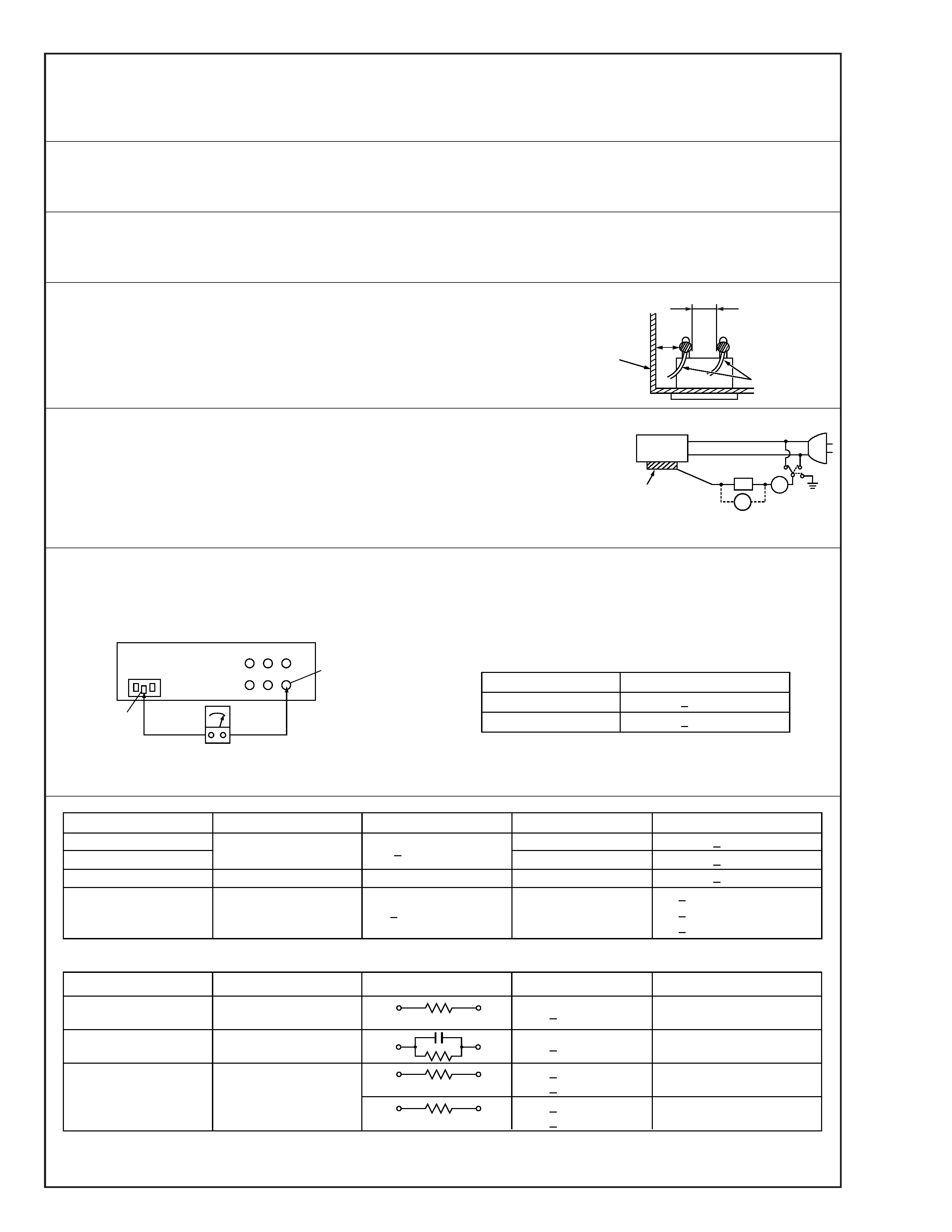
Safety Check after Servicing
Examine the area surrounding the repaired location for damage or deterioration. Observe that screws, parts and wires have been
returned to original positions, Afterwards, perform the following tests and confirm the specified values in order to verify compli-
ance with safety standards.
1. Insulation resistance test
Confirm the specified insulation resistance or greater between power cord plug prongs and
externally exposed parts of the set (RF terminals, antenna terminals, video and audio input
and output terminals, microphone jacks, earphone jacks, etc.). See table 1 below.
2. Dielectric strength test
Confirm specified dielectric strength or greater between power cord plug prongs and exposed
accessible parts of the set (RF terminals, antenna terminals, video and audio input and output
terminals, microphone jacks, earphone jacks, etc.). See table 1 below.
3. Clearance distance
When replacing primary circuit components, confirm specified clearance distance (d), (d') be-
tween soldered terminals, and between terminals and surrounding metallic parts. See table 1
below.
4. Leakage current test
Confirm specified or lower leakage current between earth ground/power cord plug prongs
and externally exposed accessible parts (RF terminals, antenna terminals, video and audio
input and output terminals, microphone jacks, earphone jacks, etc.).
Measuring Method : (Power ON)
Insert load Z between earth ground/power cord plug prongs and externally exposed accessi-
ble parts. Use an AC voltmeter to measure across both terminals of load Z. See figure 9 and
following table 2.
5. Grounding (Class 1 model only)
Confirm specified or lower grounding impedance between earth pin in AC inlet and externally exposed accessible parts (Video in,
Video out, Audio in, Audio out or Fixing screw etc.).
Measuring Method:
Connect milli ohm meter between earth pin in AC inlet and exposed accessible parts. See figure 10 and grounding specifications.
d'
d
Chassis
Power cord,
primary wire
Region
USA & Canada
Europe & Australia
Grounding Impedance (Z)
Z
0.1 ohm
Z
0.5 ohm
AC inlet
Earth pin
Exposed accessible part
Milli ohm meter
Grounding Specifications
Fig. 10
ab
c
V
A
Externally
exposed
accessible part
Z
Fig. 9
Fig. 8
Clearance Distance (d), (d')
d, d'
3 mm
d, d'
4 mm
d, d'
3.2 mm
Dielectric Strength
AC 1 kV 1 minute
AC 1.5 kV 1 miute
AC 900 V 1 minute
AC Line Voltage
100 V
100 to 240 V
110 to 130 V
110 to 130 V
200 to 240 V
Japan
R
1 M/500 V DC
USA & Canada
Europe & Australia
R
10 M/500 V DC
Region
Insulation Resistance (R)
AC 3 kV 1 minute
(Class
2)
AC 1.5 kV 1 minute
(Class
1)
d
4 mm
d'
8 mm (Power cord)
d'
6 mm (Primary wire)
Table 1 Specifications for each region
a, b, c
Leakage Current (i)
AC Line Voltage
100 V
110 to 130 V
110 to 130 V
220 to 240 V
Japan
USA & Canada
i1 mA rms
Exposed accessible parts
Exposed accessible parts
Antenna earth terminals
Other terminals
i
0.5 mA rms
i
0.7 mA peak
i2 mA dc
i
0.7 mA peak
i2 mA dc
Europe & Australia
Region
Load Z
1 k
2 k
1.5 k
0.15 µF
50 k
Table 2 Leakage current specifications for each region
Note: These tables are unofficial and for reference only. Be sure to confirm the precise values for your particular country and locality.
2
1-1
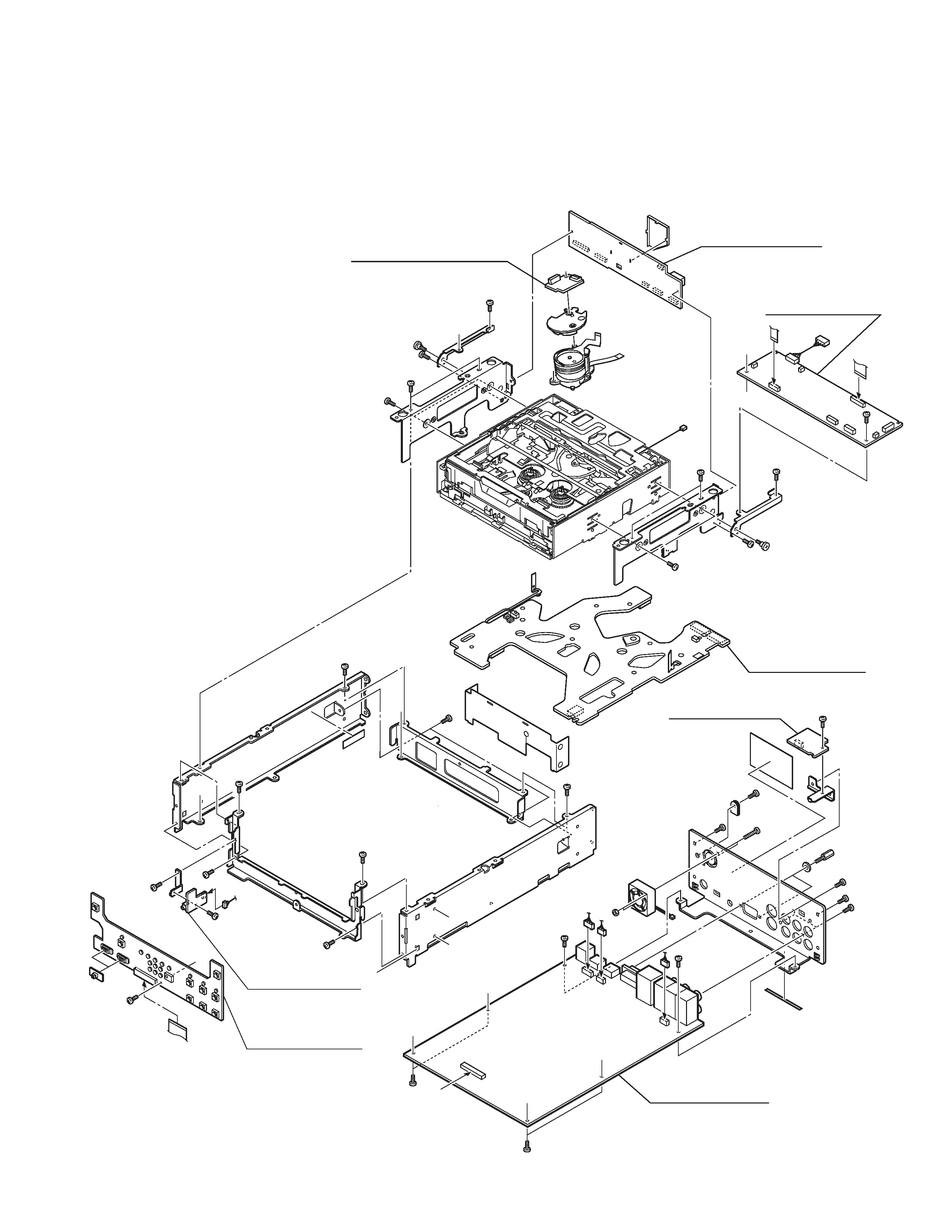
SECTION 1
SERVICE CAUTIONS AND DISASSEMBLY
1.1
CONSTRUCTION OF THE MAIN BOARD
MECHA BOARD
ASSEMBLY
13
MAIN BOARD
ASSEMBLY
01
DV CONN BOARD
ASSEMBLY
03
01 MAIN BOARD ASSEMBLY
02 FRONT BOARD ASSEMBLY
03 DV CONN BOARD ASSEMBLY
04 MIC BOARD ASSEMBLY
11 DV/CPU BOARD ASSEMBLY
12 MDA/DC BOARD ASSEMBLY
13 MECHA BOARD ASSEMBLY
14 MECHA CONN BOARD ASSEMBLY
d
FRONT BOARD
ASSEMBLY
02
MIC BOARD
ASSEMBLY
04 a
f
b
c
d
f
CN4001
DV/CPU BOARD
ASSEMBLY
11
MDA/DC BOARD
ASSEMBLY
12
e
e
MECHA CONN BOARD
ASSEMBLY
14