VICTOR COMPANY OF JAPAN, LIMITED
Printed in Japan
SL96197-002
BR-D95U
VIDEO
CASSETTE
RECORDER
R
is a registered trademark owned by VICTOR COMPANY OF JAPAN, LTD.
is a registered trademark in Japan, the U.S.A., the U.K. and many other countries.
© 2002 VICTOR COMPANY OF JAPAN, LIMITED
INSTRUCTIONS
For Customer Use:
Enter below the Serial No. which is
located on the rear of cabinet. Retain
this information for future reference.
Model No. BR-D95U
Serial No.
VIDEO CASSETTE RECORDER
BR-D95U
R
INTRODUCTION
CONTROLS,
CONNECTORS
AND DISPLAY
CONNECTIONS
MENU SWITCH
SETTING
MENU SWITCH
SETTING
DETAILS
PREPARATION
RECORDING
PLAYBACK
EDITING
OTHER
FUNCTIONS
HOW TO USE
TIME CODE
RS-232C
PROTOCOL
EDITING SYSTEM
PHASE
ADJUSTMENT
TROUBLE-
SHOOTING
SPECIFICA -
TIONS
APPENDIX
COMPONENT DIGITAL
POWER
ON
I
OFF
O
M
H
F
S
REC
MENU
PLAY
PAUSE/STILL
REW
STOP
FF
EJECT
PHONES
CH1
CH2
CH3
CH4
REC
PLAY
PULL FOR VARIABLE
TRACKING
CH1
CH1
CH2
CH3
CH4/
TRACKING
SET
HOLD
PB
PB/EE
COUNTER
UB
CONDITION
AUDIO
INPUT
VIDEO
INPUT
AUDIO
MONITOR
PULL
RELEASE
RESET
VCON
REMOTE
TOP
VIDEO
AUDIO
OTHERS
ON SCREEN
TIME CODE
SERVO/SYS
USER
INSERT
STAND BY
PLAYER
SEARCH
VAR
P.PLAY
DA3
DA2
DA1
VIDEO
ASSEM
IN
ENTRY
OUT
CANCEL
SHIFT
REVIEW
METER MODE
TRACKING
FINE
PREVIEW
AUTO EDIT
PREROLL
TC
RECORDER
DA4
VIDEO CASSETTE RECORDER
BR-D95U
STILL
X-1
REV
FWD
X1
CH2
CH3
CH4
CH1
CH2
CH3
CH4
CH1
CH2
CH3
CH4
SIF
SDI
AES/EBU
AUDIO INPUT / AUDIO MONITOR SELECT
LINE
CPN
L
ANALOG
R
PULL
RELEASE
CTL
P.READ
AUTO OFF
V.VAR
REMOTE
PB/EE
16:9
TC UB DF SERVO
GEN
CF
AP
525
OVER
60
2
4
+2
+4
0
40
30
20
10
0
dB
dB
R
P
OVER
60
2
4
+2
+4
0
40
30
20
10
0
dB
dB
R
P
OVER
60
2
4
+2
+4
0
40
30
20
10
0
dB
dB
R
P
OVER
60
2
4
+2
+4
0
40
30
20
10
0
dB
dB
R
P
625
Variable Motion
COMPONENT DIGITAL
· This manual provides instructions in English and
German.
English : pp. 2 to 151
German: pp. 154 to 174
· To maintain picture and sound quality, use the
exclusive head cleaning cassette after every 20
hours of operation.
For details on head cleaning, refer to page 11.
SL96197-002
This instruction book is made from 100% recycled paper.
This section of instruction manual is specially edited for service
purpose with modified contents.
It is not recommended to use, this section for the substitution of
the original book in the merchandise.
CAUTION
2
1. Read all of these instructions.
2. Save these instructions for later use.
3. All warnings on the product and in the operating instructions should be adhered to.
4. Unplug this appliance system from the wall outlet before cleaning. Do not use liquid cleaners or aerosol cleaners. Use a
damp cloth for cleaning.
5. Do not use attachments not recommended by the appliance manufacturer as they may cause hazards.
6. Do not use this appliance near water for example, near a bathtub, washbowl, kitchen sink, or laundry tub, in a wet
basement, or near a swimming pool, etc.
7. Do not place this appliance on an unstable cart, stand, or table. The appliance may fall, causing
serious injury to a child or adult, and serious damage to the appliance.
Use only with a cart or stand recommended by the manufacturer, or sold with the appliance.
Wall or shelf mounting should follow the manufacturer's instructions, and should use a mounting kit
approved by the manufacturer.
An appliance and cart combination should be moved with care. Quick stops, excessive force, and
uneven surfaces may cause the appliance and cart combination to overturn.
8. Slots and openings in the cabinet and the back or bottom are provided for ventilation, and to insure
reliable operation of the appliance and to protect it from overheating, these openings must not be
blocked or covered. The openings should never be blocked by placing the appliance on a bed, sofa, rug, or other similar
surface. This appliance should never be placed near or over a radiator or heat register. This appliance should not be placed
in a built-in installation such as a bookcase unless proper ventilation is provided.
9. This appliance should be operated only from the type of power source indicated on the marking label. If you are not sure of
the type of power supplied to your home, consult your dealer or local power company. For appliance designed to operate
from battery power, refer to the operating instructions.
10. This appliance system is equipped with a 3-wire grounding type plug (a plug having a third (grounding) pin). This plug will
only fit into a grounding-type power outlet. This is a safety feature. If you are unable to insert the plug into the outlet, contact
your electrician to replace your obsolete outlet. Do not defeat the safety purpose of the grounding plug.
11. For added protection for this product during a lightning storm, or when it is left unattended and unused for long periods of
time, unplug it from the wall outlet and disconnect the antenna or cable system. This will prevent damage to the product due
to lightning and power-line surges.
12. Do not allow anything to rest on the power cord. Do not locate this appliance where the cord will be abused by persons
walking on it.
13. Follow all warnings and instructions marked on the appliance.
14. Do not overload wall outlets and extension cords as this can result in fire or electric shock.
15. Never push objects of any kind into this appliance through cabinet slots as they may touch dangerous voltage points or short
out parts that could result in a fire or electric shock. Never spill liquid of any kind on the appliance.
16. Do not attempt to service this appliance yourself as opening or removing covers may expose you to dangerous voltage or
other hazards. Refer all servicing to qualified service personnel.
17. Unplug this appliance from the wall outlet and refer servicing to qualified service personnel under the following conditions:
a. When the power cord or plug is damaged or frayed.
b. If liquid has been spilled into the appliance.
c. If the appliance has been exposed to rain or water.
d. If the appliance does not operate normally by following the operating instructions. Adjust only those controls that are
covered by the operating instructions as improper adjustment of other controls may result in damage and will often
require extensive work by a qualified technician to restore the appliance to normal operation.
e. If the appliance has been dropped or the cabinet has been damaged.
f. When the appliance exhibits a distinct change in performance this indicates a need for service.
18. When replacement parts are required, be sure the service technician has used replacement parts specified by the manufac-
turer that have the same characteristics as the original part. Unauthorized substitutions may result in fire, electric shock, or
other hazards.
19. Upon completion of any service or repairs to this appliance, ask the service technician to perform routine safety checks to
determine that the appliance is in safe operating condition.
IMPORTANT SAFEGUARDS
3
SAFETY PRECAUTIONS ( FOR USA AND CANADA )
CAUTION
ATTENTION
RISK OF ELECTRIC SHOCK
DO NOT OPEN
RISQUE D'ELECTROCUTION
NE PAS OUVRIR
Le symbole de l'éclair à l'intérieur d'un triangle
équilatéral est destiné à alerter l'utilisateur sur la
présence d'une "tension dangereuse" non isolée
dans le boîtier du produit. Cette tension est suffisante
pour provoquer l'électrocution de personnes.
Le point d'exclamation à l'intérieur d'un triangle
équilatéral est destiné à alerter l'utilisateur sur la
présence d'opérations d'entretien importantes au
sujet desquelles des renseignements se trouvent
dans le manuel d'instructions.
*Ces symboles ne sont utilisés qu'aux Etats-Unis.
NOTE:
The rating plate (serial number plate) is on the rear of the unit.
AVERTISSEMENT:
POUR EVITER LES RISQUES D'INCENDIE OU
D'ELECTROCUTION, NE PAS EXPOSER
L'APPAREIL A L'HUMIDITE OU A LA PLUIE.
Ce magnétoscope ne doit être utilisé que sur du
courant alternatif en 120 V.
ATTENTION:
Afin d'éviter tout resque d'incendie ou
d'électrocution, ne pas utiliser d'autres sources
d'alimentation électrique.
ATTENTION: POUR EVITER TOUT RISQUE D'ELECTROCUTION
NE PAS OUVRIR LE BOITER.
AUCUNE PIECE INTERIEURE N'EST
A REGLER PAR L'UTILISATEUR.
SE REFERER A UN AGENT QUALIFIE EN CAS DE PROBLEME.
CAUTION: TO REDUCE THE RISK OF ELECTRIC SHOCK,
DO NOT REMOVE COVER (OR BACK).
NO USER-SERVICEABLE PARTS INDIDE.
REFER SERVICING TO QUALIFIED SERVICE PERSONNEL
WARNING:
TO REDUCE THE RISK OF FIRE OR ELECTRIC
SHOCK, DO NOT EXPOSE THIS APPLIANCE
TO RAIN OR MOISTURE.
This unit should be used with 120 V AC only.
CAUTION:
To prevent electric shocks and fire hazards, do NOT
use any other power source.
The lightning flash with arrowhead symbol, within an
equilateral triangle, is intended to alert the user to the
presence of uninsulated "dangerous voltage" within
the product's enclosure that may be of sufficient
magnitude to constitute a risk of electric shock to
persons.
The exclamation point within an equilateral triangle is
intended to alert the user to the presence of important
operating and maintenance (servicing) instructions in
the literature accompanying the appliance.
Cet appareil numérique de la classe A respecte toutes les
exigences du Reglement sur le matériel brouilleur du Canada.
REMARQUE:
La plaque d'identification (numéro de série) se trouve sur le
panneau arrière de l'appareil.
INFORMATION
This equipment has been tested and found to comply with the
limits for a Class A digital device, pursuant to Part 15 of the
FCC Rules. These limits are designed to provide reasonable
protection against harmful interference when the eqipment is
operated in a commercial environment. This equipment
generates, uses, and can radiate radio frequency energy and, if
not installed and used in accordance with the instruction
manual, may cause harmful interference to radio communica-
tions.
Operation of this eqipment in a residential area is likely to
cause harmful interference in which case the user will be
required to correct the interference at his own expense.
CAUTION
CHANGES OR MODIFICATIONS NOT APPROVED BY JVC
COULD VOID USER'S AUTHORITY TO OPERATE THE
EQUIPMENT.
This Class A digital apparatus meets all requirements of the
canadian Interference-Causing Eqipment Regulations.
4
SAFETY PRECAUTIONS ( FOR EUROPE AND AUSTRALIA )
Warning Notice
FOR YOUR SAFETY (Australia)
1. Insert this plug only into effectively earthed three-
pin power outlet.
2. If any doubt exists regarding the earthing, consult
a qualified electrician.
3. Extension cord, if used, must be three-core correctly
wired.
IMPORTANT (In the United Kingdom)
Mains Supply (AC 230 V `)
WARNING THIS APPARATUS
MUST BE EARTHED
The wires in this mains lead are coloured in
accordance with the following code;
GREEN-and-YELLOW: EARTH
BLUE
: NEUTRAL
BROWN
: LIVE
As the colours of the wires in the mains lead of this
apparatus may not correspond with the coloured
markings identifying the terminals in your plug, proceed
as follows.
The wire which is coloured GREEN-AND-YELLOW
must be connected to the terminal in the plug which is
marked with the letter E or by the safety earth symbol
or coloured GREEN or GREEN-AND-YELLOW. The
wire which is coloured BLUE must be connected to the
terminal which is marked with the letter N or which is
coloured BLACK. The wire which is coloured BROWN
must be connected to the terminal which is marked with
the letter L or coloured RED.
POWER SYSTEM
Connection to the mains supply
This unit operates on voltage of 110 V to 240 V AC,
50 Hz/60 Hz.
WARNING:
TO REDUCE THE RISK OF FIRE OR ELECTRIC
SHOCK, DO NOT EXPOSE THIS APPLIANCE TO
RAIN OR MOISTURE.
CAUTION
To prevent electric shock, do not open the cabinet. No
user serviceable parts inside.
Refer servicing to
qualified service personnel.
WARNING
This is a Class A product. In a domestic environment
this product may cause radio interference in which
case the user may be required to take adequate
measures.
Note:
The rating plate and the safety caution are on the rear
of the unit.
WARNING
It should be noted that it may be unlawful to re-record
pre-recorded tapes, records, or discs without the
consent of the owner of copyright in the sound or video
recording, broadcast, or cable programme and in any
literary, dramatic, musical or artistic work embodied
therein.
CAUTION
RED colour indications on the operation panel are
provided but they are not safety related.
RED colour indications:
(1) For Cassette Recording Button
(2) For Level Over Audio In/Out Indicator
(3) For Tape Error Indicator
This apparatus is designed in compliance with ISO
7779/1999 (Acoustics -- Measurement of airborne
noise emmited by information technology telecom-
munications equipment), whose acoustic noise is
less than 70 dB.
5
This equipment is in conformity with the provisions and protection requirements of the corresponding European
Directives. This equipment is designed for professional video appliances and can be used in the following
environments:
Controlled EMC environment (for example purpose built broadcasting or recording studio), and the rural
outdoors environment (far away from railways, transmitters, overhead power lines, etc.)
In order to keep the best performance and furthermore for electromagnetic compatibility we recommend to use
cables not exceeding the following length:
Port
Cable
Length
AC INPUT
Power supply cord
2.5 meters
SERIAL V/A IN
Coaxial cable
10 meters
SERIAL V/A OUT
Coaxial cable
10 meters
AES/EBU IN, OUT
Coaxial cable
10 meters
RS-232C
Shielded cable
3 meters
REMOTE
Exclusive cable
5 meters
VIDEO CONTROL
Exclusive cable
5 meters
COMPOSITE IN, OUT
Coaxial cable
10 meters
REF IN
Coaxial cable
10 meters
Y/R-Y/B-Y IN, OUT
Coaxial cable
10 meters
TIME CODE IN, OUT
Coaxial cable
10 meters
AUDIO IN CH1, CH2
Shielded twist pair cable
10 meters
AUDIO OUT CH1, CH2
Shielded twist pair cable
10 meters
AUDIO MONITOR
Shielded cable
10 meters
PHONES
Cable with headphones
3 meters
The inrush current of this apparatus is 17 amperes.
Caution
When in case that the strong electromagnetic waves or magnetism is near the audio in ch1, ch2 cable, the sound
will contain noise.
In such case, please keep the cable away from the disturbance.
6
MAIN FEATURES
Do not record important material in the first two or
three minutes of a tape.
It may be unlawful to use any material recorded
from TV broadcast programs or pre-recorded
programs without the consent of the owner of
copyright, except in cases where this material is
recorded exclusively for personal use.
JVC is not liable for compensation for loss or
damage to recordings in the event this unit fails to
record or play back properly because the unit
malfunctions or a defective video cassette tape is
used.
This unit is designed for professional use.
CAUTION: 4-channel audio
insert editing
Do not try to perform audio insert
editing on tapes with 4 audio channels
when using a 2-channel audio DIGITAL
S VCR (BR-D85U/E, BR-D80U/E, BR-
D750U/E).
If audio insert editing is executed,
audio signals recorded on DA3 and
DA4 will be erased.
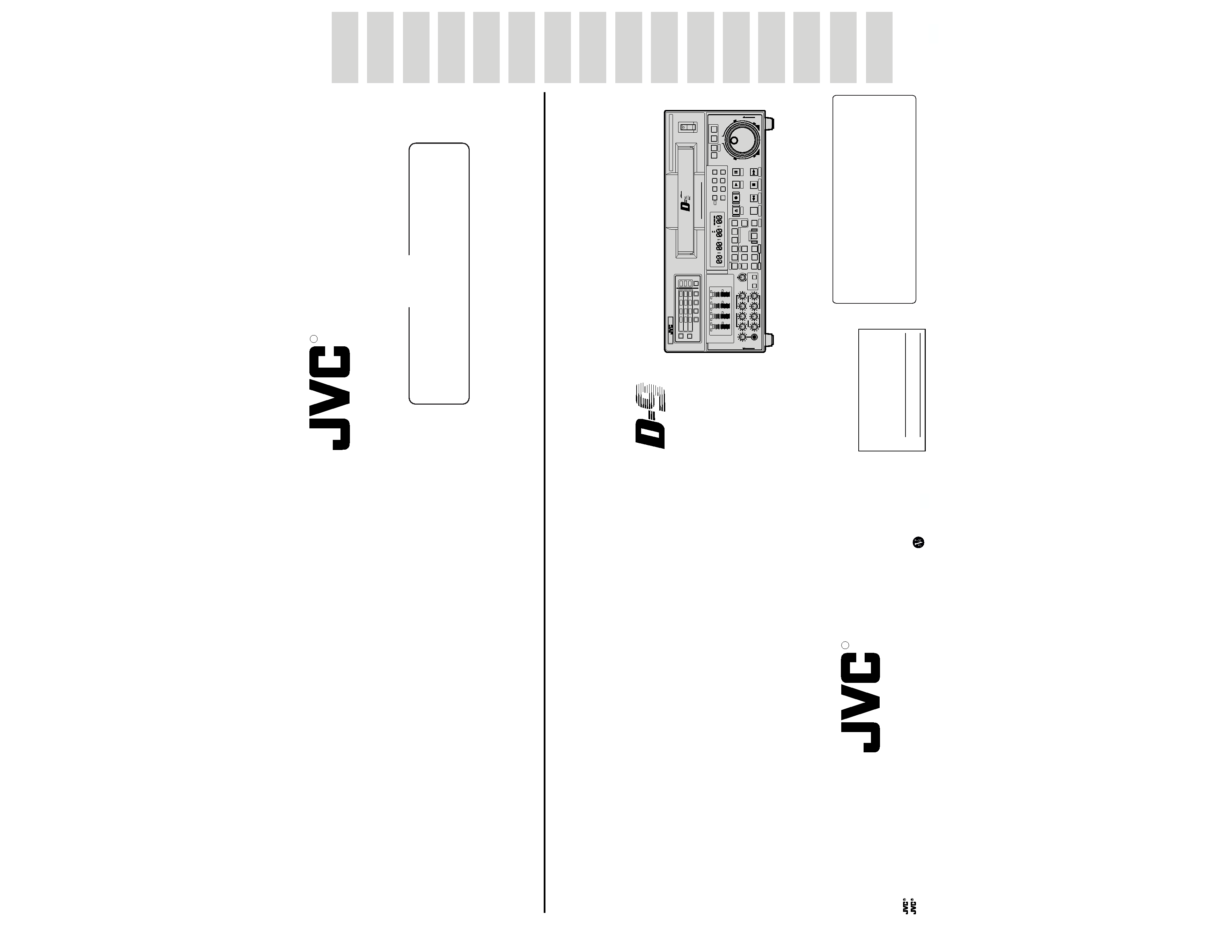
Thank you for purchasing the BR-D95U DIGITAL S
Video Cassette Recorder with electronic editing
capabilities.
This unit can be used with either NTSC or PAL
signal systems. Before using this unit, first select
the signal system.
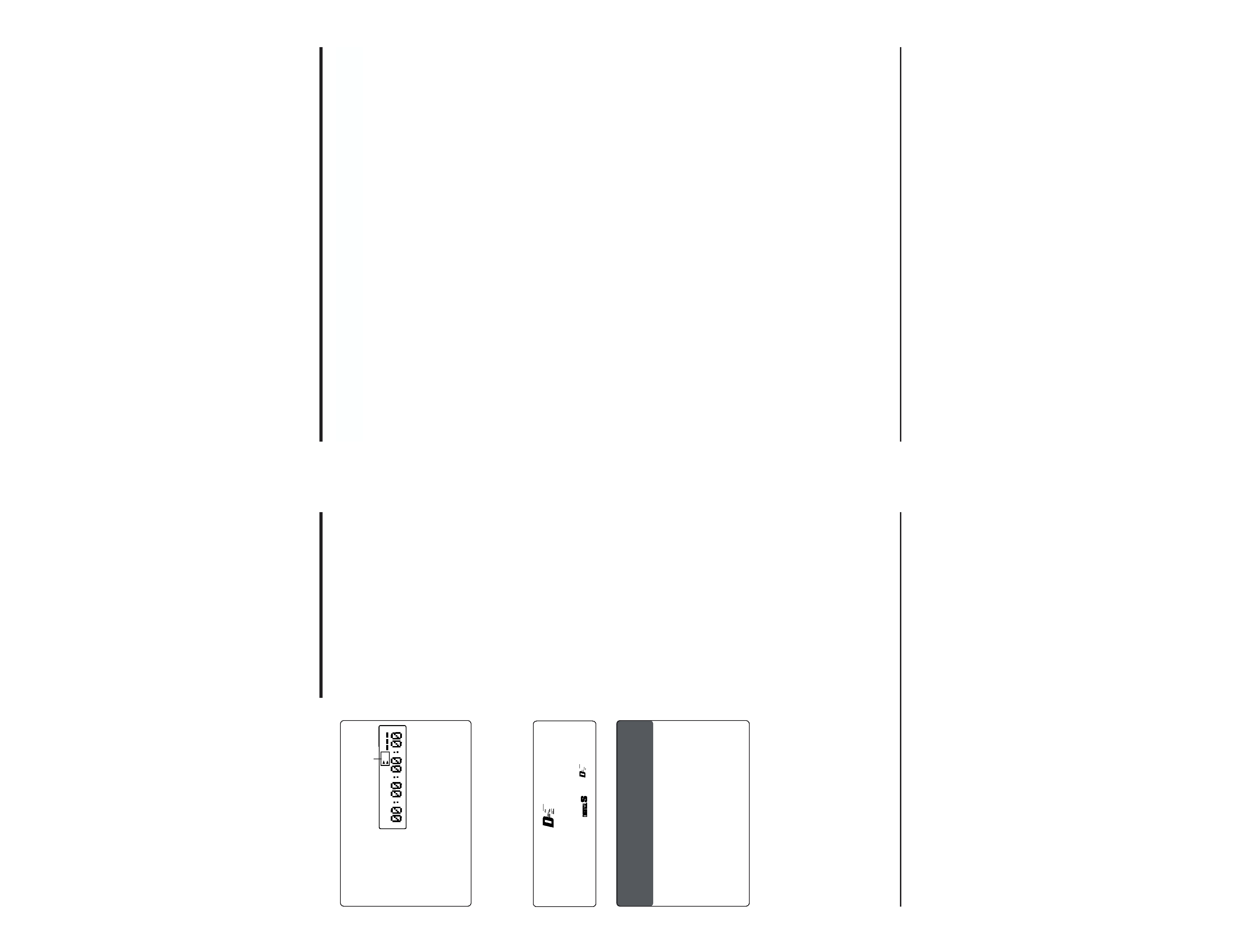
The signal system
you select will be
indicated on the
counter display
with "525" for NTSC
and "625" for PAL. For instructions on how to
select the signal system, refer to "4-2 VIDEO
SIGNAL SYSTEM SELECTION" on page 30.
The optional SA-D95U digital interface board is
required for input/output of serial digital signals.
CONDITION
525
625
Signal system indication
Counter display
Superb picture quality achieved by the DIGITAL S
format using 4:2:2 component digital processing
Independently editable 4-channel PCM high-quality
sound
4-channel PCM high-quality sound with 16-bit 48
kHz sampling. 4-channel audio can be edited
independently.
High-density metal tape based on the W-VHS
format
Built-in time code generator/reader to enable
recording and reading of SMPTE/EBU-Standard
time code and user bits
Pre-read function
This function makes it possible to execute A/B roll
editing using only one player (video/audio insert
only).
Swap editing
The swap control function allows the player VCR to
be controlled from the recorder VCR via 9-pin
remote cable. This allows automatic editing even
when an editing controller is not available.
Audio split editing
Audio edit start points can be set separately with
the video signal edit start point as a reference.
Color frame servo function
This function ensures that continuity of the color
subcarrier phase is maintained during editing.
Audio V fade function
This function fades the audio level during a
transition in V shape to reduce noise.
Complete analog interface with input/output
terminals for composite, color difference component
and analog audio signals included as standard
Internally installable serial digital interface board
optionally available for configuration of fully digital
systems
Jog/search dial
Built-in noiseless slow playback facility for noiseless
playback within a speed range of approximately
1 to +1 normal
Audio monitor facility for search
The D-9 format provides two linear audio channels,
enabling audio monitoring even during video shuttle
search.
Tiltable front panel
Playback audio output adjustment function
Recording audio input adjustment function
Video output adjustment function
Whenever (NTSC) or (525) is specified in this
manual, the accompanying information applies only
to the NTSC signal system. Similarly, information
that is specified as (PAL) or (625) applies only to the
PAL signal system.
This video cassette recorder uses the DIGITAL
S format. It can only be used with video tape
cassettes bearing the "
" or "
COMPONENT DIGITAL
" logo.
COMPONENT DIGITAL
7
CONTENTS
1INTRODUCTION ............................................... 8
1-1 Outline .................................................... 8
1-2 Maintenance ........................................... 9
1-3 Precautions ............................................. 10
1-4 Video Cassette ....................................... 11
1-5 Head Cleaning ........................................ 11
2 CONTROLS, CONNECTORS AND DISPLAYS 12
2-1 Front Panel ............................................. 12
2-2 Sub Panel ............................................... 18
2-3 Rear Panel .............................................. 19
2-4 Counter Display ...................................... 21
2-5 On-screen Display .................................. 23
3 CONNECTIONS ................................................ 25
3-1 Input Connections ................................... 25
3-2 Output Connections ................................ 26
3-3 Control System Connections .................. 27
4 MENU SWITCH SETTING ................................. 28
4-1 Menu Display Modes .............................. 28
4-2 Video Signal System Selection ............... 30
4-3 Menu Switch Setting ............................... 31
4-4 Saving and Calling Up Menu Switch
Settings ................................................... 32
4-5 Calling Up Functional Menu Switch (Direct
Access Function) .................................... 33
4-6 User Page Registration/Change/Delete
(User Page Function) .............................. 34
4-7 How to Lock the Menu Switch Settings ..... 37
4-8 Recording Current Adjustment ............... 38
4-9 Hour Meter Data Display ........................ 39
5 MENU SWITCH SETTING DETAILS ................ 40
5-1 Menu Switch List ..................................... 40
5-2 Menu Switch Setting Content ................. 43
6 PREPARATION ................................................. 65
6-1 Operation Mode Lock ............................. 65
6-2 Standby ON/OFF .................................... 66
6-3 Loading and Unloading the Cassette ...... 67
7 RECORDING ..................................................... 68
7-1 Preparation for Recording ....................... 68
7-2 Input Video and Audio Signal Selection .. 69
7-3 Audio Monitor Output Signal Selection ... 70
7-4 Audio Record level Adjustment ............... 71
7-5 Basic Recording Operations ................... 73
7-6 Digital audio signal input/output .............. 74
8 PLAYBACK ....................................................... 75
8-1 Preparation for Playback ........................ 75
8-2 Basic Playback Operations ..................... 76
8-3 Audio Playback Level Adjustment .......... 77
8-4 Manual Tracking Adjustment .................. 79
8-5 Error Correction ...................................... 80
8-6 Audio V.Fade Function ........................... 80
8-7 Simplified Playback Speed
Adjustment Function ............................... 81
8-8 Shuttle Search/Jog Operation ................. 82
8-9 Variable Slow Playback .......................... 83
8-10 Program Playback .................................. 85
8-11 FF, REW and Counter Memory
Functions ................................................ 86
8-12 Repeat Playback ..................................... 86
9 OTHER FUNCTIONS ........................................ 87
9-1 Extra Line Data Recording/Playback ...... 87
9-2 EXTRA LINE, VITC LINE, V. BLANK
MASK and PB EXTENSION LINE
settings ................................................... 89
9-3 Simultaneous Operation ......................... 90
9-4 Fixed Time Cue Up Function .................. 91
9-5 Multi Cue-Up Function ............................ 92
9-6 Striping Rec Function ............................. 94
10 HOW TO USE TIME CODE ............................... 96
10-1 Time Code Display ................................. 96
10-2 Time Code Initial Setting (Preset) ........... 97
10-3 Time Code Recording .............................. 99
10-4 Time Code Playback ............................. 101
10-5 Sub Time Code Recording and
Playback ............................................... 102
10-6 Time Code Switch Setting for Editing ... 103
11 EDITING ........................................................... 104
11-1 Outline .................................................. 104
11-2 Color Frame Servo Setting ................... 105
11-3 Swap Editing ......................................... 107
11-4 Audio Split Editing ................................. 112
11-5 Other Function ...................................... 113
11-6 Manual Editing ...................................... 114
11-7 Editing with the Pre-read Function ........ 115
12 EDITING SYSTEM PHASE ADJUSTMENT .... 117
12-1 Connection ............................................ 117
12-2 Adjustment ............................................ 118
12-3 Dubbing Loop Function .......................... 122
13 RS-232C Protcol ............................................. 123
13-1 Command tables ................................... 123
13-2 RS-232C commands ............................ 124
13-3 Speed/data correspondence table ........ 134
13-4 Contents of the sense commands ........ 135
13-5 Menu switch setting information ........... 137
14 TROUBLESHOOTING .................................... 145
14-1 Warnings with Indicators ....................... 145
14-2 Troubles not to be Warned by
Indicators .............................................. 147
15 APPENDIX ....................................................... 148
15-1 Operation button combinations ............. 148
15-2 Optional Accessories ............................ 148
15-3 Index ..................................................... 149
16 SPECIFICATIONS ........................................... 150
8
1 INTRODUCTION
1-1 OUTLINE
This manual consists of the following sections.
Section 1 INTRODUCTION
Read this section carefully as it describes the
precautions to be taken when operating this unit
and the type of cassette to be used.
Section 2 CONTROLS, CONNECTORS AND
DISPLAYS
If you are already familiar with the operation of
professional VCRs, you will probably only need to
read this section to get started.
Section 3 CONNECTIONS
This section describes basic connections between
the BR-D95U and other units.
Section 4 MENU SWITCH SETTING
This unit incorporates a "Menu" function which
allows you to set a variety of switches on screen.
Setting procedures and setting items are described
in this section.
Section 5 MENU SWITCH SETTING DETAILS
This section describes the menu switch items and
setting contents in detail.
Section 6 PREPARATION
This section describes how to set up the unit prior
to operation and notes any precautions that need to
be taken.
Section 7 RECORDING
This section describes recording operations and
settings.
Section 8 PLAYBACK
This section describes playback operations and
settings.
Section 9
OTHER FUNCTIONS
This section describes the following special functions.
· Setting the unit to record or play back information
added to a video signal on an extra video line.
· Simultaneous operation of more than one VCR
· Cue-up function
Section 10 HOW TO USE TIME CODE
This section describes time code presetting,
recording, and time code playback operation.
Section 11 EDITING
This section describes the editing operation and
pre-read editing.
Section 12 EDITING SYSTEM PHASE ADJUST
MENT
This section describes internal TBC phase
adjustment and the dubbing loop function.
Section 13 RS-232C protocol
This section describes the data protocols used to
control of this unit with a personal computer or
other external RS-232C controller.
Section 14 TROUBLESHOOTING
This section suggests ways to handle potential
difficulties or malfunctions.
Section 15 APPENDIX
This section includes descriptions of optional units
and the index for this manual.
Section 16 SPECIFICATIONS
9
Use time
Every 750H
1500H
3000H
4500H
6000H
Drum assembling
(including heads)
Head cleaner
Tape guide roller, etc.
Fixed head
Belt pinch roller, etc.
Driving system parts
The video cassette recorder/player incorporates precision components. Regular maintenance is necessary to
maintain the performance level required for professional use. The information below will help you determine a
maintenance schedule that will ensure optimum performance over a long period of time.
Maintenance
Just as regular oil changes, brake checks, and
tune-ups are essential to keep your car running well
over a long period, your VCR must be maintained
regularly to ensure optimum long-term
performance.
Continued use of the VCR without maintenance
may lead to the following malfunctions.
Recording or playback cannot be executed.
Picture and sound distortion.
Repeated warnings (stopping the operation).
These malfunctions are mostly due to wear or
deterioration of the VCR's internal components.
Having these repaired can be expensive.
Moreover, a sudden malfunction can not only lead
to downtime and lost productivity, but can also
damage the video cassette.
1-2 MAINTENANCE
This table should be used as reference only. Actual maintenance requirements will vary according to how the unit
is used.
Maintenance consultation
Consult your local JVC dealer for more information about maintenance scheduling and costs.
1 INTRODUCTION
Keeping track of operation (running) time
The total operation time reached by an ordinary
home VCR in five to six years may be reached by a
professional VCR in as few as five to six months.
Therefore, it is important to closely monitor the total
operation time. You can check the running time on
the provided hour meter (drum running time). The
hour meter is shown on the counter display or on-
screen display on the monitor.
Hour meter indication
The hour meter can be displayed by selecting
"DRUM HOUR" on the menu switch setting screen.
For details, refer to "Hour meter indication" on page
39.
Maintenance schedule
Depending on the operation time, inspect or
replace the following mechanism components.
Replace the drum assembly (including the heads)
and head cleaner every 750 hours.
: Cleaning, check and adjustment
: Check or replace as required. If replacement is
not required, clean it.
: Replace.