SERVICE MANUAL
COPYRIGHT © 2003 VICTOR COMPANY OF JAPAN, LTD.
No.52126
2003/04
AV-N65P74
REAR PROJECTION TELEVISION
52126
2003
04
AV-N65P74/HA
TABLE OF CONTENTS
1
PRECAUTIONS . . . . . . . . . . . . . . . . . . . . . . . . . . . . . . . . . . . . . . . . . . . . . . . . . . . . . . . . . . . . . . . . . . . . . . . 1-3
2
SPECIFIC SERVICE INSTRUCTIONS . . . . . . . . . . . . . . . . . . . . . . . . . . . . . . . . . . . . . . . . . . . . . . . . . . . . . . 1-8
3
ADJUSTMENTS . . . . . . . . . . . . . . . . . . . . . . . . . . . . . . . . . . . . . . . . . . . . . . . . . . . . . . . . . . . . . . . . . . . . . . 1-24
4
TROUBLESHOOTING . . . . . . . . . . . . . . . . . . . . . . . . . . . . . . . . . . . . . . . . . . . . . . . . . . . . . . . . . . . . . . . . . 1-67
BASIC CHASSIS
SB3
AV-N65P74
1-2 (No.52126)
SPECIFICATION
Design & specifications are subject to change without notice.
Items
Contents
Dimensions (W x H x D)
156.6cm x 149.5cm x 72.8cm
Mass
111 kg
TV RF System
Color System
Sound System
CCIR (M)
NTSC
BTSC System (Multi Channel Sound)
TV Receiving Channels and
Frequency
VL Band
VH Band
UHF Band
(02~06) 54MHz~88MHz
(07~13) 174MHz~216MHz
(14~69) 470MHz~806MHz
CATV Receiving Channels and
Frequency
Low Band
High Band
Mid Band
Super Band
Hyper Band
Ultra Band
Sub Mid Band
54MHz~804MHz
(02~06, A-8) by (02~06 & 01)
(07~13) by (07~13)
(A~1) by (14~22)
(J~W) by (23~36)
(W+1~W+28) by (37~64)
(W+29~W+84) by (65~125)
(A8, A4~A1) by (01, 96~99)
TV/CATV Total Channel
180 Channels
Antenna Terminal (VHF/UHF)
75ohm unbalanced F-type connector
Intermediate Frequency
Video IF Carrier
Sound IF Carrier
45.75MHz
41.25MHz (4.5MHz)
Color Sub Carrier
3.58MHz
Power Input
Power Consumption
AC120V, 60Hz
248W (Max)
Screen
Screen Size
Projection Tube
High Voltage
Transparent screen (unitized fresnel lens/double lenticular lens)
65" (165cm) Measured diagonally, 16:9 ratio (W:143.9 cm, H:81.0 cm)
17cm (6.7") tube x 3 ( R/G/B )
31kV±1.0kV (at zero beam current)
Speaker
Audio Power Output
16cm round x 2 (Woofer), 5.5cm round x 2 (Tweeter)
10W+10W
External Input
Video
Audio
S-Video
Component Video
1V (p-p), 75ohm (RCA pin jack x 4)
500mV(rms) ( -4dBs), high impedance (RCA pin jack x 8)
Y: 1V (p-p) positive, 75ohm negative sync provided
C: 0.286V(p-p) (burst signal)
Mini-DIN 4pin connector x 2
Y: 1V (p-p), 75ohm (RCA pin jack x 2)
Pb: ±0.35V(p-p), 75ohm (RCA pin jack x 2)
Pr: ±0.35V(p-p), 75ohm (RCA pin jack x 2)
1080i DTV (digital broadcast) ready
Digital Input
Audio Input
DVI-D signal link 19pin connector
(Digital-input terminal is not compatible with computer signal)
500mV(rms) ( -4dBs), high impedance (RCA pin jack x 2)
Subwoofer Output
More than 0 to 1000mV (rms) (+2.2dBs) (RCA pin jack x1)
Audio Output (VARI/FIX)
VARI : More than 0 to 1000mV (rms) (+2.2dBs)
FIX : 500mV(rms) (-4dBs), low impedance (1kHz when modulated 100%)
(RCA pin jack x 2)
Speaker Input
45W 16ohm (maximum input)
AV Compulink lll
Ø3.5mm mini jack
Remote Control Unit
RM-C1200G (AA/R6/UM-3 battery x 2)
AV-N65P74
(No.52126)1-3
SECTION 1
PRECAUTIONS
1.1 SAFETY PRECAUTIONS
(1) The design of this product contains special hardware, many circuits
and components specially for safety purposes. For continued
protection, no changes should be made to the original design unless
authorized in writing by the manufacturer. Replacement parts must
be identical to those used in the original circuits. Service should be
performed by qualified personnel only.
(2) Alterations of the design or circuitry of the products should not be
made. Any design alterations or additions will void the manufacturer's
warranty and will further relieve the manufacturer of responsibility for
personal injury or property damage resulting therefrom.
(3) Many electrical and mechanical parts in the products have special
safety-related characteristics. These characteristics are often not
evident from visual inspection nor can the protection afforded by them
necessarily be obtained by using replacement components rated for
higher voltage, wattage, etc. Replacement parts that have these
special safety characteristics are identified in the parts list of Service
manual. Electrical components having such features are
identified by shading on the schematics and by (
) on the parts
list in Service manual. The use of a substitute replacement which
does not have the same safety characteristics as the recommended
replacement part shown in the parts list of Service manual may cause
shock, fire, or other hazards.
(4) Use isolation transformer when hot chassis.
The chassis and any sub-chassis contained in some products are
connected to one side of the AC power line. An isolation transformer
of adequate capacity should be inserted between the product and the
AC power supply point while performing any service on some
products when the HOT chassis is exposed.
(5) Don't short between the LIVE side ground and ISOLATED
(NEUTRAL) side ground or EARTH side ground when repairing.
Some model's power circuit is partly different in the GND. The
difference of the GND is shown by the LIVE : (
) side GND, the
ISOLATED(NEUTRAL) : ( ) side GND and EARTH : (
) side GND.
Don't short between the LIVE side GND and ISOLATED(NEUTRAL)
side GND or EARTH side GND and never measure with a measuring
apparatus
(oscilloscope
etc.)
the
LIVE
side
GND
and
ISOLATED(NEUTRAL) side GND or EARTH side GND at the same
time.
If above note will not be kept, a fuse or any parts will be broken.
(6) The high voltage applied to the picture tube must conform with that
specified in Service manual. Excessive high voltage can cause an
increase in X-Ray emission, arcing and possible component damage,
therefore operation under excessive high voltage conditions should
be kept to a minimum, or should be prevented. If severe arcing
occurs, remove the AC power immediately and determine the cause
by visual inspection (incorrect installation, cracked or melted high
voltage harness, poor soldering, etc.). To maintain the proper
minimum level of soft X-Ray emission, components in the high
voltage circuitry including the picture tube must be the exact
replacements or alternatives approved by the manufacturer of the
complete product.
(7) If any repair has been made to the chassis, it is recommended that
the B1 setting should be checked or adjusted (See ADJUSTMENT
OF B1 POWER SUPPLY).
(8) Do not check high voltage by drawing an arc. Use a high voltage
meter or a high voltage probe with a VTVM. Discharge the picture
tube before attempting meter connection, by connecting a clip lead to
the ground frame and connecting the other end of the lead through a
10k
2W resistor to the anode button.
(9) When service is required, observe the original lead dress. Extra
precaution should be given to assure correct lead dress in the high
voltage circuit area. Where a short circuit has occurred, those
components that indicate evidence of overheating should be
replaced. Always use the manufacturer's replacement components.
(10) Isolation Check
(Safety for Electrical Shock Hazard)After re-assembling the
product, always perform an isolation check on the exposed metal
parts of the cabinet (antenna terminals, video/audio input and output
terminals, Control knobs, metal cabinet, screwheads, earphone jack,
control shafts, etc.) to be sure the product is safe to operate without
danger of electrical shock.
a) Dielectric Strength Test
The isolation between the AC primary circuit and all metal
parts exposed to the user, particularly any exposed metal part
having a return path to the chassis should withstand a voltage
of 1100V AC (r.m.s.) for a period of one second.
(. . . . Withstand a voltage of 1100V AC (r.m.s.) to an appliance
rated up to 120V, and 3000V AC (r.m.s.) to an appliance rated
200V or more, for a period of one second.)
This method of test requires test equipment not generally
found in the service trade.
b) Leakage Current Check
Plug the AC line cord directly into the AC outlet (do not use a
line isolation transformer during this check.). Using a "Leakage
Current Tester", measure the leakage current from each
exposed metal part of the cabinet, particularly any exposed
metal part having a return path to the chassis, to a known good
earth ground (water pipe, etc.). Any leakage current must not
exceed 0.5mA AC (r.m.s.). However, in tropical area, this must
not exceed 0.2mA AC (r.m.s).
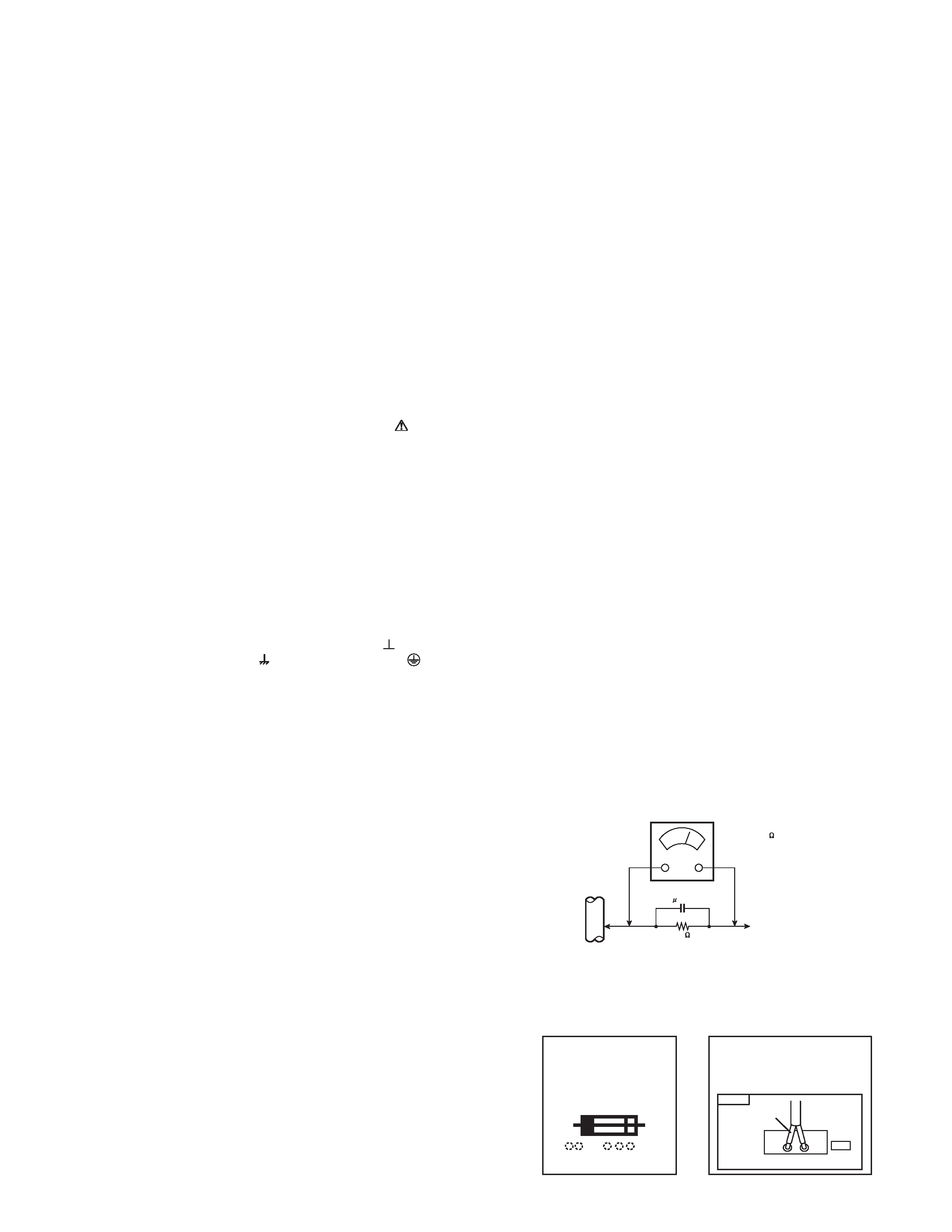
· Alternate Check Method
Plug the AC line cord directly into the AC outlet (do not use
a line isolation transformer during this check.). Use an AC
voltmeter having 1000 ohms per volt or more sensitivity in
the following manner. Connect a 1500ohm 10W resistor
paralleled by a 0.15µF AC-type capacitor between an
exposed metal part and a known good earth ground (water
pipe, etc.). Measure the AC voltage across the resistor with
the AC voltmeter. Move the resistor connection to each
exposed metal part, particularly any exposed metal part
having a return path to the chassis, and measure the AC
voltage across the resistor. Now, reverse the plug in the AC
outlet and repeat each measurement. Any voltage
measured must not exceed 0.75V AC (r.m.s.). This
corresponds to 0.5mA AC (r.m.s.).
However, in tropical area, this must not exceed 0.3V AC
(r.m.s.). This corresponds to 0.2mA AC (r.m.s.).
(11) High voltage hold down circuit check.
After repair of the high voltage hold down circuit, this circuit shall be
checked to operate correctly.
See item "How to check the high voltage hold down circuit".
AC VOLTMETER
(HAVING 1000 /V,
OR MORE SENSITIVITY)
PLACE THIS PROBE
ON EACH EXPOSED
METAL PART
1500
10W
0.15 F AC-TYPE
GOOD EARTH GROUND
PWB
White line side
WHT
PW
POWER CORD
REPLACEMENT WARNING.
Connecting the white line side of power
cord to "WHT" character side.
A
V
This mark shows a fast
operating fuse, the
letters indicated below
show the rating.
AV-N65P74
1-4 (No.52126)
1.2 INSTALLATION
1.2.1
REMOVING THE UPPER UNIT FROM THE LOWER UNIT
1.2.1.1
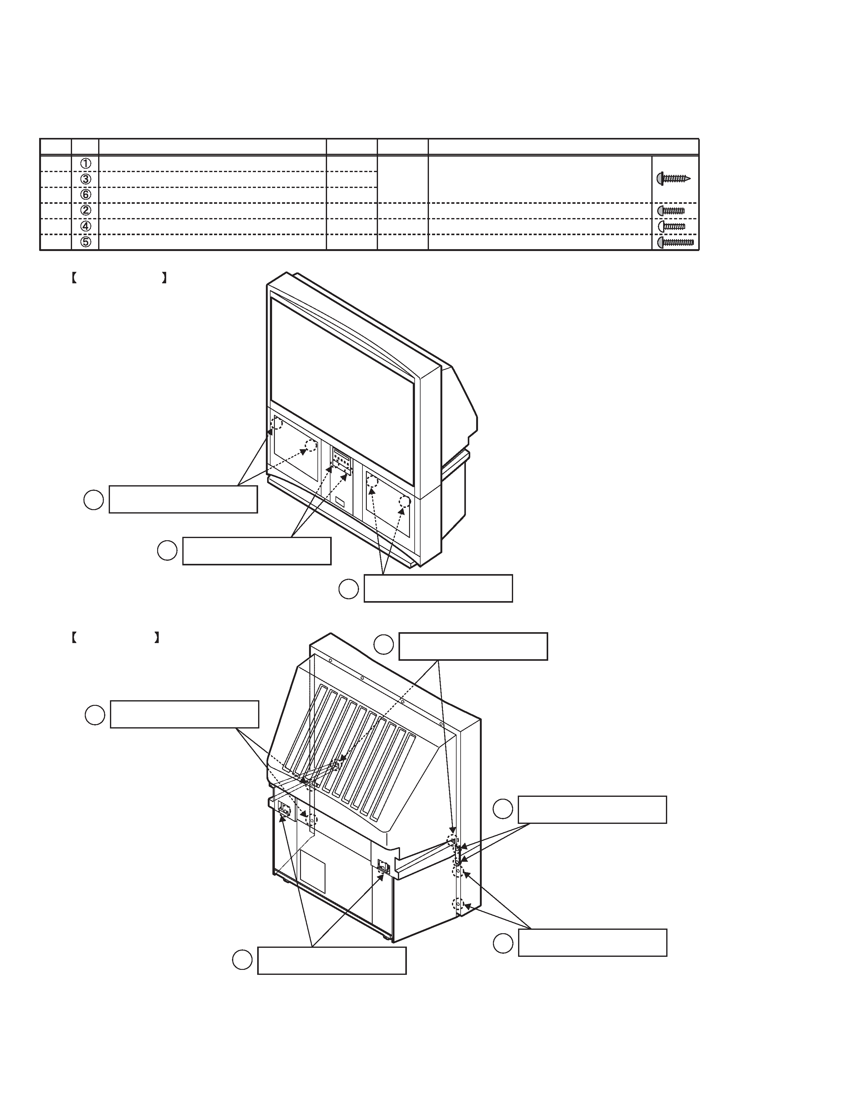
TYPES AND PLACES OF SCREWS
· Be careful not to confuse the following four types of screws.
Type
B
A
A
A
C
D
Ref.
Place for attaching screws
Quantity
Color
Shape
4
diameter of 4mm-length of 18mm, acute tip
diameter of 3mm-length of 12mm, flat tip
diameter of 4mm-length of 12mm, flat tip
diameter of 4mm-length of 20mm, flat tip
2
2
2
2
4
Black
Black
Gold
Black
Rear cover (for attaching the speaker panel)
FRONT SIDE
REAR SIDE
A : diameter of 4mm - length
of 18mm, black, acute tip
A : diameter of 4mm - length
of 18mm, black, acute tip
C : diameter of 4mm - length
of 12mm, gold, flat tip
D : diameter of 4mm - length
of 20mm, black, flat tip
B : diameter of 3mm - length
of 12mm, black, flat tip
Rear cover (for attaching the body bracket)
Inside the Front door (in the jack part)
Rear cover (for attaching the body)
Rear cover bracket
Front panel bracket
1
A : diameter of 4mm - length
of 18mm, black, acute tip
1
3
A : diameter of 4mm - length
of 18mm, black, acute tip
6
2
4
5
D : diameter of 4mm - length
of 20mm, black, flat tip
5

AV-N65P74
(No.52126)1-5
1.2.1.2
DISASSEMBLY PROCEDURE
· Make sure that the power cord is pulled out from the AC wall
socket.
(1) Remove the 2 screws [ A ] on the left rear side of the set,
and then remove the rear cover bracket. [Fig.1]
(2) Remove the 2 screws [ B ] inside of the front door. [Fig.2]
* The screws attach the speaker panel.
(3) Remove the 2 screws [ D ] on the left edge of the rear
cover, and remove the 2 screws [ D ] on the right edge of
the rear cover. [Fig.2]
* The screws attach the speaker panel.
(4) Pull the speaker grill in front direction, and remove the
speaker grill. [Fig.2]
(5) Remove the connector [CN00Z] for the auto-convergence
sensor on the left side of the set, and the clamp fixing the
wire. [Fig.2]
(6) Remove the 2 screws [ A ] on the left front panel bracket,
and remove the 2 screws [ A ] on the right front panel
bracket. [Fig.2]
(7) Remove 1 screw C on the left edge of the rear cover, and
1 screw C on the right edge of the rear cover. [Fig.3]
(8) Remove 1 screw [ A ] on the left side of the rear cover, and
remove 1 screw [ A ] on the right side of the rear cover.
[Fig.3]
(9) Move the rear cover approx. 3cm in rear direction. Then,
remove the upper unit from the lower unit by lifting the
upper unit slowly. [Fig.3]
·VOID seal [ a ] attached to the left front panel bracket in
order to confirm that a person except JVC installation
workers has disassembled the set. This seal is removed
when the upper unit is removed, and the letters of "VOID"
appears in the place where the seal. [Fig.2]
· Two or more people are required to move the upper unit.
· Reflecting mirror is attached to the upper unit. So, handle
it carefully so as to protect it from shocks.
· In placing the upper unit on the ground, be careful not to
insert the connector for the auto-convergence on the
right side of the upper unit between the upper unit and
the ground.
· In placing the upper unit on the ground, be careful not to
insert dust inside the upper unit.
· Be careful not to hurt yourself because metal brackets for
attaching the front panel are on the ceiling part of the
lower unit.
(10) Cover the lower unit with the Top Sheet in order not to
insert dust in the lower unit. Top Sheet is the one used for
package. [Fig.4]
Fig.1
Fig.2
Fig.3
Fig.4
A
REAR COVER
BRACKET
A
D
D
B
a
SPEAKER GRILL
CN00Z
C
A
UPPER
UNIT
LOWER
UNIT
TOP SHEET