No.51775
Jan. 2001
AV-61S902
COPYRIGHT © 2001 VICTOR COMPANY OF JAPAN, LTD.
AV-61S902 (US) / (CA)
CD-ROM : No.SML200102
CONTENTS
! SPECIFICATIONS
2
! SAFETY PRECAUTIONS
3
! SPECIFIC SERVICE INSTRUCTIONS
4
! SERVICE ADJUSTMENTS
13
BASIC CHASSIS
PD
SERVICE MANUAL
PROJECTION TELEVISION
PRELIMINARY
No.51775
AV-61S902
2
SPECIFICATIONS
Items
Contents
Dimensions (W×
×
×
×H×
×
×
×D)
145.1cm
× 150.8cm × 62.9cm (57-1/4" × 59-3/8" × 24-7/8")
Mass
117kg (258 lbs)
TV System and Color system
TV RF System
Color System
Sound System
1080i DTV (digital broadcast) ready
CCIR
M
NTSC
BTSC (Multi Channel Sound)
TV Receiving Channels and Frequency
VL Band
VH Band
UHF Band
02 ~ 06 : 54MHz ~ 88MHz
07 ~ 13 : 174MHz ~ 216MHz
14 ~ 69 : 470MHz ~ 806MHz
CATV Receiving Channels and Frequency
Low Band
High Band
Mid Band
Super Band
Hyper Band
Ultra Band
Sub Mid Band
TV/CATV Total Channel
54MHz ~ 806MHz
02 ~ 06, A-8 (by 02 ~ 06 & 01)
07 ~ 13 (by 07 ~ 13)
A ~ 1 (by 14 ~ 22)
J ~ W (by 23 ~ 36)
W+1 ~ W+28 (by 37 ~ 64)
W+29 ~ W+84 (by 65 ~ 125)
A8, A4 ~ A1 (by 01, 96 ~ 99)
181 Channels
Power Input
AC 120V, 60Hz
Power Consumption
430W
Projection System
D-ILA Hologram device 1.22" (1280
× 1028 × 3 pixels)
Light Source Lamp
200W
UHP (Ultra High-Pressure mercury) lamp
Screen
Transparent screen (united Fresnel lens & Double lenticular lens), aspect ratio 16:9
Screen Size
61-inch (155cm) : measured diagonally
[W: 135.1cm
× H: 76cm]
Speaker
Main (full range) : 10cm (3-15/16") Round type
×2
Bass (sub woofer) : 16cm (6-3/10") Round type
×2
Audio Power Output
Main (full range) : 5W+5W
Bass (sub woofer) : 10W+10W
Antenna terminal (75
VHF/UHF)
[INPUT A / INPUT B / SPLIT OUT]
SPLIT OUT : for CATV box connection
75
, F-type connector ×3
Input (INPUT 1 / 2 / 3 / 4 / 5)
Video
Audio (L/R)
S-Video
Component-Video
[INPUT 2 / 3]
INPUT-5 : Audio (L/R) only
1V(p-p), 75
RCA pin jack
×4
500mV(rms) (-4dBs), high impedance
RCA pin jack
×10
mini-DIN 4-pin connector
×4
Y : 1V(p-p) positive, 75
(negative sync. provided)
C : 0.286V(p-p), 75
(burst signal)
RCA pin jack
×6
Y : 1V(p-p) positive, 75
(3-values sync. provided)
PB / PR : 0.7V(p-p) [±0.35V], 75
RCA pin jack
Digital Input (INPUT-5)
DVI (Digital Visual Interface) 25-pin connector
×1
Output (LINE OUT)
Video
Audio (L/R)
S-Video
1V(p-p), 75
RCA pin jack ×1
500mV(rms) (-4dBs), high impedance
RCA pin jack
×2
mini-DIN 4-pin jack
×1
Y : 1V(p-p) positive, 75
(negative sync. provided)
C : 0.286V(p-p), 75
(burst signal)
Audio Output (FRONT / SURROUND REAR)
[FRONT = Variable / Fix : Selectable]
[SURROUND REAR = Fix only]
RCA pin jack
×4
Variable : More then 0 ~ 1550mV(rms) (+6dBs)
/
Fix : 500mV(rms) (-4dBs)
Low impedance (400Hz when modulated 100%)
AV COMPULINK EX Input
3.5mm mini jack (Monaural type)
Remote Control Unit
RM-C308
(Dry cell battery : AA/R6/UM-3
×2)
Option
Lamp unit [PK-CL200U]
Design & specification are subject to change without notice.
No.51775
AV-61S902
3
SAFETY PRECAUTIONS
1.
The design of this product contains special hardware, many
circuits and components specially for safety purposes. For
continued protection, no changes should be made to the original
design unless authorized in writing by the manufacturer.
Replacement parts must be identical to those used in the original
circuits. Service should be performed by qualified personnel only.
2.
Alterations of the design or circuitry of the products should not be
made. Any design
alterations or additions
will void
the
manufacturer's warranty and will further relieve the manufacturer
of responsibility for personal injury or property damage resulting
therefrom.
3.
Many electrical and mechanical parts in the products have
special safety-related characteristics. These characteristics are
often not evident from visual inspection nor can the protection
afforded by them necessarily be obtained by using replacement
components rated for higher voltage, wattage, etc. Replacement
parts which have these special safety characteristics are
identified in the parts list of Service manual. Electrical
components having such features are identified by shading
on the schematics and by (!
!
!
!) on the parts list in Service
manual. The use of a substitute replacement which does not
have the same safety characteristics as the recommended
replacement part shown in the parts list of Service manual may
cause shock, fire, or other hazards.
4.
Use isolation transformer when hot chassis.
The chassis and any sub-chassis contained in some products are
connected to one side of the AC power line. An isolation
transformer of adequate capacity should be inserted between the
product and the AC power supply point while performing any
service on some products when the HOT chassis is exposed.
5.
Don't short between the LIVE side ground and ISOLATED
(NEUTRAL) side ground or EARTH side ground when
repairing.
Some model's power circuit is partly different in the GND. The
difference of the GND is shown by the LIVE : (") side GND, the
ISOLATED(NEUTRAL) : (#) side GND and EARTH : ($) side
GND.
Don't
short
between
the
LIVE
side
GND
and
ISOLATED(NEUTRAL) side GND or EARTH side GND and
never measure with a measuring apparatus (oscilloscope etc.) the
LIVE side GND and ISOLATED(NEUTRAL) side GND or
EARTH side GND at the same time.
If above note will not be kept, a fuse or any parts will be broken.
6.
If any repair has been made to the chassis, it is recommended
that the B1 setting should be checked or adjusted (See
ADJUSTMENT OF B1 POWER SUPPLY).
7.
The high voltage applied to the picture tube must conform with
that specified in Service manual. Excessive high voltage can
cause an increase in X-Ray emission, arcing and possible
component damage, therefore operation under excessive high
voltage conditions should be kept to a minimum, or should be
prevented. If severe arcing occurs, remove the AC power
immediately and determine the cause by visual inspection
(incorrect installation, cracked or melted high voltage harness,
poor soldering, etc.). To maintain the proper minimum level of soft
X-Ray emission, components in the high voltage circuitry
including the picture tube must be the exact replacements or
alternatives approved by the manufacturer of the complete
product.
8.
Do not check high voltage by drawing an arc. Use a high voltage
meter or a high voltage probe with a VTVM. Discharge the picture
tube before attempting meter connection, by connecting a clip
lead to the ground frame and connecting the other end of the lead
through a 10k 2W resistor to the anode button.
9.
When service is required, observe the original lead dress. Extra
precaution should be given to assure correct lead dress in the
high voltage circuit area. Where a short circuit has occurred,
those components that indicate evidence of overheating should be
replaced.
Always
use
the
manufacturer's
replacement
components.
10. Isolation Check
(Safety for Electrical Shock Hazard)
After re-assembling the product, always perform an isolation
check on the exposed metal parts of the cabinet (antenna
terminals, video/audio input and output terminals, Control knobs,
metal cabinet, screwheads, earphone jack, control shafts, etc.) to
be sure the product is safe to operate without danger of electrical
shock.
(1) Dielectric Strength Test
The isolation between the AC primary circuit and all metal parts
exposed to the user, particularly any exposed metal part having a
return path to the chassis should withstand a voltage of 1100V
AC (r.m.s.) for a period of one second.
(. . . . Withstand a voltage of 1100V AC (r.m.s.) to an appliance
rated up to 120V, and 3000V AC (r.m.s.) to an appliance rated
200V or more, for a period of one second.)
This method of test requires a test equipment not generally found
in the service trade.
(2) Leakage Current Check
Plug the AC line cord directly into the AC outlet (do not use a line
isolation transformer during this check.). Using a "Leakage
Current Tester", measure the leakage current from each exposed
metal part of the cabinet, particularly any exposed metal part
having a return path to the chassis, to a known good earth ground
(water pipe, etc.). Any leakage current must not exceed 0.5mA
AC (r.m.s.).
However, in tropical area, this must not exceed 0.2mA AC
(r.m.s.).
!
!
!
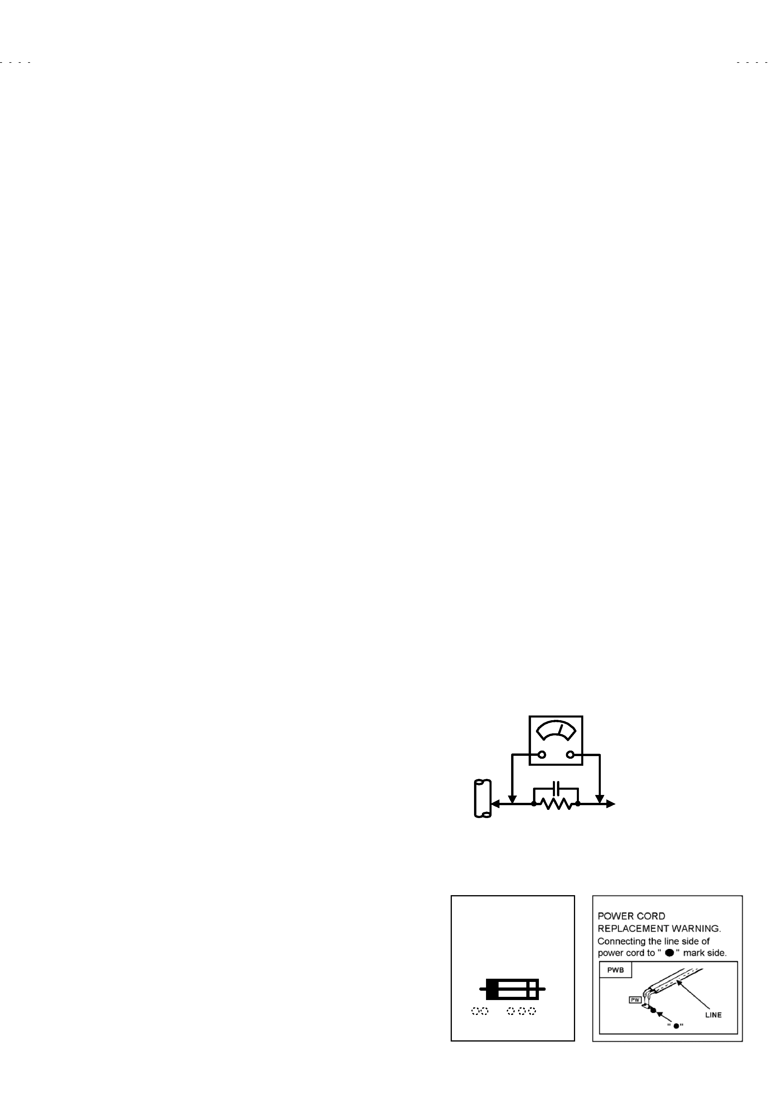
! Alternate Check Method
Plug the AC line cord directly into the AC outlet (do not use a line
isolation transformer during this check.). Use an AC voltmeter
having 1000 ohms per volt or more sensitivity in the following
manner. Connect a 1500 10W resistor paralleled by a 0.15F
AC-type capacitor between an exposed metal part and a known
good earth ground (water pipe, etc.). Measure the AC voltage
across the resistor with the AC voltmeter. Move the resistor
connection to each exposed metal part, particularly any exposed
metal part having a return path to the chassis, and measure the
AC voltage across the resistor. Now, reverse the plug in the AC
outlet and repeat each measurement. Any voltage measured must
not exceed 0.75V AC (r.m.s.).
This corresponds to 0.5mA AC
(r.m.s.).
However, in tropical area, this must not exceed 0.3V AC (r.m.s.).
This corresponds to 0.2mA AC (r.m.s.).
0.15F AC-TYPE
1500 10W
GOOD
EARTH
GROUND
PLACE THIS PROBE
ON EACH EXPOSED
METAL PART
AC VOLTMETER
(HAVING 1000 /V,
OR MORE SENSITIVITY)
11. High voltage hold down circuit check.
After repair of the high voltage hold down circuit, this circuit shall
be checked to operate correctly.
See item "How to check the high voltage hold down circuit".
A
V
This mark shows a fast
operating fuse, the
letters indicated below
show the rating.

No. 51775
AV-61S902
4
SPECIFIC SERVICE INSTRUCTIONS
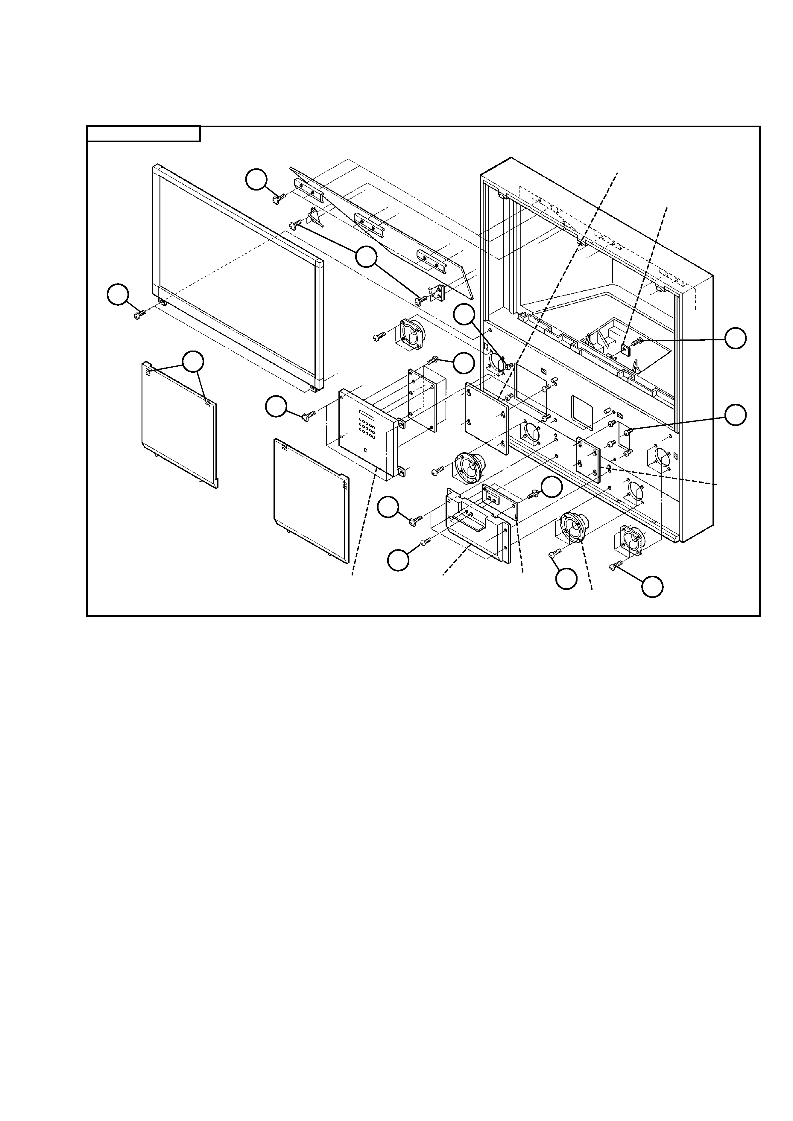
DISASSEMBLY PROCEDURE
1. FRONT SIDE -1
SPEAKER GRILLE
1) Pull outward and remove 2 adhesive tapes [A].
Take out the
SPEAKER GRILLE.
! Both left and right have the same construction.
UPPER FRONT PANEL
Take out the left and right SPEAKER GRILLES.
1) Remove 4 screws [B] and take out the UPPER FRONT PANEL.
FRONT CONTROL PWB ASS'Y
Take out the UPPER FRONT PANEL.
1) Disengage interior connectors (X3 / X4).
2) Remove 5 screws [C] and take out the FRONT CONTROL PWB
ASS'Y.
LOWER FRONT PANEL
Take out the UPPER FRONT PANEL.
1) Remove 4 screws [D] and take out the LOWER FRONT PANEL.
FRONT JACK PWB ASS'Y
Take out the LOWER FRONT PANEL.
1) Disengage interior connectors (AM / F).
2) Remove 2 screws [E] and 2 screws [F].
Take out the FRONT
JACK PWB ASS'Y.
FILTER COVER
" Take out the FILTER COVER when take out the LAMP FILTER
COVER and replacing the LAMP UNIT.
Take out the left SPEAKER GRILLE.
1) Loosen 4 screws [G].
2) Pull upward and take out the FILTER COVER.
ADJUSTMENT COVER
" Take out the ADJUSTMENT COVER when using a personal
computer for adjustment.
Take out the right SPEAKER GRILLE.
1) Loosen 4 screws [H].
2) Pull upward and take out the ADJUSTMENT COVER.
! When adjustment used the PC, connect the PC to the adjustment
terminal (RS-232C control : D-sub 9-pin connector) .
MAIN SPEAKER
Take out the left and right SPEAKER GRILLES.
1) Remove 4 screws [I].
2) Disengage the connecting wires and take out the MAIN
SPEAKER.
! Both left and right have the same construction.
BASS SPEAKER
Take out the left and right SPEAKER GRILLES.
1) Support the speaker front and take out 4 screws [J].
2) Disengage the connecting wires and take out the BASS
SPEAKER.
! Both left and right have the same construction.
! The BASS SPEAKERS are important. Use care not to drop or
damage them.
SCREEN ASS'Y
Take out the left and right SPEAKER GRILLES.
1) Remove 2 screws [K].
2) Pull upward and take out the SCREEN ASS'Y.
! Use care not to scratch the front of the screen
! When transporting, avoid grasping the top of the SCREEN ASS'Y.
Grasp the left and right sides or bottom.
! When reassembling, observe the left and right pins of the cabinet
are engaged with the rear left and right hooks of the frame at
SCREEN ASS'Y.
Also check insertion into the 3 slits at the
lower front of the cabinet.
MIRROR
! Wear protective gloves to avoid contaminating the MIRROR.
Take out the SCREEN ASS'Y.
1) Remove 4 left and right screws [L] together with the holder.
2) Support upper part of the MIRROR, remove 6 screws [M]
together with the holder and take out the MIRROR.
! The MIRROR is heavy and easily broken.
Use care not to
impart physical shock.
REMOTE CONTROL SENSOR PWB ASS'Y
Take out the SCREEN ASS'Y.
1) Remove 1 screw [N] and take out the REMOTE CONTROL
SENSOR PWB ASS'Y.
! Since the projector lens is nearby, use care not to soil or scratch
the lens projection side.
No. 51775
AV-61S902
5
SCREEN ASS'Y
M
K
A
B
D
E
I
F
J
G
C
N
H
MIRROR
SPEAKER GRILLE
UPPER
FRONT PANEL
BASS SPEAKER
MAIN SPEAKER
LOWER
FRONT PANEL
FRONT JACK
PWB ASS'Y
REMOTE CONTROL
SENSOR PWB ASS'Y
FRONT
CONTROL
PWB ASS'Y
1.
FRONT SIDE -1
L
ADJUSTMENT
COVER
FILTER
COVER