SERVICE MANUAL
COPYRIGHT © 2003 VICTOR COMPANY OF JAPAN, LTD.
No.52104
2003/04
AV-32430
AV-32432
COLOR TELEVISION
52104
2003
04
AV-32430/M, AV-32432/M,
AV-32430/R, AV-32432/R,
AV-32430/Y, AV-32432/Y
TABLE OF CONTENTS
1
PRECAUTIONS . . . . . . . . . . . . . . . . . . . . . . . . . . . . . . . . . . . . . . . . . . . . . . . . . . . . . . . . . . . . . . . . . . . . . . . 1-3
2
SPECIFIC SERVICE INSTRUCTIONS . . . . . . . . . . . . . . . . . . . . . . . . . . . . . . . . . . . . . . . . . . . . . . . . . . . . . . 1-4
3
ADJUSTMENT . . . . . . . . . . . . . . . . . . . . . . . . . . . . . . . . . . . . . . . . . . . . . . . . . . . . . . . . . . . . . . . . . . . . . . . 1-12
BASIC CHASSIS
GE2
AV-32430
AV-32432
1-2 (No.52104)
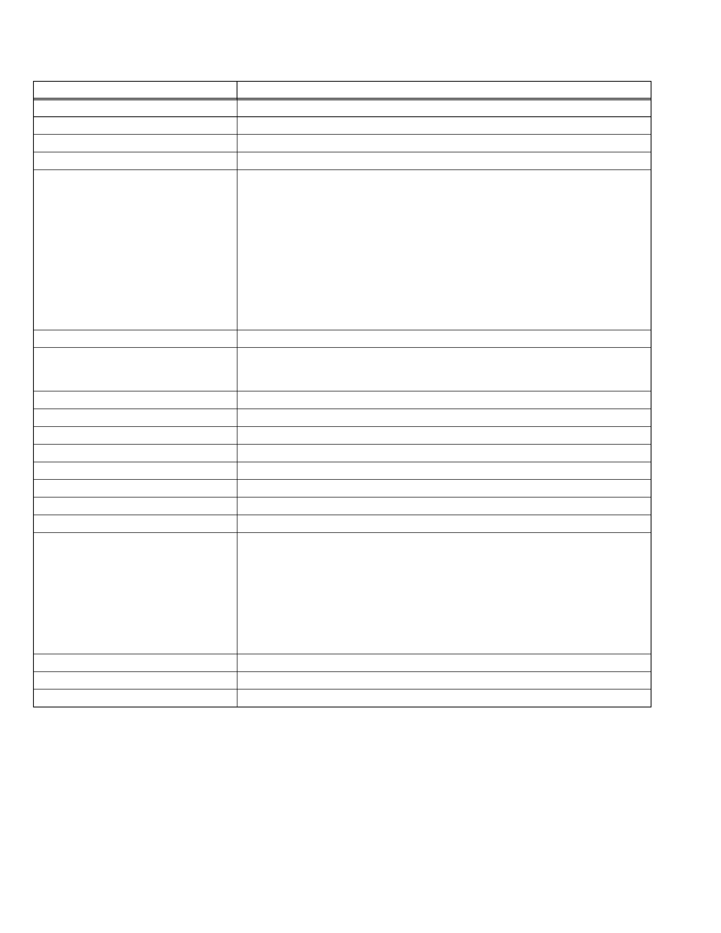
SPECIFICATION
Design & specifications are subject to change without notice.
Items
Contents
Dimensions (W x H x D)
76.8cm x 66.7cm x 54.7cm (30-1/4" x 26-1/4" x 21-1/2")
Mass
51.0kg (112.2 Ibs)
TV RF System
CCIR (M)
Color Sound System
NTSC, BTSC System (Multi Channel Sound)
TV Receiving Channels and Frequency
VHF LOW
VHF HIGH
UHF
CATV
02ch~06ch : 54MHz~88MHz
07ch~13ch : 174MHz~216MHz
14ch~69ch : 470MHz~806MHz
54MHz~804MHz
Low Band : 02~06, A-8 by 02~06&01
High Band : 07~13 by 07~13
Mid Band : A~1 by 14~22
Super Band : J~W by 23~36
Hyper Band : W+1~W+28 by 37~64
Ultra Band : W+29~W+84 by 65~125
Sub Mid Band : A8, A4~A1 by 01, 96~99
TV/CATV Total Channel
180 Channels
Intermediate Frequency
Video IF Carrier
Sound IF Carrier
45.75MHz
41.25MHz (4.5MHz)
Color Sub Carrier
3.58MHz
Power Input
AC 120V, 60Hz
Power Consumption
128W
Picture Tube
32" (80cm) Measured diagonally
H:65.6cm x V:49.6cm
High Voltage
31kV±1.3kV (at zero beam current)
Speaker
8 x 12cm (3-1/4" x 4-3/4") Oval type x 2
Audio Power Output
3W + 3W
Antenna Terminal (VHF/UHF)
F-type connector, 75ohm
Video / Audio Input (1 / 2 / 3)
Video (1 / 3)
Audio (1 / 2 / 3)
S-Video (1)
Component video (2)
1V(p-p), 75ohm (RCA pin jack x 2)
500mV(rms) (-4dBs), high impedance (RCA pin jack x 8)
Mini DIN 4pin x 1
Y : 1V(p-p) positive (negative sync provided, when terminated with 75ohm)
C : 0.286V(p-p) (burst signal when terminated with 75ohm)
RCA pin jack x 3
Y : 1V(p-p) positive (negative sync provided, when terminated with 75ohm)
Pb/Pr : 0.7V(p-p) 75ohm
Audio Output (Fix)
500mV(rms), low impedance, (1kHz when modulated 100%) (RCA pin jack x 2)
AV Compulink lll
3.5mm mini jack x 1
Remote Control Unit
RM-C203 (Lithium cell battery x 1)
AV-32430
AV-32432
(No.52104)1-3
SECTION 1
PRECAUTIONS
1.1 SAFETY PRECAUTIONS
(1) The design of this product contains special hardware, many circuits
and components specially for safety purposes. For continued
protection, no changes should be made to the original design unless
authorized in writing by the manufacturer. Replacement parts must
be identical to those used in the original circuits. Service should be
performed by qualified personnel only.
(2) Alterations of the design or circuitry of the products should not be
made. Any design alterations or additions will void the manufacturer's
warranty and will further relieve the manufacturer of responsibility for
personal injury or property damage resulting therefrom.
(3) Many electrical and mechanical parts in the products have special
safety-related characteristics. These characteristics are often not
evident from visual inspection nor can the protection afforded by them
necessarily be obtained by using replacement components rated for
higher voltage, wattage, etc. Replacement parts that have these
special safety characteristics are identified in the parts list of Service
manual. Electrical components having such features are
identified by shading on the schematics and by (
) on the parts
list in Service manual. The use of a substitute replacement which
does not have the same safety characteristics as the recommended
replacement part shown in the parts list of Service manual may cause
shock, fire, or other hazards.
(4) Use isolation transformer when hot chassis.
The chassis and any sub-chassis contained in some products are
connected to one side of the AC power line. An isolation transformer
of adequate capacity should be inserted between the product and the
AC power supply point while performing any service on some
products when the HOT chassis is exposed.
(5) Don't short between the LIVE side ground and ISOLATED
(NEUTRAL) side ground or EARTH side ground when repairing.
Some model's power circuit is partly different in the GND. The
difference of the GND is shown by the LIVE : (
) side GND, the
ISOLATED(NEUTRAL) : ( ) side GND and EARTH : (
) side GND.
Don't short between the LIVE side GND and ISOLATED(NEUTRAL)
side GND or EARTH side GND and never measure with a measuring
apparatus
(oscilloscope
etc.)
the
LIVE
side
GND
and
ISOLATED(NEUTRAL) side GND or EARTH side GND at the same
time.
If above note will not be kept, a fuse or any parts will be broken.
(6) The high voltage applied to the picture tube must conform with that
specified in Service manual. Excessive high voltage can cause an
increase in X-Ray emission, arcing and possible component damage,
therefore operation under excessive high voltage conditions should
be kept to a minimum, or should be prevented. If severe arcing
occurs, remove the AC power immediately and determine the cause
by visual inspection (incorrect installation, cracked or melted high
voltage harness, poor soldering, etc.). To maintain the proper
minimum level of soft X-Ray emission, components in the high
voltage circuitry including the picture tube must be the exact
replacements or alternatives approved by the manufacturer of the
complete product.
(7) If any repair has been made to the chassis, it is recommended that
the B1 setting should be checked or adjusted (See ADJUSTMENT
OF B1 POWER SUPPLY).
(8) Do not check high voltage by drawing an arc. Use a high voltage
meter or a high voltage probe with a VTVM. Discharge the picture
tube before attempting meter connection, by connecting a clip lead to
the ground frame and connecting the other end of the lead through a
10k
2W resistor to the anode button.
(9) When service is required, observe the original lead dress. Extra
precaution should be given to assure correct lead dress in the high
voltage circuit area. Where a short circuit has occurred, those
components that indicate evidence of overheating should be
replaced. Always use the manufacturer's replacement components.
(10) Isolation Check
(Safety for Electrical Shock Hazard)After re-assembling the
product, always perform an isolation check on the exposed metal
parts of the cabinet (antenna terminals, video/audio input and output
terminals, Control knobs, metal cabinet, screwheads, earphone jack,
control shafts, etc.) to be sure the product is safe to operate without
danger of electrical shock.
a) Dielectric Strength Test
The isolation between the AC primary circuit and all metal
parts exposed to the user, particularly any exposed metal part
having a return path to the chassis should withstand a voltage
of 1100V AC (r.m.s.) for a period of one second.
(. . . . Withstand a voltage of 1100V AC (r.m.s.) to an appliance
rated up to 120V, and 3000V AC (r.m.s.) to an appliance rated
200V or more, for a period of one second.)
This method of test requires test equipment not generally
found in the service trade.
b) Leakage Current Check
Plug the AC line cord directly into the AC outlet (do not use a
line isolation transformer during this check.). Using a "Leakage
Current Tester", measure the leakage current from each
exposed metal part of the cabinet, particularly any exposed
metal part having a return path to the chassis, to a known good
earth ground (water pipe, etc.). Any leakage current must not
exceed 0.5mA AC (r.m.s.). However, in tropical area, this must
not exceed 0.2mA AC (r.m.s).
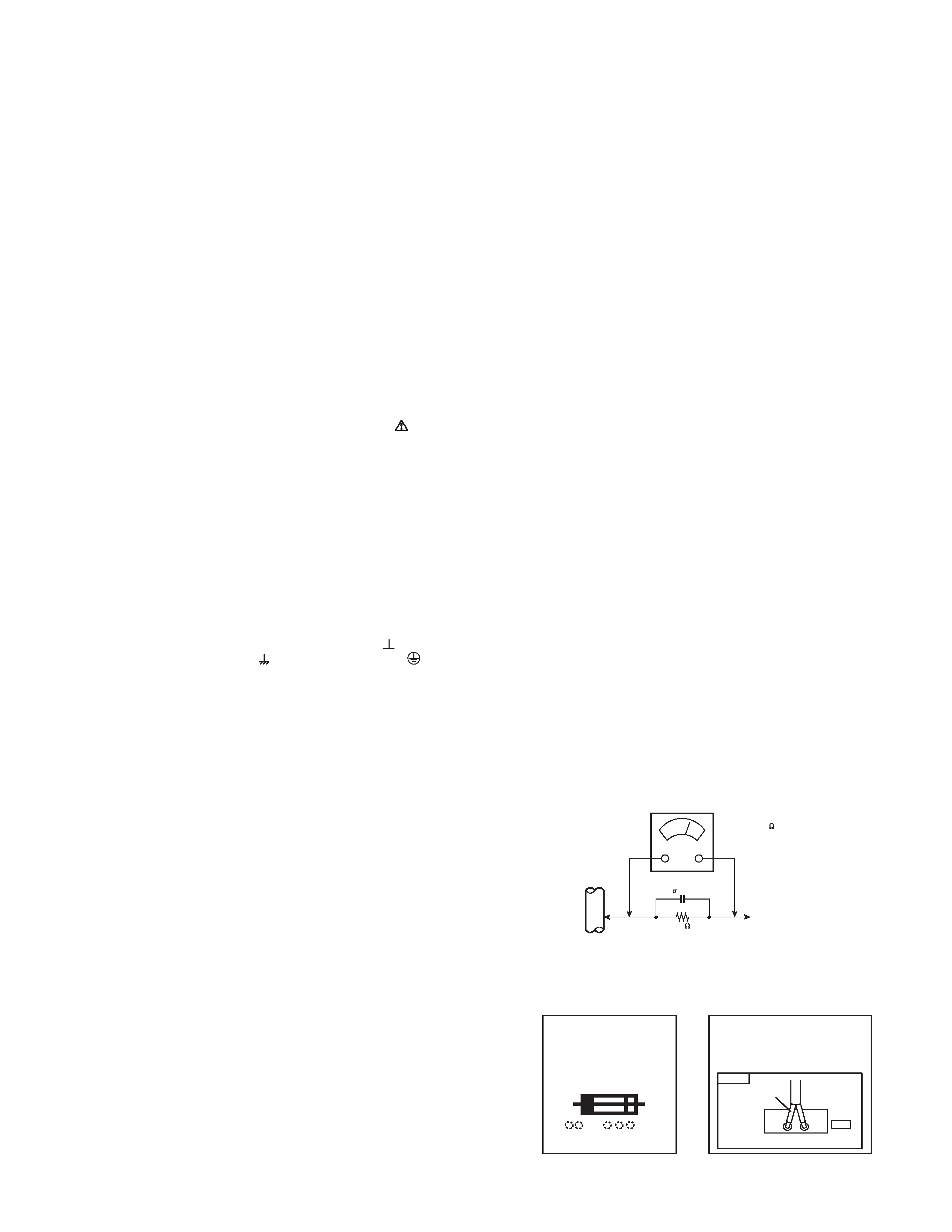
· Alternate Check Method
Plug the AC line cord directly into the AC outlet (do not use
a line isolation transformer during this check.). Use an AC
voltmeter having 1000 ohms per volt or more sensitivity in
the following manner. Connect a 1500ohm 10W resistor
paralleled by a 0.15µF AC-type capacitor between an
exposed metal part and a known good earth ground (water
pipe, etc.). Measure the AC voltage across the resistor with
the AC voltmeter. Move the resistor connection to each
exposed metal part, particularly any exposed metal part
having a return path to the chassis, and measure the AC
voltage across the resistor. Now, reverse the plug in the AC
outlet and repeat each measurement. Any voltage
measured must not exceed 0.75V AC (r.m.s.). This
corresponds to 0.5mA AC (r.m.s.).
However, in tropical area, this must not exceed 0.3V AC
(r.m.s.). This corresponds to 0.2mA AC (r.m.s.).
(11) High voltage hold down circuit check.
After repair of the high voltage hold down circuit, this circuit shall be
checked to operate correctly.
See item "How to check the high voltage hold down circuit".
AC VOLTMETER
(HAVING 1000 /V,
OR MORE SENSITIVITY)
PLACE THIS PROBE
ON EACH EXPOSED
METAL PART
1500
10W
0.15 F AC-TYPE
GOOD EARTH GROUND
PWB
White line side
WHT
PW
POWER CORD
REPLACEMENT WARNING.
Connecting the white line side of power
cord to "WHT" character side.
A
V
This mark shows a fast
operating fuse, the
letters indicated below
show the rating.
AV-32430
AV-32432
1-4 (No.52104)
SECTION 2
SPECIFIC SERVICE INSTRUCTIONS
2.1 FEATURES
2.2 MAIN DIFFERENCE LIST
· The difference between MA models, RA model, and YA models is in the PICTURE TUBE. As the result of the difference in PICTURE
TUBE, the MAIN PWB also differ.
· The difference between AV-32430 series models and AV-32432 series models are in the FRONT CABINET color.
TELETEXT (CLOSED CAPTION)
Title TELETEXT broadcast of C1~C4 and T1~T4 formula is receivable.
DIGITAL COMB FILTER
By the three-line digital comb filter, the refreshed image can be seen.
VIDEO STATUS
Expression of a favorite screen can be chosen by the VIDEO STATUS function
(STANDARD / DYNAMIC / SPORTS / GAME).
V-CHIP
Since the V chip is built in, it can choose, view and listen to a healthy program.
COMPONENT VIDEO INPUT TERMINAL Since the component signal input terminal is equipped, it reappears direct without
deteriorating the signal from DVD.
MTS STEREO SYSTEM
The voice multiplex function of the MTS system is built in. (MTS = Multi channel TV
Sound system)
EZ SURF
By the EZ SURF function, channel ID and a program name are displayed in the screen
automatically.
RETURN PLUS
you program a specific channel to return to while scanning through the channels using
the CH+ and CH- buttons.
AV COMPULINK lll
By the AV COMPULINK lll function, operation interlocked with the DVD deck can be
performed from remote control.
ON / OFF & SLEEP TIMER
The on/off timer lets you program your television to turn itself on or off. You can use it as
an alarm to wake up, to help you remember important programs, or as a decoy when
you're not home.
HYPER SCAN
A quick favorite program can be looked for by the HYPER SCAN function.
FRONT PANEL LOCK
This allows you to lock the keys on the front of the TV, so that a child may not accidentally
change your viewing preferences.
NOISE MUTING
This feature inserts a blank blue screen over channels which are not broadcasting or are
too weak to be received clearly.
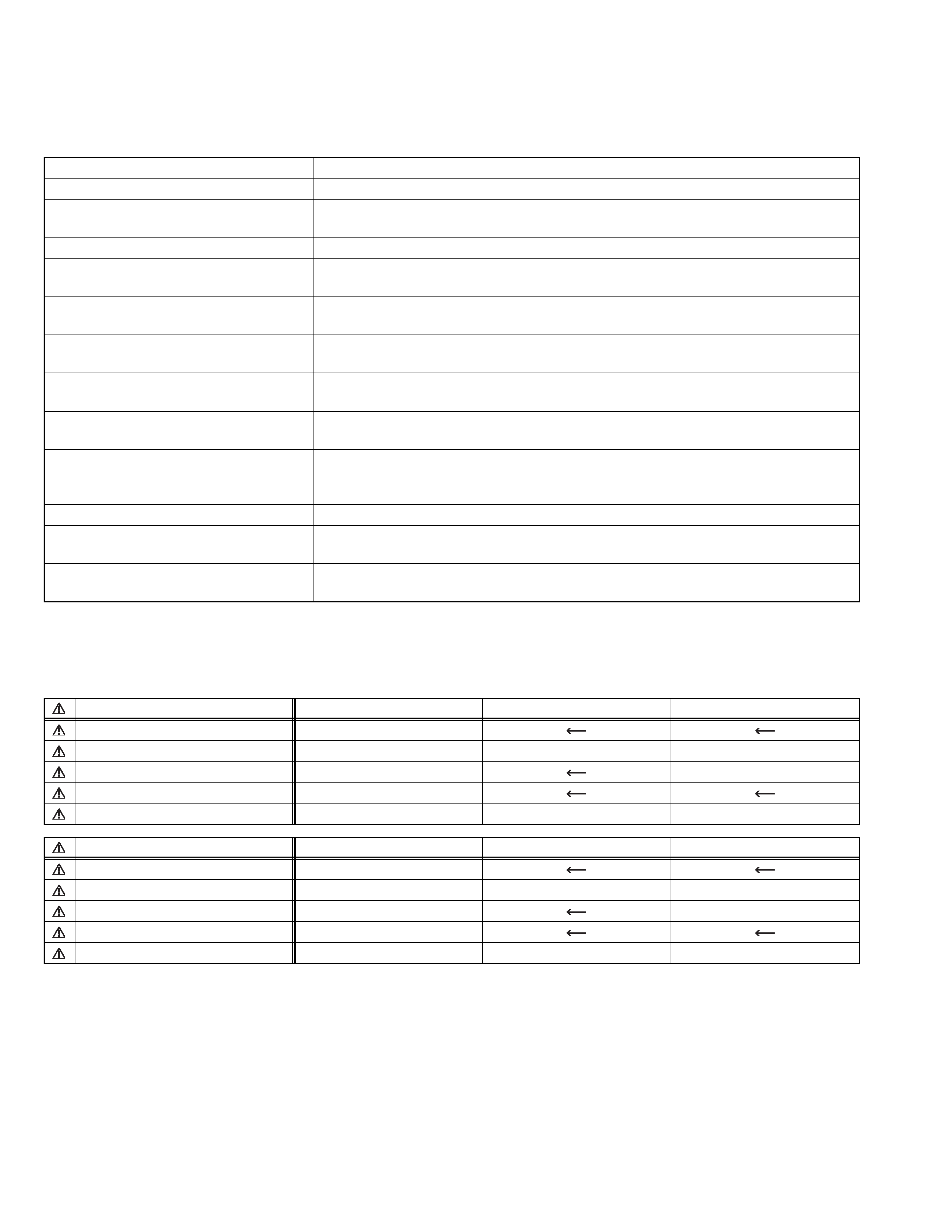
PART NAME
AV-32430/MA
AV-32430/RA
AV-32430/YA
FRONT CABINET (BLACK)
CM12914-010-MA
MAIN P.W.B. ASSY
SGE-1064A-M2
SGE-1066A-M2
SGE-1065A-M2
CRT SOCKET P.W.B. ASSY
SGE-3061A-M2
SGE-3062A-M2
AV SELECT P.W.B. ASSY
SGE-5062A-M2
PICTURE TUBE (ITC)
M80JUA061X06
A80AEJ15X01
A80AKB50X04
PART NAME
AV-32432/MA
AV-32432/RA
AV-32432/YA
FRONT CABINET (SILVER)
CM12914-012-MA
MAIN P.W.B. ASSY
SGE-1061A-M2
SGE-1063A-M2
SGE-1062A-M2
CRT SOCKET P.W.B. ASSY
SGE-3061A-M2
SGE-3062A-M2
AV SELECT P.W.B. ASSY
SGE-5061A-M2
PICTURE TUBE (ITC)
M80JUA061X06
A80AEJ15X01
A80AKB50X04
AV-32430
AV-32432
(No.52104)1-5
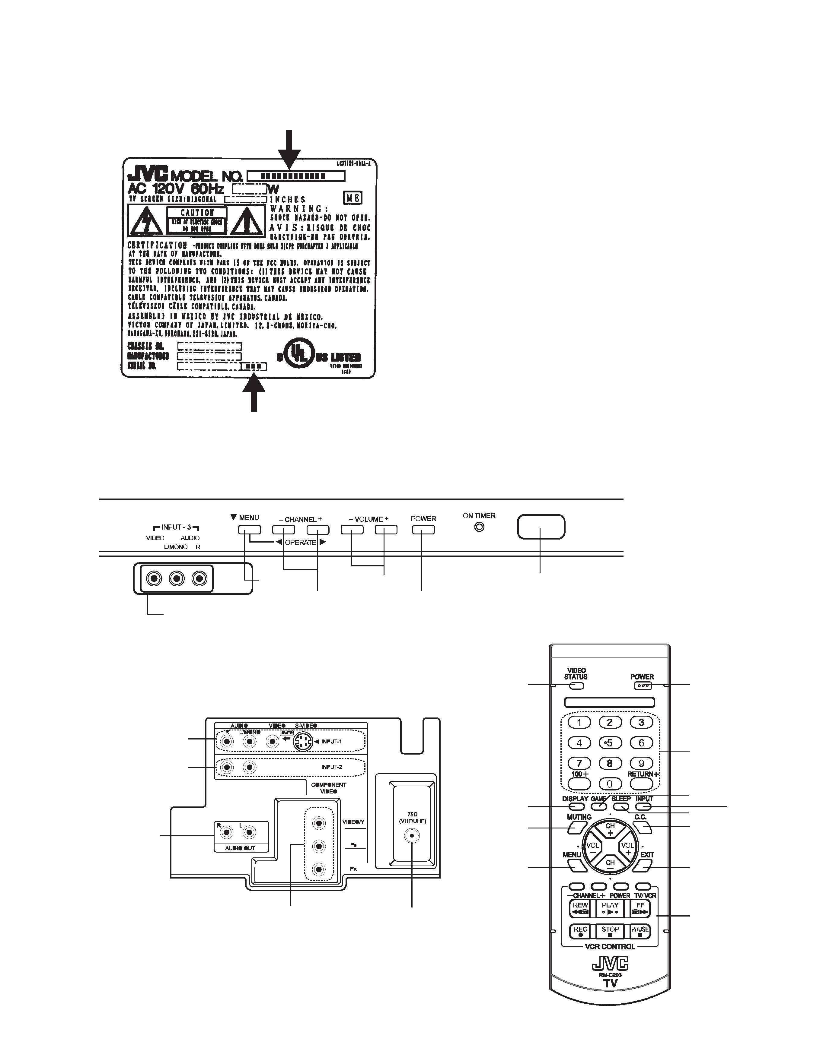
2.3 HOW TO IDENTIFY MODELS
How to recognize from the appearance of the model concerned is written below.
Please distinguish from several contents printed on the rating label.
2.4 FUNCTIONS
Indicated model name
Indicated /M, /R or /Y model
MENU
CHANNEL -/+
INPUT-3 (V, L, R)
INPUT-1
(S, V, L, R)
INPUT-2
(L, R)
INPUT-2
(Y, Pb, Pr)
ANTENNA
TERMINAL
VIDEO
STATUS
VCR
CONTROL
KEYS
DISPLAY
POWER
BUTTON
NUMBER
KEYS
MUTING
MENU
GAME
SLEEP
C.C
EXIT
INPUT
AUDIO OUT
(L, R)
VOLUME -/+
POWER SW
REMOCON
WINDOW
FRONT CONTROL PANEL
REAR TERMINAL
REMOTE CONTROL UNIT