No.51946
May 2002
AV-27D503
1
COPYRIGHT © 2002 VICTOR COMPANY OF JAPAN, LTD.
AV-27D503
/S
AV-27D503
/R
CONTENTS
!
SPECIFICATIONS
2
! SAFETY PRECAUTIONS
3
!
FEATURES
4
!
HOW TO IDENTIFY MODELS
4
! FUNCTIONS
4
!
SPECIFIC SERVICE INSTRUCTIONS
6
! SERVICE ADJUSTMENTS
10
! PARTS LIST
31
STANDARD CIRCUIT DIAGRAM
2-1
SERVICE MANUAL
COLOR TELEVISION
BASIC CHASSIS
GE
No.51946
AV-27D503
2
SPECIFICATIONS
Items
Contents
Dimensions (W×
×
×
×
H×
×
×
×
D)
29-5/8"×23-1/4"×19-1/2"
(752mm×591mm×494mm)
Mass
71.3Ibs (32.4kg)
TV System and Color system
TV RF System
Color System
Sound System
CCIR(M)
NTSC-M
BTSC (Multi Channel Sound)
TV Receiving Channels and Frequency
VL Band
VH Band
UHF Band
(0206) 54MHz88MHz
(0713) 174MHz216MHz
(1469) 470MHz806MHz
CATV Receiving Channels and Frequency
Low Band
High Band
Mid Band
Super Band
Hyper Band
Ultra Band
Sub Mid Band
TV/CATV Total Channel
(0206, A-8) by (0206&01)
(0713) by (0713)
(A1) by (1422)
(JW) by (2336)
(W+1W+28) by (3764)
(W+29W+84) by (65125)
(A8, A4A1) by (01, 9699)
180 Channels
Intermediate Frequency
Video IF Carrier
Sound IF Carrier
45.75 MHz
41.25 MHz (4.5MHz)
Color Sub Carrier
3.58 MHz
Power Input
120V AC, 60Hz
Power Consumption
123W
Picture Tube
27" (68cm) measured diagonally, Full Square
High Voltage
29kV±1.3kV (at zero beam current)
Speaker
2"×4-3/4" (5×12cm) Oval type×2
Audio Power Output
5W+5W
Input terminals
INPUT1
Video
S-Video
Audio (L,R)
INPUT2
Video
Component (Y,Pb,Pr)
Audio (L,R)
INPUT3
Video
(Front)
Audio (L,R)
1Vp-p 75 (RCA pin jack)
Y :1Vp-p positive (negative sync provided, when terminated with 75)
C: 0.286Vp-p (burst s ignal, when terminated with 75)
500mVrms (-4dBs), High Impedance (RCA pin jack)
1Vp-p 75 (RCA pin jack)
Y: 1Vp-p positive (negative sync provided, when terminated with 75)
PB/PR: 0.7Vp-p 75
500mVrms (-4dBs), High Impedance (RCA pin jack)
1Vp-p 75 (RCA pin jack)
500mVrms (-4dBs), High Impedance (RCA pin jack)
Audio Output
500mVrms(-4dBs)
Low Impedance (400Hz when modulated 100%) (RCA pin jack)
AV Compu link EX Input
3.5mm mini jack
Antenna terminal
75 (VHF/UHF) Terminal, F-Type Connector
Remote Control Unit
RM-C251 (AA/R6/UM-3 battery×2)
Design & specifications are subject to change without notice.
(54MHz804MHz)
No. 51946
AV-27D503
3
SAFETY PRECAUTIONS
1. The design of this product c ontains spec ial hardware, many
circuits and components s pecially for safety purposes. For
continued protection, no changes should be made to the
original des ign unless authorized in writing by the manufacturer.
Replacement parts must be identic al to thos e used in the
original circuits. Servic e should be performed by qualified
pers onnel only.
2. Alterations of the design or circuitry of the products s hould not
be made. Any design alterations or additions will void the
manufacturer's
warranty
and
will
further
relieve
the
manufacturer of respons ibility for pers onal injury or property
damage resulting therefrom.
3. Many electrical and mechanic al parts in the products have
special safety-related c haracteris tics. These charac teristics are
often not evident from visual inspection nor can the protection
afforded by
them necess arily
be obtained by
using
replac ement components rated for higher voltage, wattage, etc.
Replacement parts
whic h have thes e special
s afety
characteristics are identified in the parts list of Service manual.
Electrical components having such features are identified
by shading on the schematics and by (!
!
!
!
) on the parts list
in Service manual. The use of a substitute replac ement which
does not have the same safety characteristics as the
recommended replac ement part shown in the parts list of
Service manual may c aus e shock, fire, or other haz ards.
4. Use isolation transformer when hot chassis.
The chassis and any sub-chassis contained in s ome products
are c onnected to one side of the AC power line. An isolation
transformer of adequate capacity should be inserted between
the product and the AC power supply point while performing
any service on some products when the HOT chassis is
exposed.
5. Do n't short between the LIVE side ground and ISOLATED
(NEUTRAL) side ground or EARTH side ground when
repairing.
Some model's power c ircuit is partly different in the GND. The
differenc e of the GND is shown by the LIVE : (") s ide GND,
the ISOLATED(NEUTRAL) : (#) side GND and EARTH : ($)
side GND. Don't short between the LIVE side GND and
ISOLATED(NEUTRAL) side GND or EARTH side GND and
never measure with a meas uring apparatus (oscilloscope etc.)
the LIVE side GND and ISOLATED(NEUTRAL) side GND or
EARTH side GND at the s ame time.
If above note will not be kept, a fuse or any parts will be brok en.
6. If any repair has been made to the chassis, it is recommended
that the B1 setting should be chec ked or adjusted (See
ADJUSTMENT OF B1 POWER SUPPLY).
7. The high voltage applied to the picture tube must conform with
that specified in Service manual. Excessive high voltage can
cause an increase in X-Ray emission, arc ing and possible
component damage, therefore operation under excess ive high
voltage c onditions should be kept to a minimum, or should be
prevented. If severe arc ing occurs, remove the AC power
immediately and determine the cause by visual inspection
(incorrect installation, crac ked or melted high voltage harness,
poor s oldering, etc.). T o maintain the proper minimum level of
soft X-Ray emission, components in the high voltage circuitry
including the picture tube must be the exact replacements or
alternatives approved by the manufacturer of the complete
product.
8. Do not c hec k high voltage by drawing an arc. Us e a high
voltage meter or a high voltage probe with a VTVM. Discharge
the picture tube before attempting meter connection, by
connec ting a clip lead to the ground frame and connecting the
other end of the lead through a 10k 2W resistor to the anode
button.
9. When service is required, observe the original lead dress.
Extra precaution should be given to assure correct lead dres s
in the high voltage c ircuit area. W here a short circuit has
occurred, those c omponents that indic ate evidence of
overheating
s hould
be
replaced.
Always
use
the
manufacturer's replacement components.
10. Isolation Check
(Safety for Electrical Shock Hazard)
After re-assembling the product, always perform an isolation
check on the exposed metal parts of the c abinet (antenna
terminals, video/audio input and output terminals, Control
knobs, metal c abinet, screwheads, earphone jac k, c ontrol
shafts, etc.) to be sure the product is safe to operate without
danger of electrical shoc k.
(1) Dielectric Strength Test
The is olation between the AC primary circuit and all metal parts
exposed to the us er, particularly any exposed metal part having
a return path to the chassis should withstand a voltage of
1100V AC (r.m.s.) for a period of one sec ond.
(. . . . Withs tand a voltage of 1100V AC (r.m.s.) to an appliance
rated up to 120V, and 3000V AC (r.m.s.) to an applianc e rated
200V or more, for a period of one second.)
This method of test requires a test equipment not generally
found in the service trade.
(2) Leakage Current Check
Plug the AC line c ord directly into the AC outlet (do not use a
line is olation transformer during this check.). Using a "Leakage
Current Tester", measure the leakage current from each
exposed metal part of the cabinet, partic ularly any exposed
metal part having a return path to the chassis , to a known good
earth ground (water pipe, etc.). Any leakage current must not
exceed 0.5mA AC (r.m.s.).
However, in tropical area, this must not exc eed 0.2mA AC
(r.m.s.).
"
"
"
"
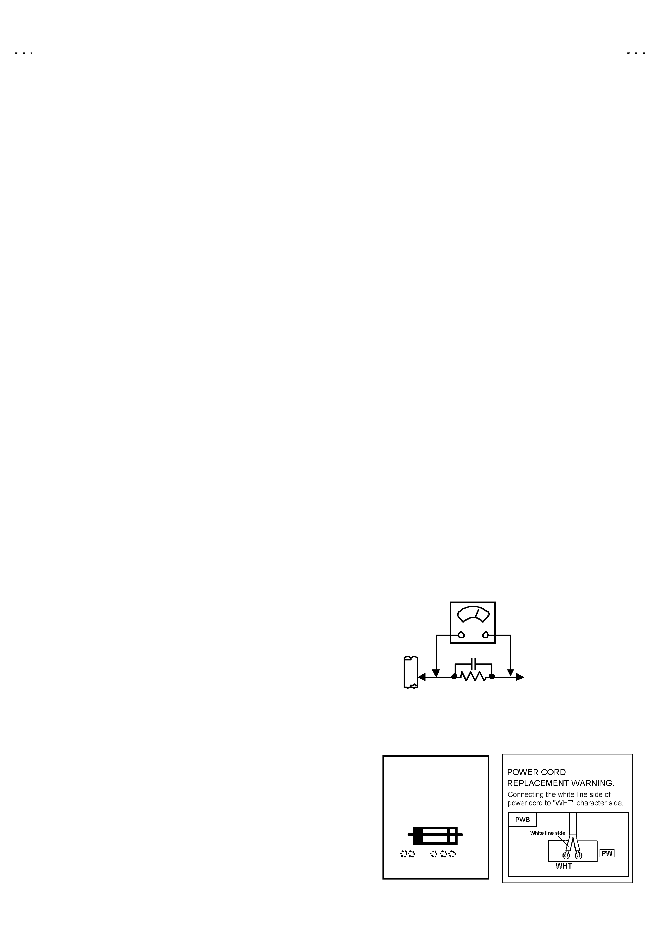
Alternate Check Method
Plug the AC line c ord directly into the AC outlet (do not use a
line isolation transformer during this check.). Use an AC
voltmeter having 1000 ohms per volt or more sensitivity in the
following manner. Connec t a 1500 10W resistor paralleled
by a 0.15 F AC-type capacitor between an exposed metal
part and a known good earth ground (water pipe, etc.).
Measure the AC voltage across the resistor with the AC
voltmeter. Move the res istor connection to each exposed metal
part, particularly any exposed metal part having a return path to
the chassis , and measure the AC voltage across the resistor.
Now, revers e the plug in the AC outlet and repeat each
measurement. Any voltage measured must not exceed 0.75V
AC (r.m.s.). This corresponds to 0.5mA AC (r.m.s.).
However, in tropic al area, this must not exceed 0.3V AC
(r.m.s.). This corresponds to 0.2mA AC (r.m.s.).
0.15F AC-TYPE
1500 10W
GOOD
EARTH
GR OUND
PLACE THIS PROBE
ON EACH EXPOSED
METAL PART
AC VOLTMETER
(HAVING 1000 /V,
OR MOR E SENSITIVITY)
11. High voltage hold down circuit check.
After repair of the high voltage hold down circuit, this circuit
shall be c hec ked to operate correctly.
See item "Ho w to check the high voltage hold down
circuit".
A
V
This mark shows a fast
operating fuse, the
letters indicated below
show the rating.
No. 51946
AV-27D503
4
FEATURES
" New chassis design enables use of a main board with simplified
circuitry.
" 3 LINE Digital Comb filter Improved pic ture quality.
" Full-square CRT (c athode ray tube) reproduc es fine textured
picture in every detail.
" With AV COMPU LINK EX terminal.
"
Closed-c aption broadcasts can be viewed.
" With AUDIO / VIDEO INPUT terminal.
"
S-VIDEO input terminal for taking best advantage of Super VHS.
" Audio output terminal.
" I2C bus control utilizes single chip ICs.
"
Becaus e built-in the BBE circ uit improved the sound of
conversation.
" DVD dec k output can inputs to c omponent video s ignal input
terminal.
" The hyper-surround system marks a reproduction of the acoustic
effects in a theater with strong appeal.
" Becaus e of built-in 2 tuner & PIP circuit, displays plural programs
on the screen at the same time.
" Built-in V-CHIP,V-CHIP CAN system
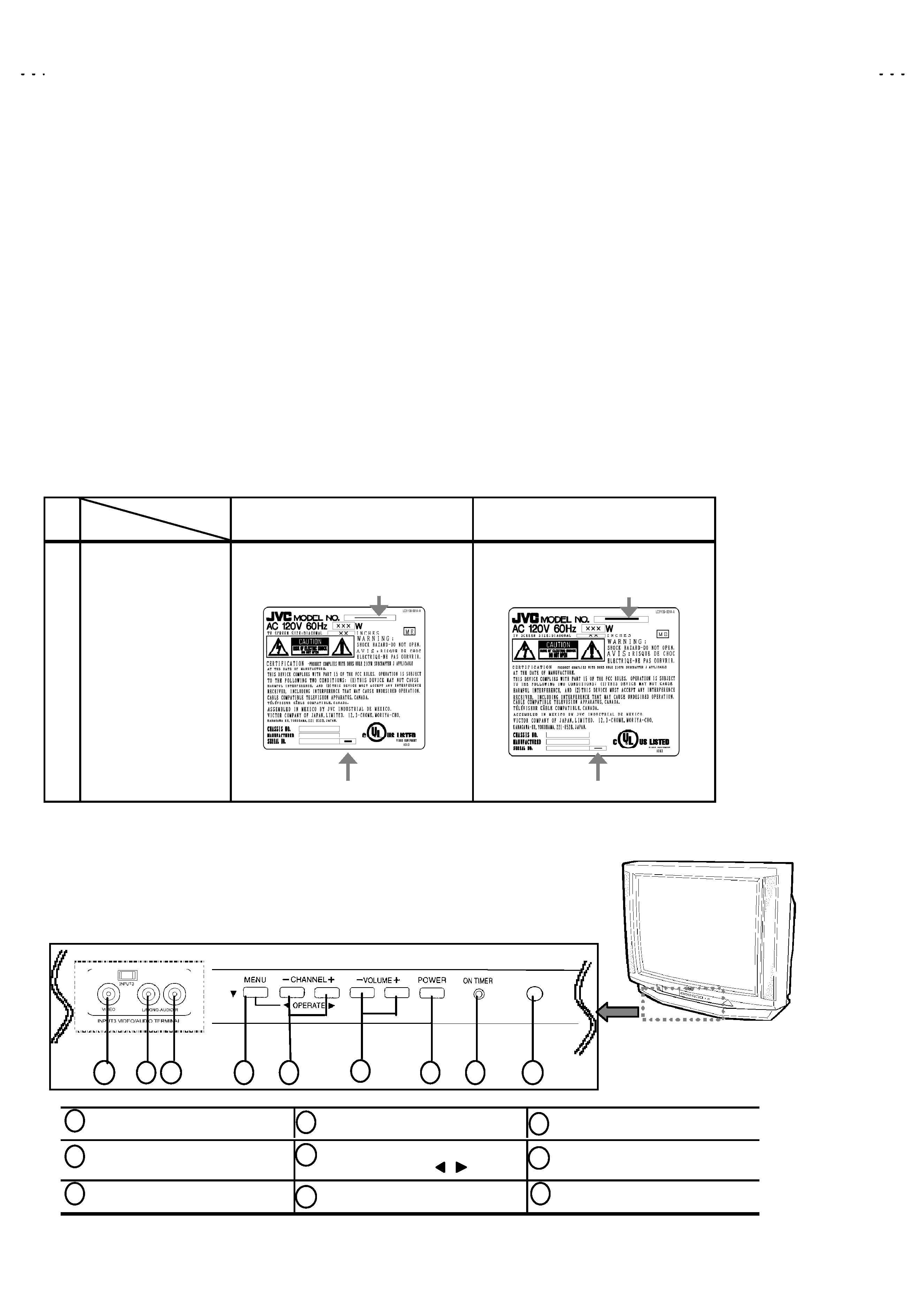
HOW TO IDENTIFY MODELS
How to recognize from the appearance of the model concerned is written below. Please distinguish from s everal
contents currently printed on the rating label
!
MODEL
Parts name
AV-27D503/S
AV-27D503/R
!
RATING LABEL
GQ30032-001A-A
INDICATED AV-27D503
INDICATED AV-27D503
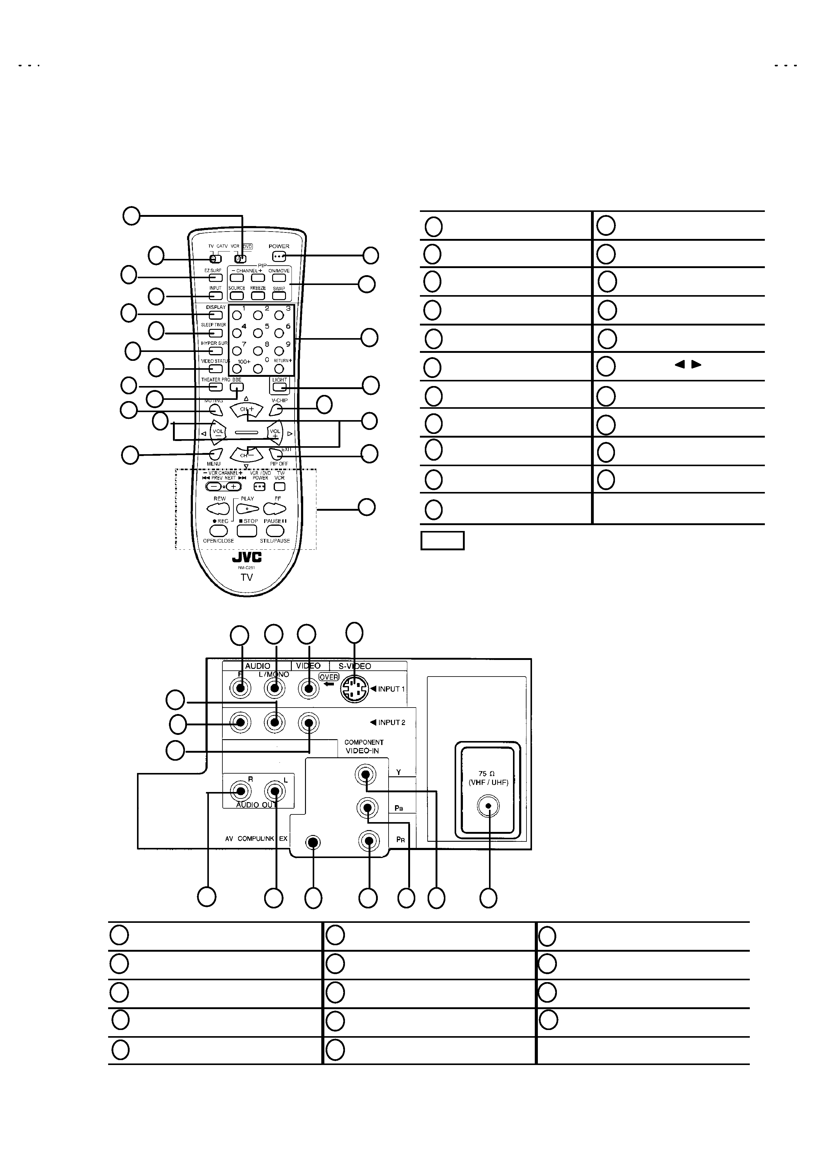
FUNCTIONS (
)
FRONT PANEL
INPUT3 VIDEO terminal
MENU button
POWER button
INPUT3 AUDIO L terminal
CHANNEL -/+ buttons
MENU OPERATE
/
buttons
ON TIMER lamp
INPUT3 AUDIO R terminal
VOLUME -/+ buttons
REMOTE CONTROL sens or
1
2
3
4
5
6
7
8
9
6
7
8
9
1
2
3
4
5
INDICATED"
"
"
"
S"
"
"
"
INDICATED"
"
"
"R"
"
"
"
No. 51946
AV-27D503
5
FUNCTIONS(
)
REMOTE CONTROL UNIT (RM-C251)
INPUT 1 AUDIO R terminal
INPUT 2 AUDIO L/MONO terminal
COMPONENT Y terminal
INPUT 1 AUDIO L/MONO terminal
INPUT 2 VIDEO terminal
COMPONENT PB terminal
INPUT 1 VIDEO terminal
AUDIO OUT R terminal
COMPONENT PR terminal
INPUT 1 S-VIDEO
AUDIO OUT L terminal
VHF / UHF terminal
INPUT 2 AUDIO R terminal
AV COMPULINK EX terminal
REAR PANEL
4
3
2
1
6
7
5
8
9
10
11
12
13
14
POWER key
MENU key
EZ SURF key
PIP keys
INPUT key
CHANNEL keys
DISPLAY key
LIGHT key
SLEEP TIMER key
V-CHIP key
HYPER SUR. key
CH/( / )keys
VIDEO STATUS key
EXIT/PIP OFF key
THEATER PRO key
VCR CONTROL key
BBE key
VCR / DVD switch
MUTING key
TV / CATV switch
VOL/(/) keys
The CH-/+ and VOL-/+ k eys operate CHANNEL and
VOLUME normally.
Thes e keys are also used to navigate MENU system.
1
1
13
14
15
16
17
18
19
9
20
21
2
3
4
5
6
7
8
10
11
12
1
8
2
9
3
10
4
11
5
12
6
13
7
14
2
3
4
5
6
7
8
9
10
11
12
13
14
15
16
18
17
19
20
21
NOTE