SERVICE MANUAL
COLOUR TELEVISION
BASIC CHASSIS
CH
No. 51848B
Sep. 2001
COPYRIGHT © 2001 VICTOR COMPANY OF JAPAN, LTD.
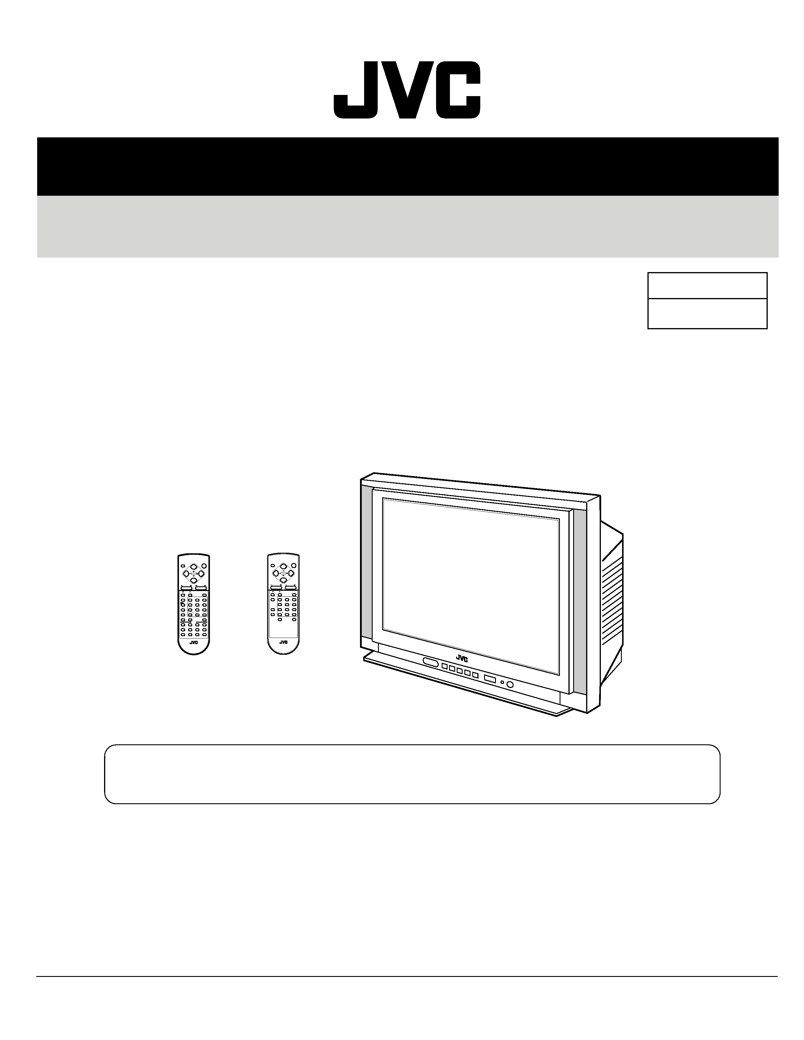
AV-25LS
AV-25LX
AV-25LS /C
AV-25LX /C
RM-C352 REMOTE CONTROL UNIT
TEXT
DISPLAY
MENU
POWER
CHANNEL
VOLUME
SYSTEM
COLOUR
REVEAL
HOLD
INDEX
STORE
MODE
SIZE
SUBPAGE
CANCEL
OFF TIMER
TV/VIDEO
PICTURE MODE
CHANNEL SCAN
TV/TEXT
ECO SENSOR
SOUND
MUTING
RETURN
I/II
123
456
78
0
9
-/--
RM-C357 REMOTE CONTROL UNIT
DISPLAY
MENU
POWER
CHANNEL
VOLUME
SYSTEM
COLOUR
OFF TIMER
TV/VIDEO
PICTURE MODE
CHANNEL SCAN
ECO SENSOR
SOUND
MUTING
RETURN
123
456
78
0
9
-/--
RM-C352-1C
[AV-25LS/C]
RM-C357-1C
[AV-25LX/C]
CONTENTS
a DIFFERENCE TABLE ..............................................................................................................................2
a SERVICE ADJUSTMENTS ......................................................................................................................3
a CIRCUIT DIAGRAMS.............................................................................................................................10
a PRINTED WIRING BOARD PARTS LIST (AV-25LS/C) .........................................................................18
a PRINTED WIRING BOARD PARTS LIST (AV-25LX/C) .........................................................................23
Regarding service information other than these sections, refer to the AV-25LS/AV-25LX service
manual (No. 51848).
Also, be sure to note important safety precautions provided in the service manual.
AV-25LS
AV-25LX
2
No. 51848B
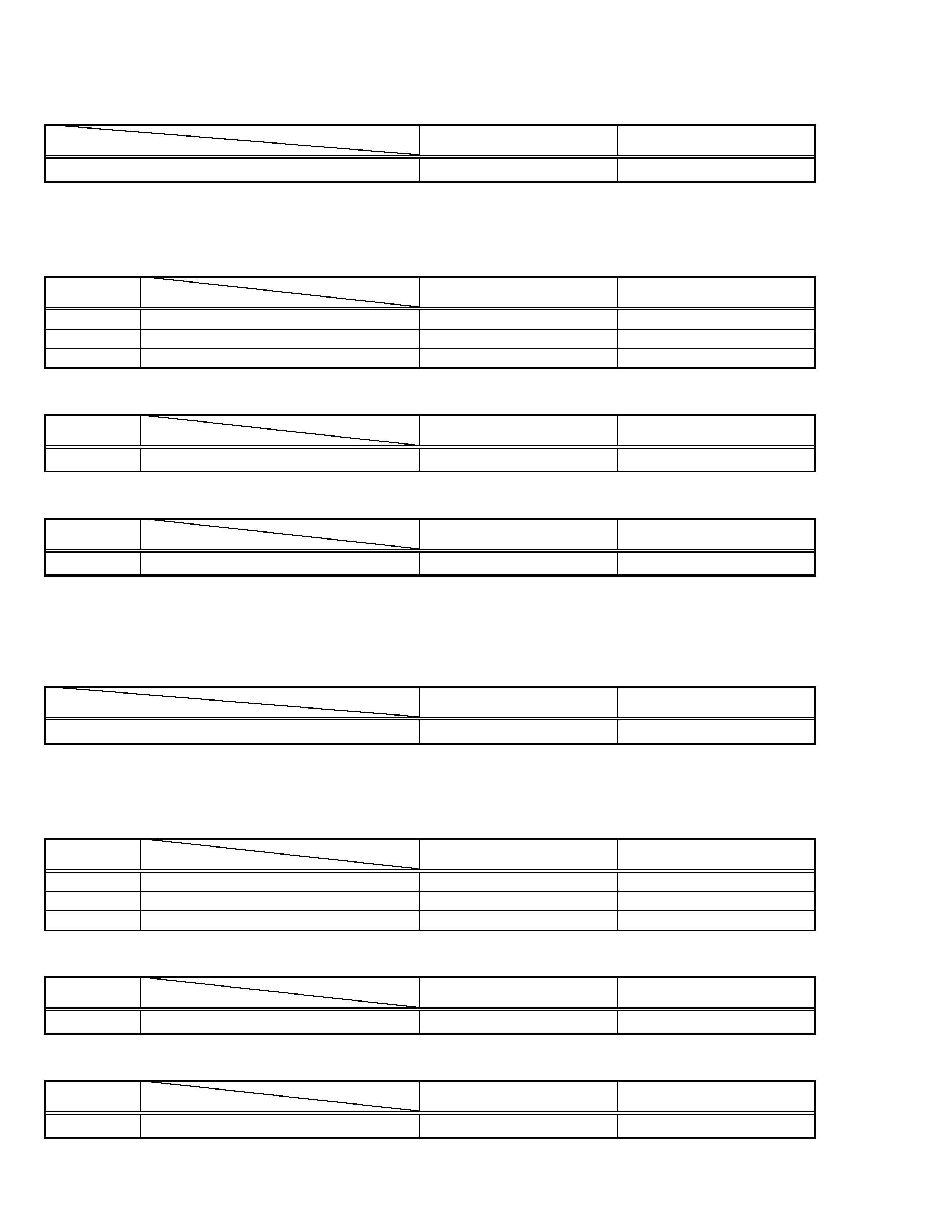
The following table indicate main different points between models AV-25LS and AV-25LS/C.
MODEL
AV-25LS
AV-25LS/C
ITEM
MASS
30kg
32kg
! REF. NO.
MODEL
AV-25LS
AV-25LS/C
ITEM
! V01
PICTURE TUBE
A59QDF891X
A60LST196X
DY01
DEFLECTION YOKE
QQD0062-001
QQD0043-001
18
FRONT CABI
GG10133-001B-H
GG10133-015A-H
EXPLODED VIEW PARTS LIST
The following table indicate different parts number between models AV-25LS and AV-25LS/C.
! REF. NO.
MODEL
AV-25LS
AV-25LS/C
ITEM
MAIN PW BOARD ASS'Y
SCH-1005A-H2
SCH-1063A-H2
PRINTED WIRING BOARD PARTS LIST
! REF. NO.
MODEL
AV-25LS
AV-25LS/C
ITEM
2
P CASE
GG10044-026A-H
GG10044-026B-H
PACKING PARTS LIST
The following table indicate main different points between models AV-25LX and AV-25LX/C.
MODEL
AV-25LX
AV-25LX/C
ITEM
MASS
30kg
32kg
! REF. NO.
MODEL
AV-25LX
AV-25LX/C
ITEM
! V01
PICTURE TUBE
A59QDF891X
A60LST196X
DY01
DEFLECTION YOKE
QQD0062-001
QQD0043-001
18
FRONT CABI
GG10133-002A-H
GG10133-014A-H
EXPLODED VIEW PARTS LIST
The following table indicate different parts number between models AV-25LX and AV-25LX/C.
! REF. NO.
MODEL
AV-25LX
AV-25LX/C
ITEM
MAIN PW BOARD ASS'Y
SCH-1006A-H2
SCH-1061A-H2
PRINTED WIRING BOARD PARTS LIST
! REF. NO.
MODEL
AV-25LX
AV-25LX/C
ITEM
2
P CASE
GG10044-026A-H
GG10044-026B-H
PACKING PARTS LIST
AV-25LS
AV-25LX
No. 51848B
3
SERVICE ADJUSTMENTS
VC (VIDEO/CHROMA) CIRCUIT ADJUSTMENT
The setting (adjustment) using the remote control unit is made on the basis of the initial setting values.
The setting values which adjust the screen to the optimum condition can be different from the initial setting values.
· Do not change the initial setting values of the setting (adjustment) items not listed in"ADJUSTMENT".
[SUB MENU 2. VC]
: Do not adjust.
Setting (Adjustment) item
Variable range
Initial setting value
PAL
SECAM
NTSC3.58
NTSC4.43
COMPONENT
1
CUTOFF(R/G)
7 -- +8
0
2
DRIVE(R/G/B)
30 -- +31
0
3
BRIGHT(COM./TV/V-1/V-2/V-3)
30 -- +31
0/18/0/0/0
4
CONT
30 -- +31
20
--
5
COLOUR
30 -- +31
5
3
12
6
+10
6
TINT (TV/VIDEO)
30 -- +31
--
--
15/+4
+1/+1
--
7
SHARP (TV/VIDEO)
30 -- +31
16/2
--/0
8
YDELAY (TV/VIDEO)
8 -- +7
0/+1
+5/+1
0/+1
+5/0
--
Item
Measuring
instrument
Test point
Adjustment part
Description
Adjustment
of WHITE
BALANCE
(Low light)
1. CUTOFF (R)
CUTOFF (G)
SCREEN VR
[In HVT]
Note:
· Set PICTURE MODE (VSM) to "BRIGHT".
1. Receive a PAL black and white signal (colour off).
2. Select 2. VC from the SERVICE MENU.
3. Select 1. CUTOFF (R) and (G) with MENU &/^ key, and set each
value to initial setting value with the 4 and 7 keys, or 5 and 8 keys on
the remote control unit.
4. Press the 1 key on the remote control unit to produce a single hori-
zontal line.
5. Turn the SCREEN VR fully counterclockwise, then slowly turn it clock-
wise to where a red, blue or green colour is faintly visible.
6. Use the keys 4 and 7 or 5 and 8 on the remote control unit and
adjust the other 2 colours to where the single horizontal line ap-
pears white.
7. Turn the SCREEN VR to where the single horizontal line glows faintly.
8. Press the 2 key to return to 1. CUTOFF screen.
9. Press the DISPLAY key twice to return to the normal screen.
Setting (Adjustment)
Variable
Initial setting
Item
range
value
1. CUT OFF
R
7 -- +8
0
G
7 -- +8
0
PAL
1. CUTOFF
50 Hz
(R)
(G)
**
**
V/C
MENU 89: SELECT
MENU - / + : OPERATE
DISPLAY : EXIT
Signal
generator
Remote
control unit
G. CUTOFF (8)
H.LINE OFF
H.LINE ON
12
3
4
78
9
56
R. CUTOFF (8)
R. CUTOFF (9)
G.CUTOFF (9)
REMOTE CONTROL UNIT
AV-25LS
AV-25LX
4
No. 51848B
Item
Measuring
instrument
Test point
Adjustment part
Description
Adjustment
of
SUB
COLOUR-I
Remote
control unit
[Method of adjustment without measuring instrument]
Notes:
· Proceed to the following this adjustment after having completed the
adjustment of SUB CONT.
· Set PICTURE MODE (VSM) to "BRIGHT".
PAL COLOUR
1. Receive a PAL broadcast.
2. Select 2. VC from the SERVICE MENU.
3. Select 5. COLOUR with the MENU &/^ key.
4. Set the initial setting value for PAL COLOUR with the MENU /+ key.
5. If the colour is not best with the initial setting value, make fine ad-
justment until you get the best colour.
6. Press the DISPLAY key twice to return to the normal screen.
SECAM COLOUR
7. Receive a SECAM broadcast.
8. Press the COLOUR SYSTEM button on the remote control unit to
select the SECAM colour system.
9. Make fine adjustment of SECAM COLOUR in the same way as for
"PAL COLOUR".
NTSC 3.58 COLOUR
10. Receive a NTSC 3.58MHz broadcast.
11. Press the COLOUR SYSTEM button on the remote control unit to
select the NTSC 3.58 colour system.
12. Make similar fine adjustment of NTSC 3.58 COLOUR in the same
way as for "PAL COLOUR".
NTSC 4.43 COLOUR
When adjustment is done for NTSC 3.58 COLOUR, appropriate
values are automatically set for NTSC 4.43 COLOUR.
5. COLOUR
Adjustment
of SUB
COLOUR-II
Signal
generator
Oscilloscope
Remote
control unit
5. COLOUR
[Method of adjustment using measuring instrument]
Notes:
· Proceed to the following this adjustment after having completed the
adjustment of SUB CONT.
· Set PICTURE MODE (VSM) to "BRIGHT".
PAL COLOUR
1. Receive a PAL colour bar signal (full field colour bar 75% white).
2. Select 2. VC from the SERVICE MENU.
3. Select 5. COLOUR with the MENU &/^ key.
4. Set the initial setting value of PAL COLOUR with the MENU /+ key.
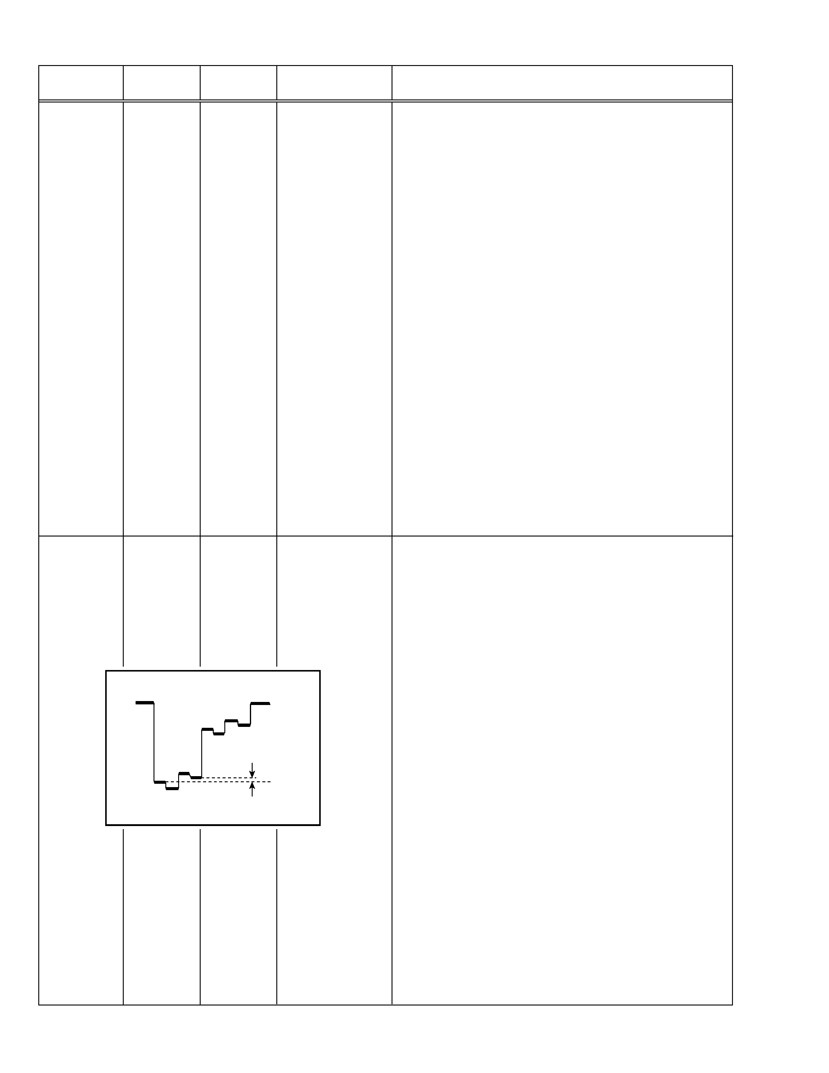
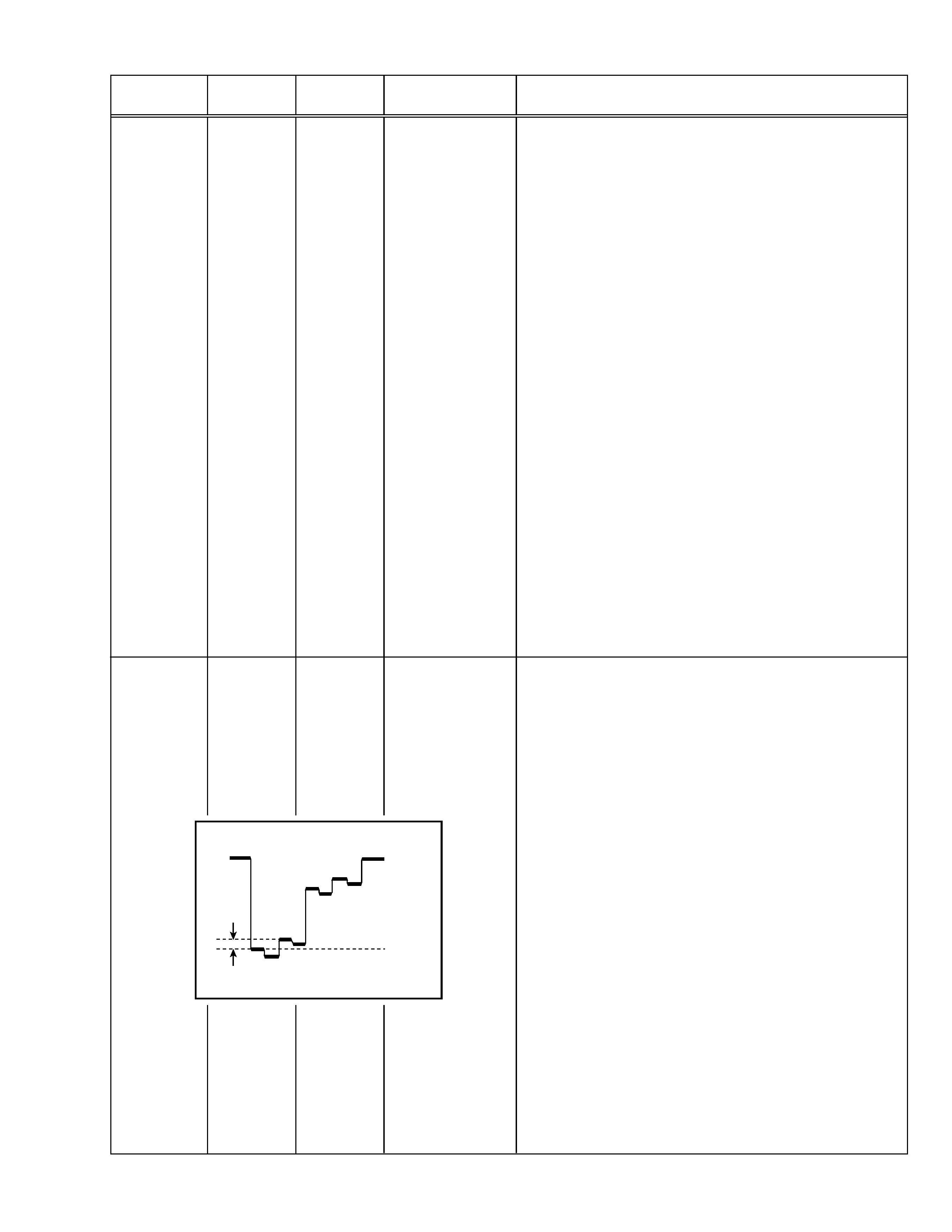
5. Connect the oscilloscope between TP-47G and TP-E.
6. Adjust PAL COLOUR to set the value (A) in the figure to +14V (VW-G).
SECAM COLOUR
7. Receive a SECAM colour bar signal (full field colour bar 75% white).
8. Press the COLOUR SYSTEM button on the remote control unit to
select the SECAM colour system.
9. Set the initial setting value of SECAM COLOUR with the MENU /+ key.
10. Adjust SECAM COLOUR to set the value (A) in the figure to 3V
(VW-G).
NTSC 3.58 COLOUR
11. Receive a NTSC 3.58 colour bar signal (full field colour bar 75% white).
12. Press the COLOUR SYSTEM button on the remote control unit to
select the NTSC 3.58 colour system.
13. Set the initial setting value of NTSC 3.58 COLOUR with the MENU
/+ key.
14. Adjust NTSC 3.58 COLOUR to set the value (A) in the figure to
+3V (VW-G).
NTSC 4.43 COLOUR
When adjustment is done for NTSC 3.58 COLOUR, appropriate
values are automatically set for NTSC 4.43 COLOUR.
TP-47G
TP-E (
H)
[CRT
SOCKET
PWB]
Mg
B
()
0V
(+)
R
Cy
Y
W
G
(A)
AV-25LS
AV-25LX
No. 51848B
5
Item
Measuring
instrument
Test point
Adjustment part
Description
Adjustment
of
SUB TINT-I
Remote
control unit
6. TINT
[Method of adjustment without measuring instrument]
Notes:
· Proceed to the following this adjustment after having completed the
adjustment of SUB CONT.
· Set PICTURE MODE (VSM) to "BRIGHT".
NTSC 3.58 TINT
1. Receive a NTSC 3.58 colour bar signal (full field colour bar 75%
white).
2. Press the COLOUR SYSTEM button on the remote control unit to
select the NTSC 3.58 colour system.
3. Select 2. VC from the SERVICE MENU.
4. Select 6. TINT with the MENU &/^ key.
5. Set the initial setting value of NTSC 3.58 with the MENU /+ key.
6. If you cannot get the best tint with the initial setting value, make fine
adjustment until you get the best tint.
7. Press the DISPLAY key twice to return to the normal screen.
NTSC 4.43 TINT
When adjustment is done for NTSC 3.58 TINT, appropriate values are
automatically set for NTSC 4.43 TINT.
Mg
B
()
0V
(+)
R
Cy
Y
W
(B)
G
Adjustment
of SUB
SUB TINT-II
Signal
generator
Oscilloscope
Remote
control unit
6. TINT
[Method of adjustment using measuring instrument]
Notes:
· Proceed to the following this adjustment after having completed the
adjustment of SUB CONT.
· Set PICTURE MODE (VSM) to "BRIGHT".
NTSC 3.58 TINT
1. Receive a NTSC 3.58 colour bar signal (full field colour bar 75%
white).
2. Press the COLOUR SYSTEM button on the remote control unit to
select the NTSC 3.58 colour system.
3. Select 2. VC from the SERVICE MENU.
4. Select 6. TINT with the MENU &/^ key.
5. Set the initial setting value of NTSC 3.58 with the MENU /+ key.
6. Connect the oscilloscope between TP-47G and TP-E.
7. Adjust NTSC 3.58 TINT to set the value (B) in the figure to +3V (VW-cy).
8. Press the DISPLAY key twice to return to the normal screen.
NTSC 4.43 TINT
When adjustment is done for NTSC 3.58 TINT, appropriate values are
automatically set for NTSC 4.43 TINT.
TP-47G
TP-E (
H)
[CRT
SOCKET
PWB]