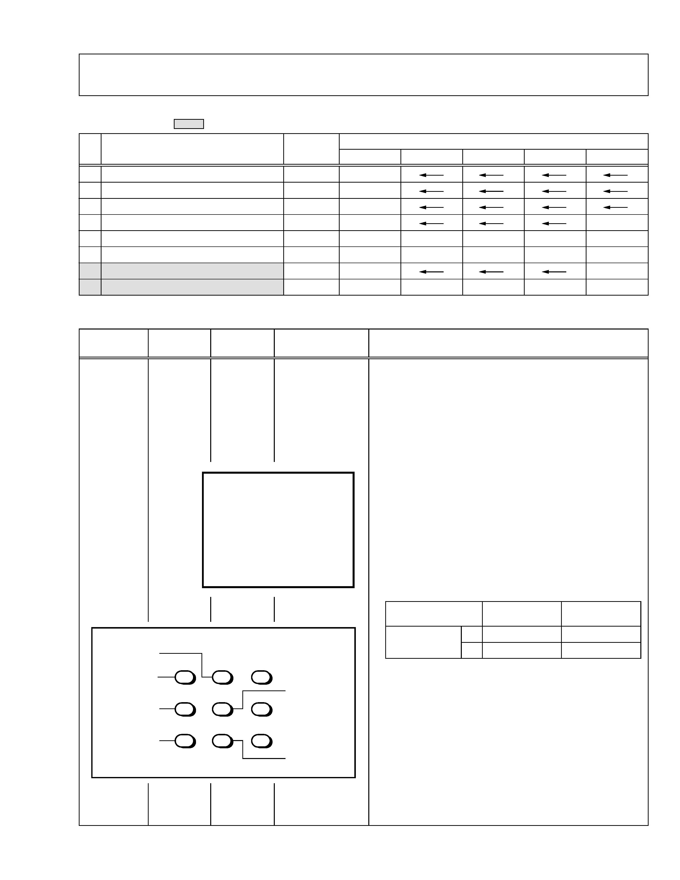
SERVICE MANUAL
COLOUR TELEVISION
BASIC CHASSIS
CH
No. 51849B
Sep. 2001
COPYRIGHT © 2001 VICTOR COMPANY OF JAPAN, LTD.
AV-21LS
AV-21LX
AV-21LS /C
AV-21LX /C
RM-C352 REMOTE CONTROL UNIT
TEXT
DISPLAY
MENU
POWER
CHANNEL
VOLUME
SYSTEM
COLOUR
REVEAL
HOLD
INDEX
STORE
MODE
SIZE
SUBPAGE
CANCEL
OFF TIMER
TV/VIDEO
PICTURE MODE
CHANNEL SCAN
TV/TEXT
ECO SENSOR
SOUND
MUTING
RETURN
I/II
123
456
78
0
9
-/--
RM-C357 REMOTE CONTROL UNIT
DISPLAY
MENU
POWER
CHANNEL
VOLUME
SYSTEM
COLOUR
OFF TIMER
TV/VIDEO
PICTURE MODE
CHANNEL SCAN
ECO SENSOR
SOUND
MUTING
RETURN
123
456
78
0
9
-/--
RM-C352-1C
[AV-21LS/C]
RM-C357-1C
[AV-21LX/C]
CONTENTS
a DIFFERENCE TABLE ..............................................................................................................................2
a SERVICE ADJUSTMENTS ......................................................................................................................3
a CIRCUIT DIAGRAMS.............................................................................................................................22
a PRINTED WIRING BOARD PARTS LIST (AV-21LS/C) .........................................................................30
a PRINTED WIRING BOARD PARTS LIST (AV-21LX/C) .........................................................................35
Regarding service information other than these sections, refer to the AV-21LS/AV-21LX service
manual (No. 51849).
Also, be sure to note important safety precautions provided in the service manual.
AV-21LS
AV-21LX
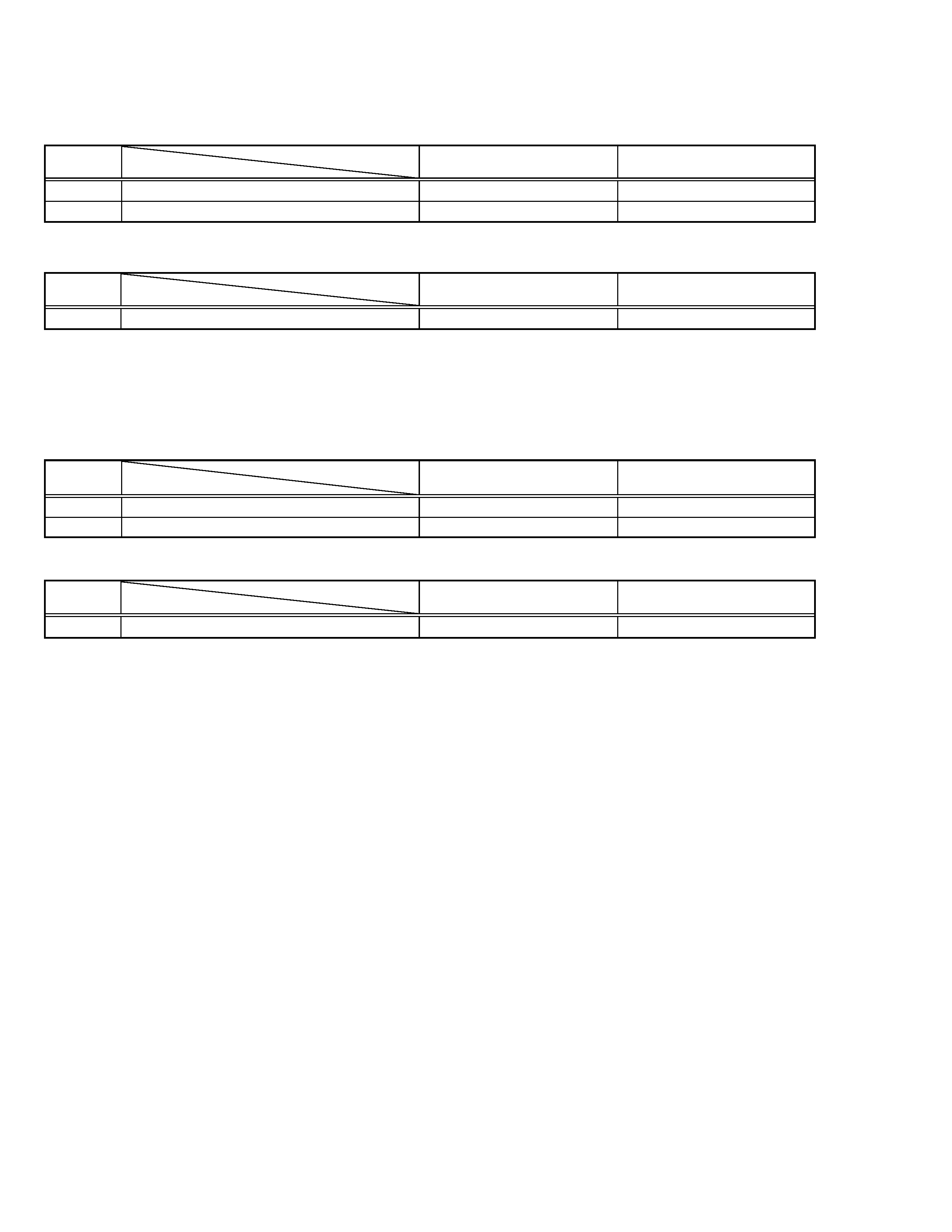
The following table indicate different parts number between models AV-21LS and AV-21LS/C.
!
REF.
MODEL
AV-21LS
AV-21LS/C
NO.
ITEM
! V01
PICTURE TUBE
A51QDX992X
A51LSH196X
DY01
DEFLECTION YOKE
QQD0060-002
QQD0044-001
EXPLODED VIEW PARTS LIST
!
REF.
MODEL
AV-21LS
AV-21LS/C
NO.
ITEM
MAIN PW BOARD ASS'Y
SCH-1003A-H2
SCH-1062A-H2
PRINTED WIRING BOARD PARTS LIST
The following table indicate different parts number between models AV-21LX and AV-21LX/C.
!
REF.
MODEL
AV-21LX
AV-21LX/C
NO.
ITEM
! V01
PICTURE TUBE
A51QDX992X
A51LSH196X
DY01
DEFLECTION YOKE
QQD0060-002
QQD0044-001
!
REF.
MODEL
AV-21LX
AV-21LX/C
NO.
ITEM
MAIN PW BOARD ASS'Y
SCH-1004A-H2
SCH-1060A-H2
PRINTED WIRING BOARD PARTS LIST
2
No. 51849B
EXPLODED VIEW PARTS LIST
AV-21LS
AV-21LX
No. 51849B
3
SERVICE ADJUSTMENTS
ADJUSTMENT PREPARATION:
1. You can make the necessary adjustments for this unit with either the remote control unit or with the adjustment equipment and parts
as given below.
2. Adjustment with the remote control unit is made on the basis of the initial setting values, however, the new setting values which set the
screen to its optimum condition may differ from the initial settings.
3. Make sure that AC power is turned on correctly.
4. Turn on the power for the set and test equipment before use, and start the adjustment procedures after waiting at least 30 minutes.
5. Unless otherwise specified, prepare the most suitable reception or input signal for adjustment.
6. Never touch any adjustment parts, which are not specified in the list for this adjustment-variable resistors, transformers, capacitors, etc.
7. Presetting before adjustment.
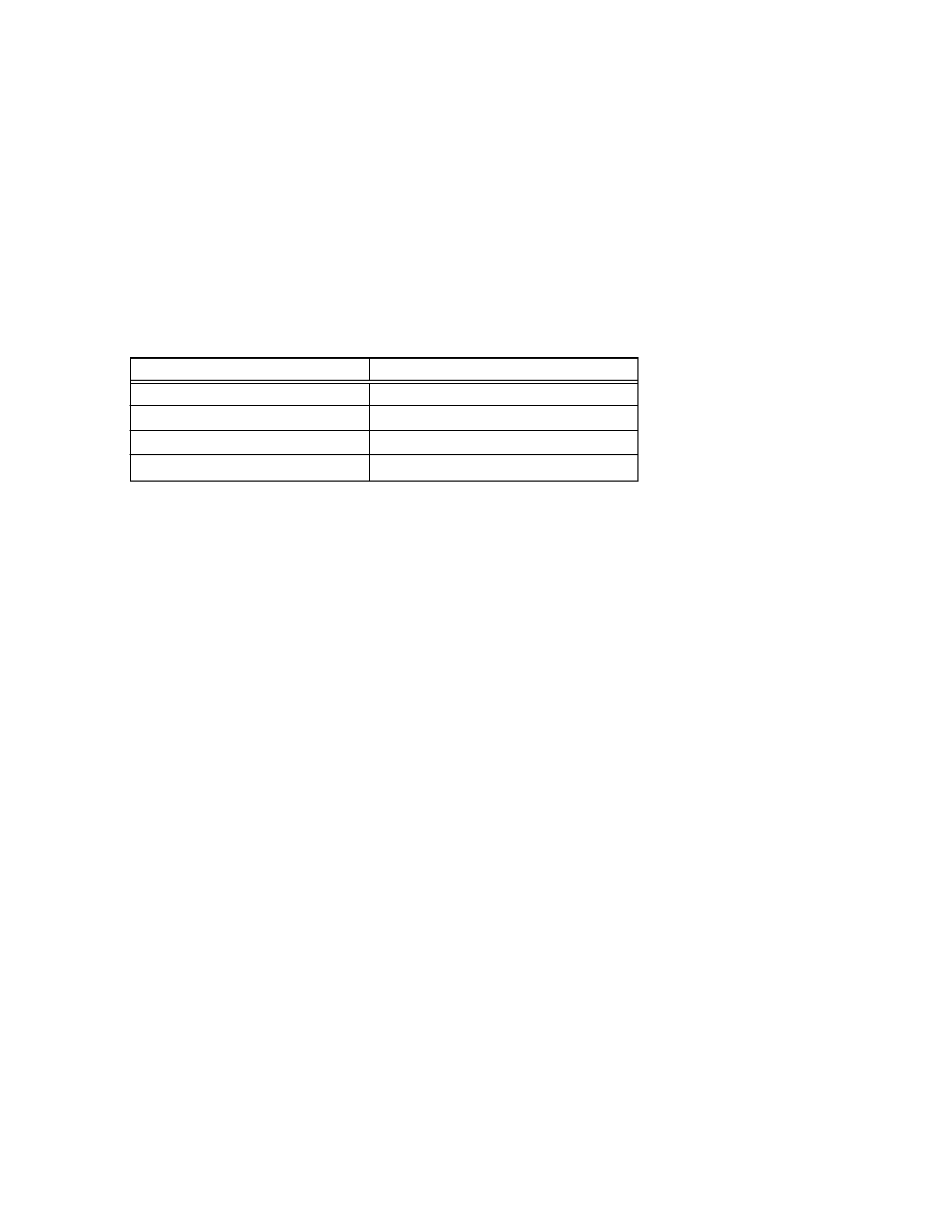
Unless otherwise specified in the adjustment instructions, preset the following functions with the remote control unit.
Setting item
Setting value
PICTURE MODE(VSM)
BRIGHT
VNR
OFF
BASS,TREBLE,BALANCE
CENTRE
TINT,COLOUR,BRIGHT,CONT,SHARP
CENTRE
MEASURING INSTRUMENT
1. DC voltmeter (or Digital voltmeter)
2. Oscilloscope
3. Signal generator (Pattern generator) [PAL/SECAM/NTSC]
4. Remote control unit
ADJUSTMENT ITEMS
· B1 POWER SUPPLY
· FOCUS adjustment
· IF circuit adjustment
VCO (CW) adjustment
DELAY POINT adjustment
· VC (VIDEO/CHROMA) circuit adjustment
WHITE BALANCE (Low light) adjustment
WHITE BALANCE (High light) adjustment
SUB BRIGHT adjustment
SUB CONT adjustment
SUB COLOUR adjustment
SUB TINT adjustment
· DEFLECTION circuit adjustment
VER. SLOPE adjustment
VER. POSITION adjustment
V. ZOOM adjustment
HOR. POSITION adjustment
HOR. WIDTH adjustment
EW-PIN adjustment
EW-TRAPEZ adjustment
VER. SCURVE adjustment
UP CORNER and DW CORNER adjustment
HOR. PARALL adjustment
HOR. BOW adjustment
· User mode setting position
· VSM PRESET adjustment
· PRESET adjustment
· AUDIO ADJUSTMENT [AV-21LS/C]
· PURITY and CONVERGENCE adjustments
PURITY adjustment
STATIC CONVERGENCE adjustment
DYNAMIC CONVERGENCE adjustment
4
No. 51849B
AV-21LS
AV-21LX
ADJUSTMENTS
Item
Measuring
instrument
Test point
Adjustment part
Description
Check of
B1 POWER
SUPPLY
Signal
Generator
DC Voltmeter
B1 (pin 1)
GND (pin 5)
[CN00S
connector]
1. Receive a black and white signal.
2. Connect a DC voltmeter between B1 and GND
(between pins 1 and 5 of the connector CN00S).
3. Make sure that the voltage is DC135 ± 2V.
Adjustment
of FOCUS
FOCUS VR
[In HVT]
Item
Measuring
instrument
Test point
Adjustment part
Description
FOCUS ADJUSTMENT
B1 POWER SUPPLY
Signal
generator
Notes:
· Set PICTURE MODE (VSM) to "BRIGHT".
· The final adjustment of CONVERGENCE must be done after the
FOCUS adjustment. (CONVERGENCE is changed by FOCUS ad-
justment.)
When makes difference by FOCUS adjustment, should be reconfirming
PURITY adjustment.
1. Receive a cross-hatch signal.
2. While looking at the screen centre, adjust the FOCUS VR so that
the vertical and horizontal lines will be clear and in fine detail.
3. Make sure that the picture is in focus even when the screen gets
darkened.
Adjustment
of VCO (CW)
VCO (CW)
Item
Measuring
instrument
Test point
Adjustment part
Description
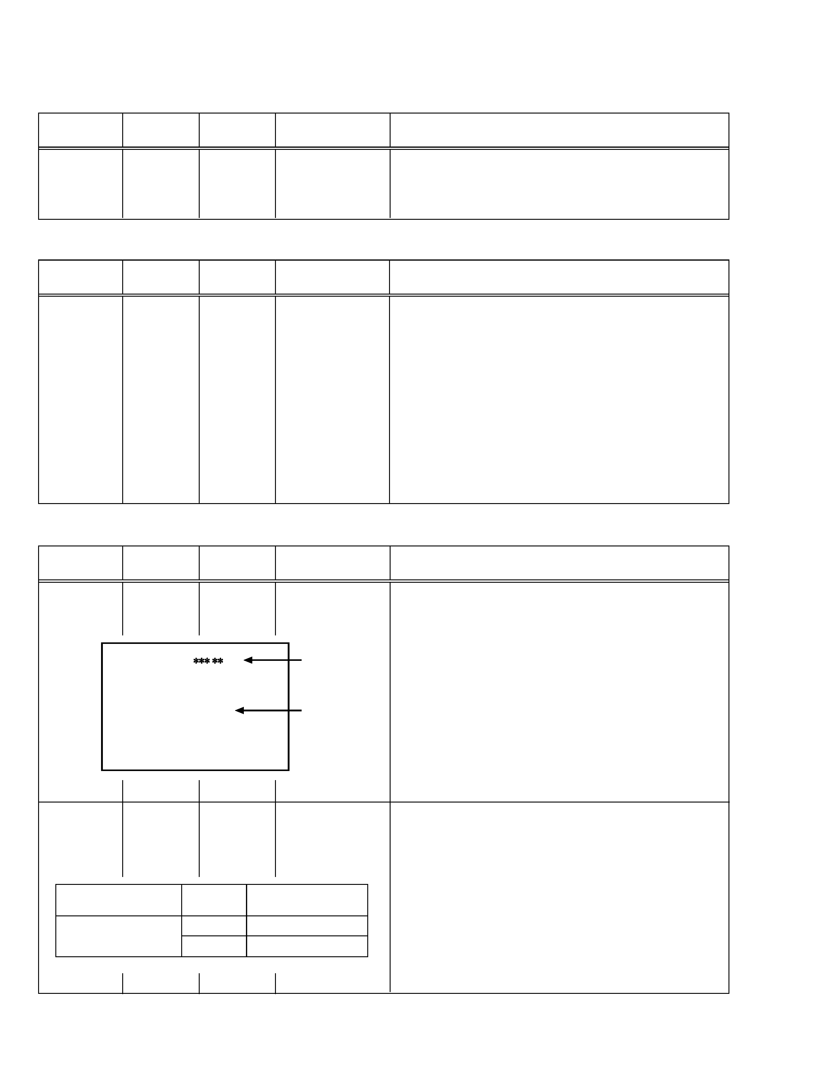
IF CIRCUIT ADJUSTMENT
Remote
control unit
Note:
· Under normal conditions, no adjustment is required.
1. Select 1. IF from the SERVICE MENU.
2. Select 1. VCO by pressing the 1 key on the remote control unit.
3. Receive a broadcast signal.
4. Check the characters colour of the BELOW REFERENCE displayed
to yellow.
5. Press the DISPLAY key three times to return to normal screen.
TOO HIGH
ABOVE REFERENCE
BELOW REFERENCE
TOO LOW
VCO (CW)
.
MHz
DISPLAY : EXIT
fv
YELLOW
Adjustment
of DELAY
POINT
DELAY POINT
(AGC TAKE-OVER)
Remote
control unit
1. Receive a black and white broadcast signal (colour off).
2. Select 1. IF from the SERVICE MENU.
3. Select 2. DELAY POINT by pressing the 2 key on the remote con-
trol unit.
4. Adjust the MENU /+ key in order to eliminate any noise or beat
from the image. Any increase above the initial value produces noise
and any decrease below it produces beat.
5. Press the DISPLAY key three times to return to the normal screen.
6. Turn to other channels and make sure that there are no irregulari-
ties.
Setting
Initial setting value
(Adjustment time)
DELAY POINT
NTSC 3.58
17
(AGC TAKE-OVER)
OTHERS
15
AV-21LS
AV-21LX
No. 51849B
5
VC (VIDEO/CHROMA) CIRCUIT ADJUSTMENT
The setting (adjustment) using the remote control unit is made on the basis of the initial setting values.
The setting values which adjust the screen to the optimum condition can be different from the initial setting values.
· Do not change the initial setting values of the setting (adjustment) items not listed in"ADJUSTMENT".
[SUB MENU 2. VC]
: Do not adjust.
Setting (Adjustment)
Variable range
Initial setting value
item
PAL
SECAM
NTSC3.58
NTSC4.43
COMPONENT
Item
Measuring
instrument
Test point
Adjustment part
Description
Adjustment
of WHITE
BALANCE
(Low light)
1. CUTOFF (R)
CUTOFF (G)
SCREEN VR
[In HVT]
Note:
· Set PICTURE MODE (VSM) to "BRIGHT".
1. Receive a PAL black and white signal (colour off).
2. Select 2. VC from the SERVICE MENU.
3. Select 1. CUTOFF (R) and (G) with MENU &/^ key, and set each
value to initial setting value with the 4 and 7 keys, or 5 and 8 keys on
the remote control unit.
4. Press the 1 key on the remote control unit to produce a single hori-
zontal line.
5. Turn the SCREEN VR fully counterclockwise, then slowly turn it clock-
wise to where a red, blue or green colour is faintly visible.
6. Use the keys 4 and 7 or 5 and 8 on the remote control unit and
adjust the other 2 colours to where the single horizontal line ap-
pears white.
7. Turn the SCREEN VR to where the single horizontal line glows faintly.
8. Press the 2 key to return to 1. CUTOFF screen.
9. Press the DISPLAY key twice to return to the normal screen.
Setting (Adjustment)
Variable
Initial setting
Item
range
value
1. CUT OFF
R
7 -- +8
0
G
7 -- +8
0
PAL
1. CUTOFF
50 Hz
(R)
(G)
**
**
V/C
MENU 89: SELECT
MENU - / + : OPERATE
DISPLAY : EXIT
Signal
generator
Remote
control unit
G. CUTOFF (8)
H.LINE OFF
H.LINE ON
12
3
4
78
9
56
R. CUTOFF (8)
R. CUTOFF (9)
G.CUTOFF (9)
REMOTE CONTROL UNIT
1
CUTOFF (R/G)
-7 +8
0
2
DRIVE (R/G/B)
-30 +31
0
3
BRIGHT (COM./TV/V-1/V-2/V-3)
-30 +31
0/-18/0/0/0
4
CONT
-30 +31
-20
--
5
COLOUR
-30 +31
-5
-3
-12
-2
+10
6
TINT (TV/VIDEO)
-30 +31
----
-15/+4
+1/+1
--
7
SHARP (TV/VIDEO)
-30 +31
-16/-2
--/0
8
YDELAY (TV/VIDEO)
-8 +7
0/+1
+5/+1
0/+1
+5/0
--