No.56013C
Sept. 2001
AV-21AT
1
COPYRIGHT © 2001 VICTOR COMPANY OF JAPAN, LTD.
AV-21AT/c
OUTLINE
HOW TO IDENTIFY MODELS
DIFFERENCE LIST
USING PW BOARD (Page 28)
Model
PWB A'SSY
AV-21AT
AV-21AT/c
Remark
MAIN PWB
SCG-1247A-H2
SCG-1242A-H2
Not interchangeable
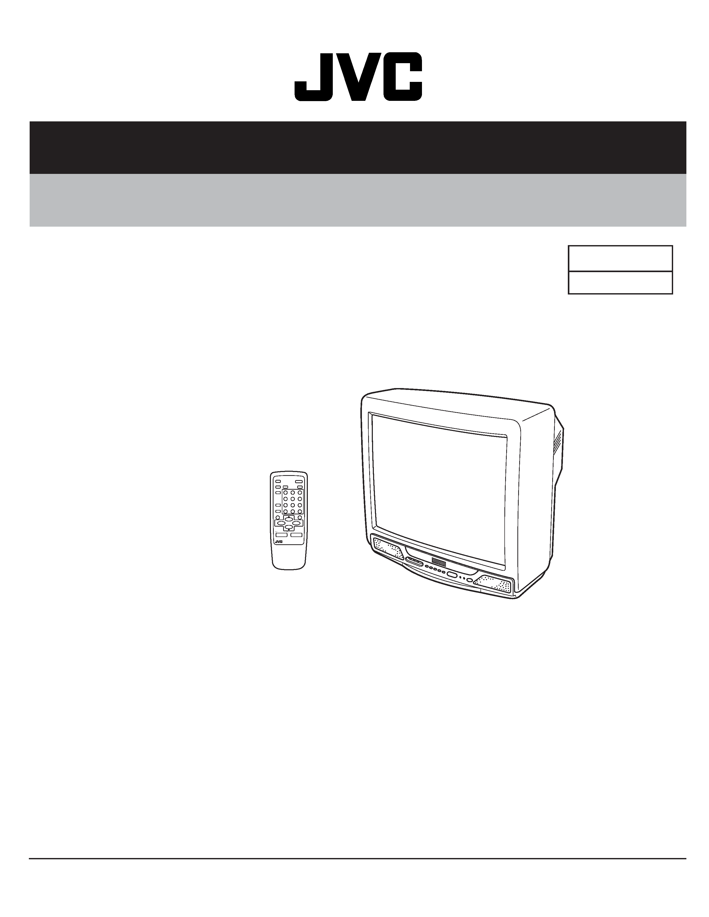
SERVICE MANUAL
COLOUR TELEVISION
BASIC CHASSIS
CG
The following item for the AV-21AT/c model was changed partly from AV-21AT model. Therefore,
this service manual describes only the items which differ from those of the AV-21AT service
manual.
For details other than those described in this manual, please refer to the AV-21AT service manual
(No.56013. 2000).
Since the picture tube was changed, we have issued the SERVICE MANUAL for AV-21AT/c.
Supplement
Identify that the model name "AV-21AT/c" is printed on the margin of the rating label affixed to the
rear cover.
21ATC-H
#999
4
Printed in Japan
VP 0109
DP2051
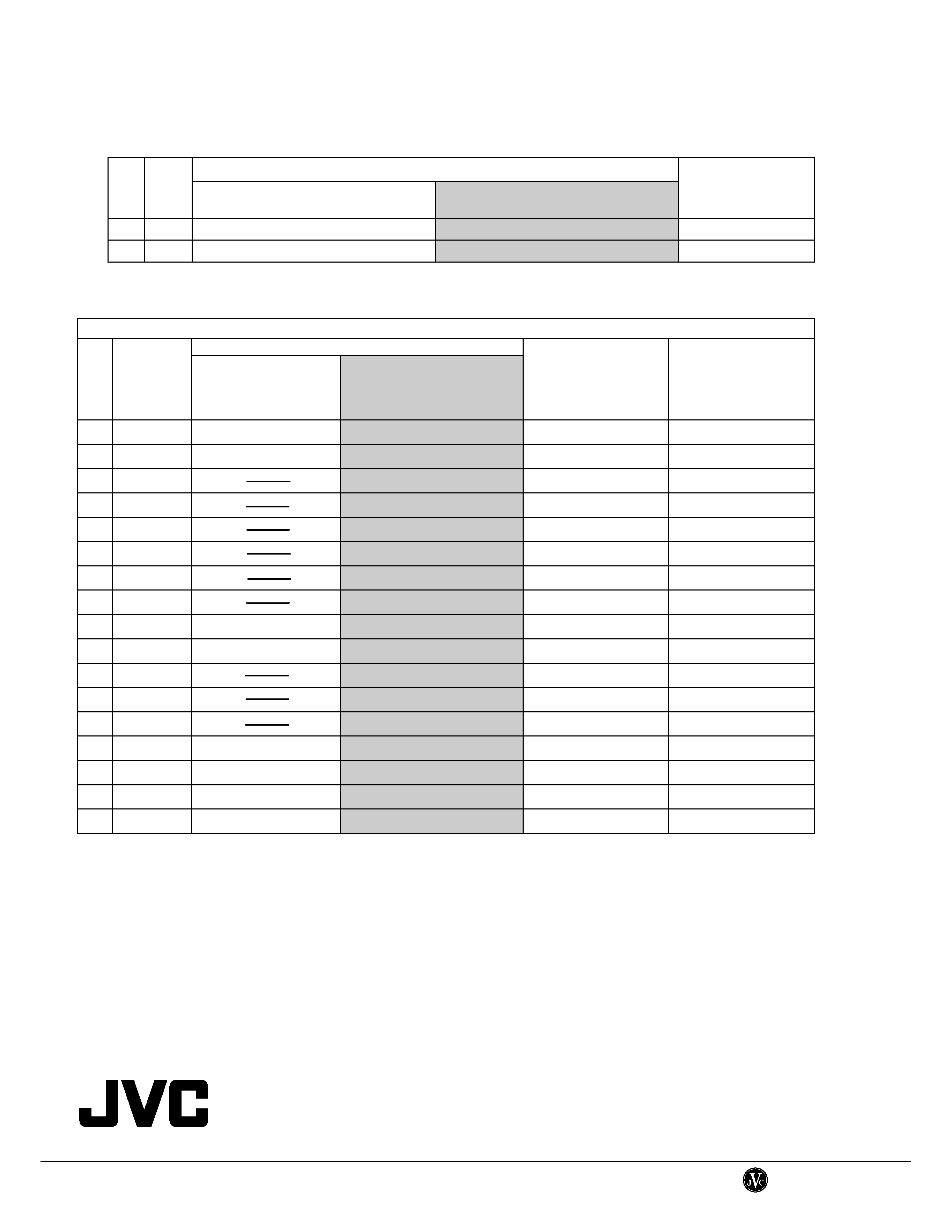
EXPLODED VIEW PARTS LIST (Page 28)
Parts No.
!
!
!
!
Ref.
No.
AV-21AT
AV-32WFR1EKS C
Parts Name
!
V01
A51LMV20X
A51LEC065X
PICTURE TUBE
!
DY01
CE20336-00A
CE20332-00A
DEF YOKE
PRINTED WIRING BOARD PARTS LIST
POWER & DEF. PW BOARD A'SSY (Page 30~32)
Parts No.
!
!
!
!
Symbol
No.
SCG-1247A-H2
(AV-21AT)
SCG-1242A-H2
(AV-21AT/c)
Parts Name
Description
R1103
NRSA02J-100X
NRSA02J-820X
CH MG R
82 1/10W
J
R1112
NRSA02J-100X
NRSA02J-220X
CH MG R
22 1/10W
J
R1161
NRSA02J-102X
CH MG R
1K 1/10W
J
R1162
NRSA02J-102X
CH MG R
1.2K 1/10W
J
R1163
NRSA02J-122X
CH MG R
2.2K 1/10W
J
R1164
NRSA02J-221X
CH MG R
220 1/10W
J
R1165
NRSA02J-220X
CH MG R
22 1/10W
J
R1166
NRSA02J-821X
CH MG R
820 1/10W
J
R1531
NRSA02J-472Y
NRSA02J-103X
CH MG R
10K 1/10W
J
R1554
QRE121J-681Y
QRE121J-821Y
CR
820 1/2W
J
C1161
NCB31HK-103X
CH C CAP
0.01F 50V
K
C1164~65
NCB31HK-103X
CH C CAP
0.01F 50V
K
C1166
NCB21HK-104X
CH C CAP
0.1F 50V
K
C1525
QFZ0200-103
QFZ0200-962
MPP CAP
9600pF 1.5kVH ±3%
C1527
QFZ0199-334
QFZ0199-254
MPP CAP
0.25F 250V
J
C1582
QFZ0199-104
QFZ0199-274
MPP CAP
0.27F 250V
J
L1551
QQLZ018-380
QQLZ034-540
HETER CHOKE
VICTOR COMPANY OF JAPAN, LIMITED
HOME AV NETWORK BUSINESS UNIT
12, 3-chome, Moriya-cho, Kanagawa-ku, Yokohama, Kanagawa-prefecture, 221-8528, Japan
AV-21AT
No. 56013
1
BASIC CHASSIS
CG
SERVICE MANUAL
COLOUR TELEVISION
AV-21AT
AV-21AT
COPYRIGHT
© 2000 VICTOR COMPANY OF JAPAN, LTD.
No. 56013
May 2000
+
-
+
-
CONTENTS
s SPECIFICATIONS ........................................................................................................................... 2
s SAFETY PRECAUTIONS ................................................................................................................ 3
s FEATURES ...................................................................................................................................... 4
5 OPERATING INSTRUCTIONS (APPENDED) .............................................................................. 1-1
s SPECIFIC SERVICE INSTRUCTIONS ............................................................................................ 4
s SERVICE ADJUSTMENTS ............................................................................................................10
5 STANDARD CIRCUIT DIAGRAM (APPENDED) ......................................................................... 2-1
s PARTS LIST ................................................................................................................................... 27
AV-21AT
No. 56013
2
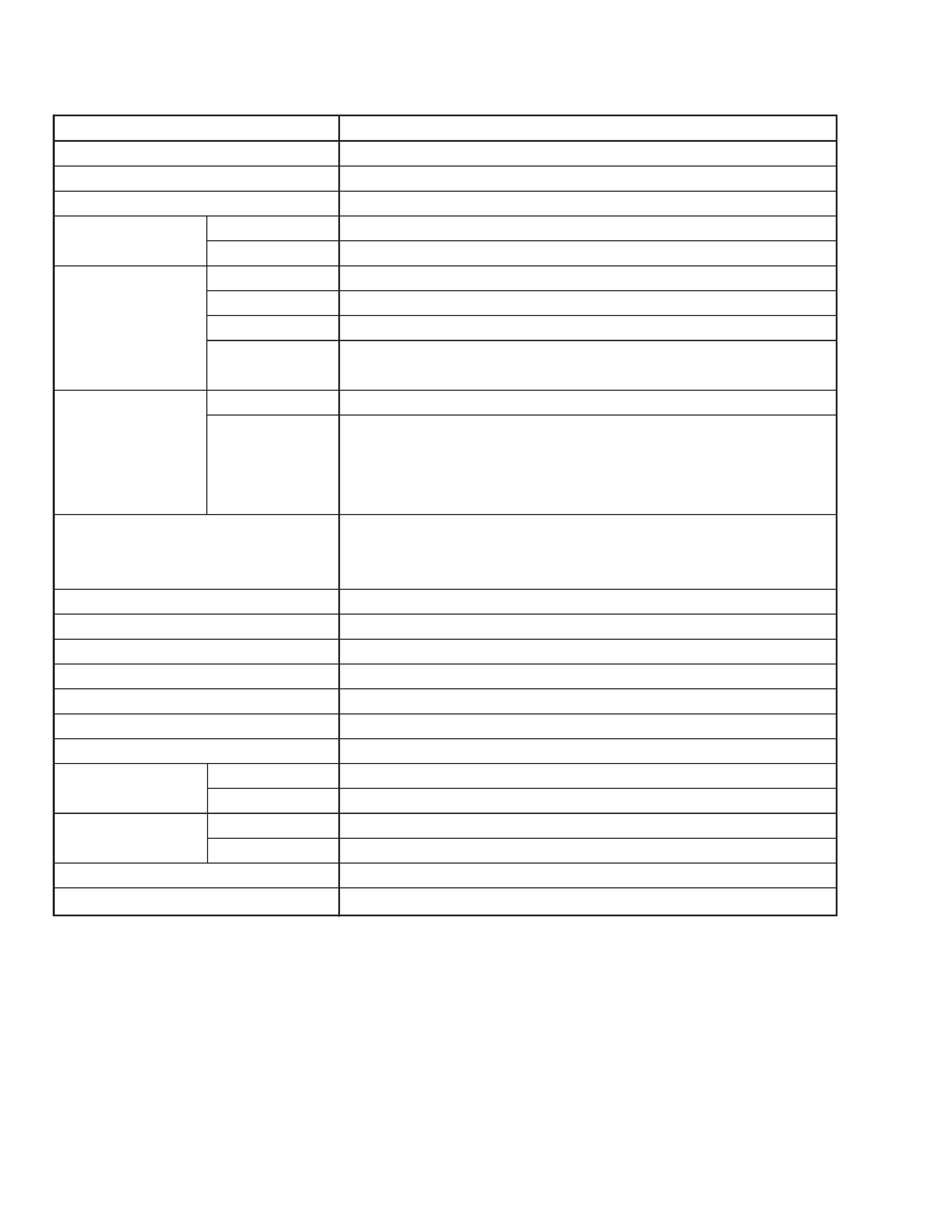
SPECIFICATIONS
Item
Content
Dimensions (W
× H × D)
502mm
× 451mm × 480.5mm
Mass
19.5kg
TV RF System
B / G, I, D / K, K1
Colour System
TV Mode
PAL / SECAM
VIDEO Mode
PAL / SECAM / NTSC3.58 / NTSC4.43
Receiving Frequency VHF (VL)
46.25MHz ~ 168.25MHz
VHF (VH)
175.25MHz ~ 463.25MHz
UHF
471.25MHz ~ 863.25MHz
CATV
q Cable TVs of Mid (X-Z, S1-S10)
Super (S11-S20) & Hyper (S21-S41) bands receivable
Intermediate
VIF Carrier
38.0MHz
Frequency
31.5MHz (6.5MHz)
SIF Carrier
32.0MHz (6.0MHz)
32.5MHz (5.5MHz)
33.5MHz (4.5MHz)
Colour Sub Carrier Frequency
PAL (4.43MHz)
SECAM (4.40625MHz / 4.25MHz)
NTSC (3.58MHz / 4.43MHz)
Aerial Input Terminal
75
Unbalanced
Power Input
AC110 ~ 240V, 50 / 60Hz
Power Consumption
105W (Max.)/68W (Avg.)
Picture Tube
Visible size : 51cm measured diagonally
High Voltage
26.5kV
± 1.5kV (at zero beam current)
Speaker
5cm
× 9 cm Oval type × 2
Audio Output
5W (Monaural)
Input
Video
1Vp-p, 75
Audio
500mVrms (
-4dBs), High impedance
Output
Video
1Vp-p, 75
Audio
500mVrms (4dBs), Low impedance
Headphone Jack
Stereo mini jack (3.5ø)
Remote Control Unit
RM-C364-1H (Battery size : AA/R06/UM-3
× 2)
Design & specifications are subject to change without notice.
AV-21AT
No. 56013
3
SAFETY PRECAUTIONS
8.
When service is required, observe the original lead dress. Ex-
tra precaution should be given to assure correct lead dress in
the high voltage circuit area. Where a short circuit has occurred,
those components that indicate evidence of overheating should
be replaced. Always use the manufacturer's replacement com-
ponents.
9.
Isolation Check
(Safety for Electrical Shock Hazard)
After re-assembling the product, always perform an isolation
check on the exposed metal parts of the cabinet (antenna ter-
minals, video/audio input and output terminals, Control knobs,
metal cabinet, screw heads, earphone jack, control shafts, etc.)
to be sure the product is safe to operate without danger of elec-
trical shock.
(1) Dielectric Strength Test
The isolation between the AC primary circuit and all metal parts
exposed to the user, particularly any exposed metal part hav-
ing a return path to the chassis should withstand a voltage of
3000V AC (r.m.s.) for a period of one second.
(. . . . Withstand a voltage of 1100V AC (r.m.s.) to an appliance
rated up to 120V, and 3000V AC (r.m.s.) to an appliance rated
200V or more, for a period of one second.)
This method of test requires a test equipment not generally
found in the service trade.
(2) Leakage Current Check
Plug the AC line cord directly into the AC outlet (do not use a
line isolation transformer during this check.). Using a "Leakage
Current Tester", measure the leakage current from each ex-
posed metal part of the cabinet, particularly any exposed metal
part having a return path to the chassis, to a known good earth
ground (water pipe, etc.). Any leakage current must not exceed
0.5mA AC (r.m.s.).
However, in tropical area, this must not exceed 0.2mA AC
(r.m.s.).
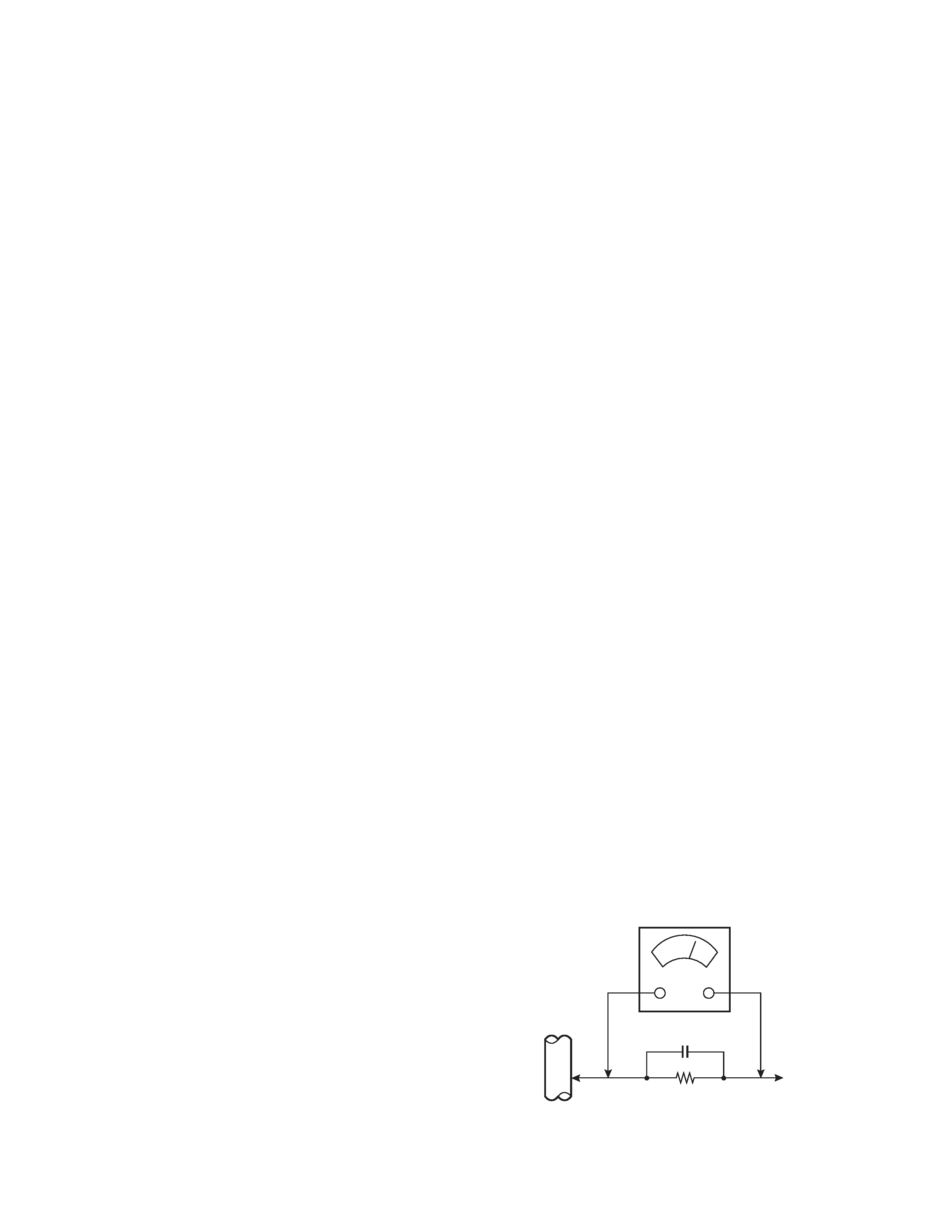
q Alternate Check Method
Plug the AC line cord directly into the AC outlet (do not use a
line isolation transformer during this check.). Use an AC volt-
meter having 1000 ohms per volt or more sensitivity in the fol-
lowing manner. Connect a 1500
10W resistor paralleled by a
0.15
µF AC-type capacitor between an exposed metal part and
a known good earth ground (water pipe, etc.). Measure the AC
voltage across the resistor with the AC voltmeter. Move the
resistor connection to each exposed metal part, particularly any
exposed metal part having a return path to the chassis, and
measure the AC voltage across the resistor. Now, reverse the
plug in the AC outlet and repeat each measurement. Any volt-
age measured must not exceed 0.75V AC (r.m.s.). This corre-
sponds to 0.5mA AC (r.m.s.).
However, in tropical area, this must not exceed 0.3V AC (r.m.s.).
This corresponds to 0.2mA AC (r.m.s.).
1.
The design of this product contains special hardware, many
circuits and components specially for safety purposes. For con-
tinued protection, no changes should be made to the original
design unless authorized in writing by the manufacturer. Re-
placement parts must be identical to those used in the original
circuits. Service should be performed by qualified personnel
only.
2.
Alterations of the design or circuitry of the products should not
be made. Any design alterations or additions will void the
manufacturer's warranty and will further relieve the manufac-
turer of responsibility for personal injury or property damage
resulting therefrom.
3.
Many electrical and mechanical parts in the products have spe-
cial safety-related characteristics. These characteristics are of-
ten not evident from visual inspection nor can the protection
afforded by them necessarily be obtained by using replace-
ment components rated for higher voltage, wattage, etc. Re-
placement parts which have these special safety characteris-
tics are identified in the parts list of Service manual. Electrical
components having such features are identified by shad-
ing on the schematics and by (!) on the parts list in Ser-
vice manual. The use of a substitute replacement which does
not have the same safety characteristics as the recommended
replacement part shown in the parts list of Service manual may
cause shock, fire, or other hazards.
4.
Don't short between the LIVE side ground and ISOLATED
(NEUTRAL) side ground or EARTH side ground when re-
pairing.
Some model's power circuit is partly different in the GND. The
difference of the GND is shown by the LIVE : (#) side GND,
the ISOLATED (NEUTRAL) : (") side GND and EARTH : ($)
side GND. Don't short between the LIVE side GND and ISO-
LATED (NEUTRAL) side GND or EARTH side GND and never
measure with a measuring apparatus (oscilloscope etc.) the
LIVE side GND and ISOLATED (NEUTRAL) side GND or
EARTH side GND at the same time.
If above note will not be kept, a fuse or any parts will be bro-
ken.
5.
If any repair has been made to the chassis, it is recommended
that the B1 setting should be checked or adjusted (See AD-
JUSTMENT OF B1 POWER SUPPLY).
6.
The high voltage applied to the picture tube must conform with
that specified in Service manual. Excessive high voltage can
cause an increase in X-Ray emission, arcing and possible com-
ponent damage, therefore operation under excessive high volt-
age conditions should be kept to a minimum, or should be pre-
vented. If severe arcing occurs, remove the AC power immedi-
ately and determine the cause by visual inspection (incorrect
installation, cracked or melted high voltage harness, poor sol-
dering, etc.). To maintain the proper minimum level of soft X-
Ray emission, components in the high voltage circuitry includ-
ing the picture tube must be the exact replacements or alterna-
tives approved by the manufacturer of the complete product.
7.
Do not check high voltage by drawing an arc. Use a high volt-
age meter or a high voltage probe with a VTVM. Discharge the
picture tube before attempting meter connection, by connect-
ing a clip lead to the ground frame and connecting the other
end of the lead through a 10k
2W resistor to the anode but-
ton.
AC VOLTMETER
(HAVING 1000
/V,
OR MORE SENSITIVITY)
PLACE THIS PROBE
ON EACH EXPOSED
METAL PART
1500
10W
0.15
µF AC-TYPE
GOOD EARTH GROUND