SERVICE MANUAL
AV-20FD23
TV/DVD COMBO
No. 52014
May 2002
COPYRIGHT © 2002 VICTOR COMPANY OF JAPAN, LTD.
AV-20FD23
POWER
RM-C394G
123
DISPLAY
789
456
SLEEP TIMER
0TV RETURN
LIGHT
TV CATV
PAUSE/STILL
OPEN/CLOSE
TV / DVD
RETURN
AUDIO
REPEATA-B
CANCEL
SLOW
ZOOM
TITLE
AUDIO
ANGLE
SUBTITLE
INPUT
C.C.
DVD SETUP
SELECT
/ENTER
TV MENU
MUTING
DVD
CONTROL
PLAY MODE
PREV NEXT
TV/DVD DVD MENU
F.SEARCH
PLAY
B.SEARCH
STOP
+
CH
VOL
VOL
+
CH
CONTENTS
a SPECIFICATIONS ....................................................................................................................................2
¤ OPERATING INSTRUCTIONS (APPENDED)
a SAFETY PRECAUTIONS ........................................................................................................................3
a SPECIFIC SERVICE INSTRUCTIONS ....................................................................................................8
a SERVICE ADJUSTMENTS ....................................................................................................................16
a GUIDE FOR REPAIRING .......................................................................................................................22
¤ STANDARD CIRCUIT DIAGRAM ........................................................................................................ 2-1
a PARTS LIST ...........................................................................................................................................33

2
No. 52014
AV-20FD23
SPECIFICATIONS
TELEVISION
Picture Tube:
20" (measured diagonally)
Tuner Type:
Quartz PLL Frequency Synthesized
Receiving Channels:
VHF
2-13
UHF
14-69
CATV
14-36 (A)-(W)
37-59 (AA)-(WW)
60-85 (AAA)-(ZZZ)
86-94 (86)-(94)
95-99 (A-5)-(A-1)
100-125 (100)-(125)
01 (5A)
Antenna Input:
VHF/UHF In 75 ohms coaxial
Speaker:
3", 8 ohms x 2
Audio Output Power:
2.5 + 2.5 W
DVD/CD player
Signal system:
NTSC
Applicable disc:
1. DVD (12cm, 8cm)
2. CD (12cm, 8cm)
Audio characteristics:
DVD: 4Hz - 22KHz
Frequency response:
CD: 4Hz - 20KHz
S/N Ratio:
90dB
Harmonic distortion:
0.06%
Wow and flutter:
Below Measurable Level
Dynamic range:
96dB
Input/Output:
Inputs
: Video : (RCA) 1 Vp-p/75ohm
Audio : (RCA) 8 dB/50Kohm
Outputs : Video : (RCA) 1 Vp-p/75ohm
Audio : (RCA) 8 dB/1Kohm
GENERAL
Power Source:
AC 120V 60Hz
Power Consumption:
110 Watts
Dimensions:
W 22-5/8" x D 19-1/8" x H 20-3/8"
Weight:
56.1 Ibs/25.5 kg
Inputs:
Video: In (RCA) 1Vp-p 75 ohm
Audio: In (RCA) -8 dB/50K ohm
Headphone Jack:
3.5mm mini-jack
Storage Temperature
-20 °C ~ 60 °C
Operating Temperature
5 °C ~ 40 °C
Accessories:
Remote Control X 1
Batteries (AA) X 2
Design & specification are subject to change without notice.
AV-20FD23
No. 52014
3
SAFETY PRECAUTIONS
SERVICING NOTICES ON CHECKING
6. AVOID AN X-RAY
1. KEEP THE NOTICES
As for the places which need special attentions,
they are indicated with the labels or seals on the
cabinet, chassis and parts. Make sure to keep the
indications and notices in the operation manual.
3. USE THE DESIGNATED PARTS
5. TAKE CARE TO DEAL WITH THE
CATHODE-RAY TUBE
In the condition that an explosion-proof cathode-
ray tube is set in this equipment, safety is
secured against implosion. However, when
removing it or serving from backward, it is
dangerous to give a shock. Take enough care to
deal with it.
Safety is secured against an X-ray by consider-
ing about the cathode-ray tube and the high
voltage peripheral circuit, etc.
Therefore, when repairing the high voltage pe-
ripheral circuit, use the designated parts and
make sure not modify the circuit.
Repairing except indicates causes rising of high
voltage, and it emits an X-ray from the cathode-
ray tube.
Please include the following informations when you order parts. (Particularly the VERSION LETTER.)
1. MODEL NUMBER and VERSION LETTER
The MODEL NUMBER can be found on the back of each product and the VERSION LETTER can be
found at the end of the SERIAL NUMBER.
2. PART NO. and DESCRIPTION
You can find it in your SERVICE MANUAL.
HOW TO ORDER PARTS
PERFORM A SAFETY CHECK AFTER
SERVICING
7.
Confirm that the screws, parts and wiring which
were removed in order to service are put in the
original positions, or whether there are the
portions which are deteriorated around the
serviced places serviced or not. Check the
insulation between the antenna terminal or
external metal and the AC cord plug blades.
And be sure the safety of that.
(INSULATION CHECK PROCEDURE)
1.
2.
3.
4.
Unplug the plug from the AC outlet.
Remove the antenna terminal on TV and turn
on the TV.
Insulation resistance between the cord plug
terminals and the eternal exposure metal
[Note 2] should be more than 1M ohm by
using the 500V insulation resistance meter
[Note 1].
If the insulation resistance is less than 1M
ohm, the inspection repair should be
required.
[Note 1]
If you have not the 500V insulation
resistance meter, use a Tester.
[Note 2]
External exposure metal: Antenna terminal
Earphone jack
2. AVOID AN ELECTRIC SHOCK
There is a high voltage part inside. Avoid an
electric shock while the electric current is
flowing.
The parts in this equipment have the specific
characters of incombustibility and withstand
voltage for safety. Therefore, the part which is
replaced should be used the part which has
the same character.
Especially as to the important parts for safety
which is indicated in the circuit diagram or the
table of parts as a
mark, the designated
parts must be used.
4. PUT PARTS AND WIRES IN THE
ORIGINAL POSITION AFTER
ASSEMBLING OR WIRING
There are parts which use the insulation
material such as a tube or tape for safety, or
which are assembled in the condition that
these do not contact with the printed board.
The inside wiring is designed not to get closer
to the pyrogenic parts and high voltage parts.
Therefore, put these parts in the original
positions.
4
No. 52014
AV-20FD23
CAUTION
THIS DIGITAL VIDEO PLAYER EMPLOYS A LASER SYSTEM.
TO ENSURE PROPER USE OF THIS PRODUCT, PLEASE READ THIS SERVICE MANUAL CARE-
FULLY AND RETAIN FOR FUTURE REFERENCE. SHOULD THE UNIT REQUIRE MAINTENANCE,
CONTACT AN AUTHORIZED SERVICE LOCATION-SEE SERVICE PROCEDURE.
USE OF CONTROLS, ADJUSTMENTS OR THE PERFORMANCE OF PROCEDURES OTHER THAN
THOSE SPECIFIED HEREIN MAY RESULT IN HAZARDOUS RADIATION EXPOSURE.
TO PREVENT DIRECT EXPOSURE TO LASER BEAM, DO NOT TRY TO OPEN THE ENCLOSURE.
VISIBLE LASER RADIATION MAY BE PRESENT WHEN THE ENCLOSURE IS OPENED. DO NOT
STARE INTO BEAM.
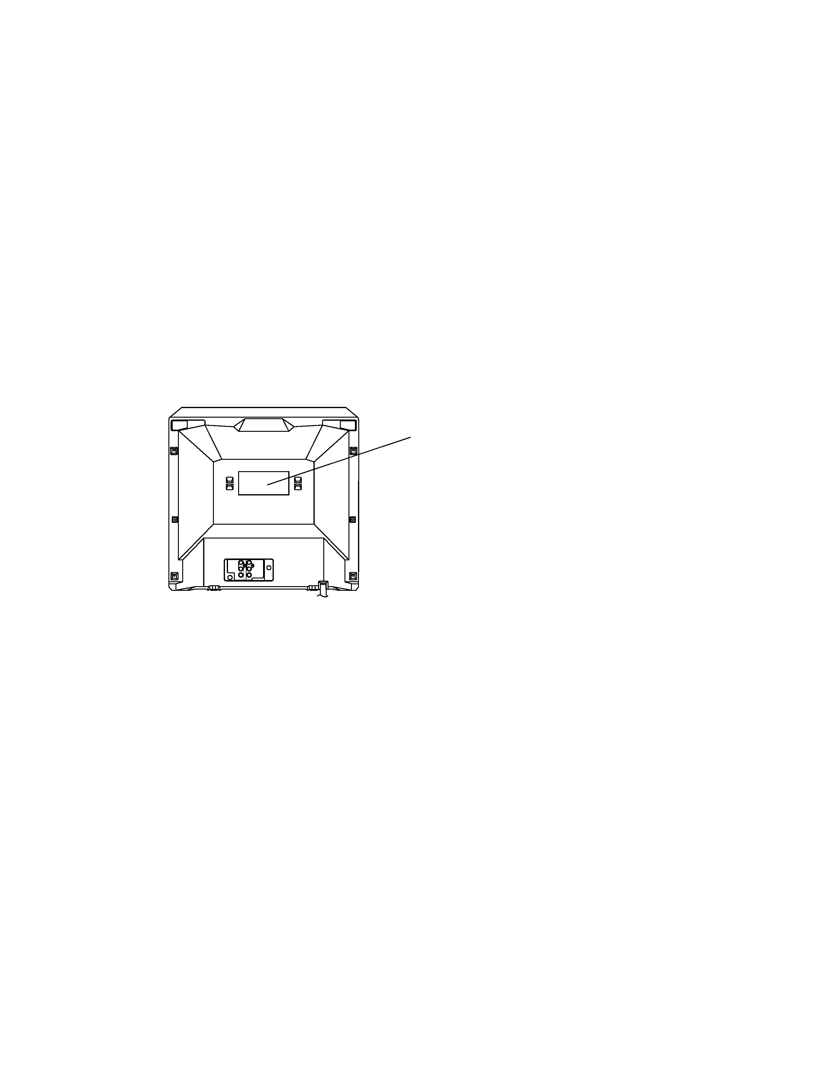
Location of the required Marking
The rating sheet and the safety caution are on the rear of the unit.
CERTIFICATION: COMPLIES WITH FDA
RADIATION PERFORMANCE STANDARDS,
21 CFR SUBCHAPTER J.

AV-20FD23
No. 52014
5
IMPORTANT SERVICE SAFETY INFORMATION
Operating the receiver outside of its cabinet or with its
back removed involves a shock hazard. Work on these
models should only be performed by those who are
thoroughly familiar with precautions necessary when
working on high voltage equipment.
Exercise care when servicing this chassis with power
applied. Many B plus and high voltage RF terminals are
exposed which, if carelessly contacted, can cause
serious shock or result in damage to the chassis.
Maintain interconnecting ground lead connections
between chassis, escutcheon, picture tube dag and
tuner cluster when operating the chassis.
These receivers have a "polarized" AC line cord. The
AC plug is designed to fit into standard AC outlets in one
direction only. The wide blade connects to the "ground
side" and the narrow blade connects to the "hot side" of
the AC line. This assures that the TV receiver is properly
grounded to the house wiring. If an extension cord must
be used, make sure it is of the "polarized" type.
Since the chassis of this receiver is connected to one
side of the AC supply during operation, service should
not be attempted by anyone not familiar with the
precautions necessary when working on these types of
equipment.
When it is necessary to make measurements or tests
with AC power applied to the receiver chassis, an
Isolation Transformer must be used as a safety
precaution and to prevent possible damage to
transistors. The Isolation Transformer should be
connected between the TV line cord plug and the AC
power outlet.
Certain HV failures can increase X-ray radiation.
Receivers should not be operated with HV levels
exceeding the specified rating for their chassis type. The
maximum operating HV specified for the chassis used in
these receivers is 32kV
±1.0kV at zero beam current with
a line voltage of 120V AC. Higher voltage may also
increase the possibility of failure in the HV supply.
It is important to maintain specified values of all
components in the horizontal and high voltage circuits
and anywhere else in the receiver that could cause a
rise in high voltage, or operating supply voltages. No
changes should be made to the original design of the
receiver.
Components shown in the shaded areas on the
schematic diagram and/or identified by
in the
replacement parts list should be replaced only with exact
factory recommended replacement parts. The use of
unauthorized substitute parts may create shock, fire, X-
ray radiation, or other hazards.
To determine the presence of high voltage, use an
accurate high impedance HV meter connected between
the second anode lead and the CRT dag grounding
device. When servicing the High Voltage System,
remove static charges from it by connecting a 10k ohm
resistor in series with an insulated wire (such as a test
probe) between the picture tube dag and 2nd anode
lead (have AC line cord disconnected from AC supply).
The picture tube used in this receiver employs integral
implosion protection. Replace with a tube of the same
type number for continued safety. Do not lift picture tube
by the neck. Handle the picture tube only when wearing
shatterproof goggles and after discharging the high
voltage completely. Keep others without shatterproof
goggles away.
When removing springs or spring mounted parts from
the tuner, tuner cluster or chassis, shatterproof goggles
must be worn. Keep others without shatterproof goggles
away.
Before returning the receiver to the user, perform the
following safety checks:
1.
2.
3.
Plug the AC line cord directly into a 120V AC receptacle.
(Do not use an Isolation Transformer during these
checks.) All checks must be repeated with the AC line
cord plug connection reversed. (If necessary, a
nonpolarized adapter plug must be used only for the
purpose of completing these checks.)
If available, measure current using an accurate leakage
current tester. Any reading of 0.35mA or more is
excessive and indicates a potential shock hazard which
must be corrected before returning the receiver to the
owner.
If a reliable leakage current tester is not available, this
alternate method of measurement should be used.
Using two clip leads, connect a 1500 ohm, 10 watt
resistor paralleled by a 0.15
µF capacitor in series with a
known earth ground, such as a water pipe or conduit
and the metal part to be checked. Use a VTVM or VOM
with 1000 ohms per volt, or higher, sensitivity to
measure this AC voltage drop across the resistor. Any
reading of 0.35 volt RMS or more is excessive and
indicates a potential shock hazard which must be
corrected before returning the receiver to the owner.
Inspect all lead dress to make certain that leads are
not pinched or that hardware is not lodged between
the chassis and other metal parts in the receiver.
Replace all protective devices such as nonmetallic
control knobs, insulating fishpapers, cabinet backs,
adjustment and compartment covers or shields,
isolation resistor-capacitor networks, mechanical
insulators, etc.
To be sure that no shock hazard exists, a check for
the presence of leakage current should be made at
each exposed metal part having a return path to the
chassis (antenna, cabinet metal, screw heads, knobs
and/or shafts, escutcheon, etc.) in the following
manner.
TO KNOWN
EARTH GROUND
AC SCALE
VT VM
1.5K OHMS
10W
15
µF
TEST PROBE
TO EXPOSED
METAL PARTS