SERVICE MANUAL
VIDEO CASSETTE RECORDER
This video deck is VHS type video
recorder. For proper operation, only
the VHS type cassette must be
used.
SM5204
VTFX240EUK
VTMX210EUK
June
2002
SPECIFICATIONS AND PARTS ARE SUBJECT TO CHANGE FOR IMPROVEMENT
Digital Media Division

CONTENTS
SPECIFICATIONS. . . . . . . . . . . . . . . . . . . . . . . . . . . . . 1-1-1
FUNCTION INDICATOR SYMBOLS . . . . . . . . . . . . . . 1-2-1
IMPORTANT SAFETY PRECAUTIONS . . . . . . . . . . . . 1-3-1
Product Safety Notice . . . . . . . . . . . . . . . . . . . . . . . . . 1-3-1
Precautions during Servicing. . . . . . . . . . . . . . . . . . . . 1-3-1
Safety Check after Servicing . . . . . . . . . . . . . . . . . . . . 1-3-2
STANDARD NOTES FOR SERVICING . . . . . . . . . . . . 1-4-1
Circuit Board Indications . . . . . . . . . . . . . . . . . . . . . . . 1-4-1
Instructions for Connectors . . . . . . . . . . . . . . . . . . . . . 1-4-1
How to Remove/Install Flat Pack-IC . . . . . . . . . . . . . . 1-4-1
Instructions for Handling
Semi-conductors . . . . . . . . . . . . . . . . . . . . . . . . . . . 1-4-3
PREPARATION FOR SERVICING . . . . . . . . . . . . . . . . 1-5-1
How to Enter the Service Mode. . . . . . . . . . . . . . . . . . 1-5-1
TROUBLESHOOTING . . . . . . . . . . . . . . . . . . . . . . . . . 1-6-1
ORERATING CONTROLS AND FUNCTIONS . . . . . . . 1-7-1
CABINET DISASSEMBLY INSTRUCTIONS . . . . . . . . 2-1-1
1. Disassembly Flowchart . . . . . . . . . . . . . . . . . . . . . . 2-1-1
2. Disassembly Method . . . . . . . . . . . . . . . . . . . . . . . . 2-1-1
DISASSEMBLY/ASSEMBLY PROCEDURES OF
DECK MECHANISM . . . . . . . . . . . . . . . . . . . . . . . . . . 2-2-1
ALIGNMENT PROCEDURES OF MECHANISM . . . . . 2-3-1
ELECTRICAL ADJUSTMENT INSTRUCTIONS . . . . . 2-4-1
Test Equipment Required . . . . . . . . . . . . . . . . . . . . . . 2-4-1
Head Switching Position Adjustment. . . . . . . . . . . . . . 2-4-1
FIXTURE AND TAPE FOR ADJUSTMENT . . . . . . . . . 2-5-1
How to Use The Fixtures . . . . . . . . . . . . . . . . . . . . . . . 2-5-1
MECHANICAL ALIGNMENT PROCEDURES . . . . . . . 2-6-1
Service Information . . . . . . . . . . . . . . . . . . . . . . . . . . . 2-6-1
1. Tape Interchangeability Alignment. . . . . . . . . . . . . . 2-6-2
1-A.Preliminary/Final Checking and
Alignment of Tape Path . . . . . . . . . . . . . . . . . . . 2-6-3
1-B.X Value Alignment . . . . . . . . . . . . . . . . . . . . . . . . 2-6-3
1-C.Checking/Adjustment of Envelope Waveform . . . 2-6-4
1-D.Azimuth Alignment of
Audio/Control/Erase Head . . . . . . . . . . . . . . . . . 2-6-4
STANDARD MAINTENANCE . . . . . . . . . . . . . . . . . . . . 2-7-1
Service Schedule Components . . . . . . . . . . . . . . . . . . 2-7-1
Cleaning . . . . . . . . . . . . . . . . . . . . . . . . . . . . . . . . . . . 2-7-2
EXPLODED VIEWS . . . . . . . . . . . . . . . . . . . . . . . . . . . 3-1-1
Front Panel . . . . . . . . . . . . . . . . . . . . . . . . . . . . . . . . . 3-1-1
Cabinet . . . . . . . . . . . . . . . . . . . . . . . . . . . . . . . . . . . . 3-1-2
Deck Mechanism View 1 . . . . . . . . . . . . . . . . . . . . . . . 3-1-3
Deck Mechanism View 2 . . . . . . . . . . . . . . . . . . . . . . . 3-1-4
Deck Mechanism View 3 . . . . . . . . . . . . . . . . . . . . . . . 3-1-5
REPLACEMENT PARTS LIST . . . . . . . . . . . . . . . . . . . 3-2-1
Mechanical Parts List . . . . . . . . . . . . . . . . . . . . . . . . . 3-2-1
Electrical Parts List . . . . . . . . . . . . . . . . . . . . . . . . . . . 3-2-3
SCHEMATIC DIAGRAMS/CBA'S AND
TEST POINTS. . . . . . . . . . . . . . . . . . . . . . . . . . . . . . . 4-1-1
Wiring Diagrams . . . . . . . . . . . . . . . . . . . . . . . . . . . . . 4-1-3
Main 1/5 Schematic Diagram . . . . . . . . . . . . . . . . . . . 4-1-4
Main 2/5 Schematic Diagram . . . . . . . . . . . . . . . . . . . 4-1-5
Main 3/5 Schematic Diagram . . . . . . . . . . . . . . . . . . . 4-1-6
Main 4/5 Schematic Diagram . . . . . . . . . . . . . . . . . . . 4-1-7
Main 5/5 Schematic Diagram ( VT-FX240EUK ) . . . . . 4-1-8
Function Schematic Diagram . . . . . . . . . . . . . . . . . . . 4-1-9
AFV Schematic Diagram ( VT-FX240EUK ) . . . . . . . 4-1-10
Jack Schematic Diagram. . . . . . . . . . . . . . . . . . . . . . 4-1-11
Main CBA Top View . . . . . . . . . . . . . . . . . . . . . . . . . 4-1-12
Main CBA Bottom View . . . . . . . . . . . . . . . . . . . . . . . 4-1-13
Function/Power SW CBA Top/Bottom View . . . . . . . 4-1-14
AFV CBA Top/Bottom View. . . . . . . . . . . . . . . . . . . . 4-1-15
Jack CBA Top/Bottom View . . . . . . . . . . . . . . . . . . . 4-1-16
BLOCK DIAGRAMS . . . . . . . . . . . . . . . . . . . . . . . . . . . 4-2-1
Servo/System Control Block Diagram . . . . . . . . . . . . 4-2-1
Video Block Diagram(VT-MX210EUK) . . . . . . . . . . . . 4-2-2
Video Block Diagram(VT-FX240EUK). . . . . . . . . . . . . 4-2-3
Audio Block Diagram(VT-MX210EUK) . . . . . . . . . . . . 4-2-4
Audio Block Diagram(VT-FX240EUK). . . . . . . . . . . . . 4-2-5
Hi-Fi Audio Block Diagram(VT-FX240EUK) . . . . . . . . 4-2-6
Power Supply Block Diagram . . . . . . . . . . . . . . . . . . . 4-2-7
SYSTEM CONTROL TIMING CHARTS . . . . . . . . . . . . 4-3-1
IC PIN FUNCTION DESCRIPTIONS . . . . . . . . . . . . . . 4-4-1
LEAD IDENTIFICATIONS. . . . . . . . . . . . . . . . . . . . . . . 4-5-1
CHAPTER 1 GENERAL INFORMATION
CHAPTER 2 DISASSEMBLY AND ADJUSTMENT
CHAPTER 3 EXPLODED VIEWS AND PARTS LIST
CHAPTER 4
SCHEMATIC AND BLOCK DIAGRAMS/
CBA'S
1-1-1
Video output level :
1Vp-p
Video output impedance :
75
unbalanced
Audio output level :
-6dBv
Video input level :
0.5 to 2.0Vp-p
Audio input level :
-10dBv
Video S/N ratio
(STANDARD):
45dB
Audio S/N ratio
(STANDARD):
41dB
Power requirement :
220-240V to 50Hz
Power consumption :
20 Watts (Stand by: 3.3 watts)
Dimensions :
W 360mm
H
92mm
D
226mm
Weight :
2.6 kg. (approx.)
General Specifications
Electrical Specifications
Other Specifications
Television system:
PAL I
TV standard
Video heads
Rotary two-head
Helical scan system
Tape width :
12.65mm
Tape speed
SP :
23.39mm/s
LP :
11.70mm/s
Tuner channel
IRA to IRJ
E21 to E69
CATV
RF converter :
Built-in UHF converter
Converter output :
UHF Channel 22 to 69
(adjustable)
Timer indication :
24-hour system
Operating temperature :
5 C to 40 C
Terminals
AERIAL :
Coaxial type, male
RF OUT :
Coaxial type, female
AUDIO/VIDEO :
21 pin scart socket x 2
Video output level :
1Vp-p
Video output impedance :
75
unbalanced
Audio output level :
-6dBv
Video input level :
0.5 to 2.0Vp-p
Audio input level :
-10dBv
Video S/N ratio
(STANDARD):
45dB
Audio S/N ratio
(STANDARD):
41dB
Power requirement :
220-240V to 50Hz
Power consumption :
20 Watts (Stand by:3.3 watts)
Dimensions :
W 360mm
H
92mm
D
226mm
Weight :
2.6 kg. (approx.)
General Specifications
Electrical Specifications
Other Specifications
Designs and specifications are subject to change with-
out notice.
Television system:
PAL I
TV standard
Video heads
Six comprising of Four-video
and Two-audio heads
Helical scan system
Tape width :
12.65mm
Tape speed
SP :
23.39mm/s
LP :
11.70mm/s
Tuner channel
IRA to IRJ
E21 to E69
CATV
RF converter :
Built-in UHF converter
Converter output :
UHF Channel 22 to 69
(adjustable)
Timer indication :
24-hour system
Operating temperature :
5 C to 40 C
Terminals
AERIAL :
Coaxial type, male
RF OUT :
Coaxial type, female
AUDIO/VIDEO :
21 pin scart socket x 2
AUDIO output:
RCA connector x 2
SPECIFICATIONS
VT-FX240EUK
VT-MX210EUK
CHAPTER 1
GENERAL INFORMATION
1-2-1
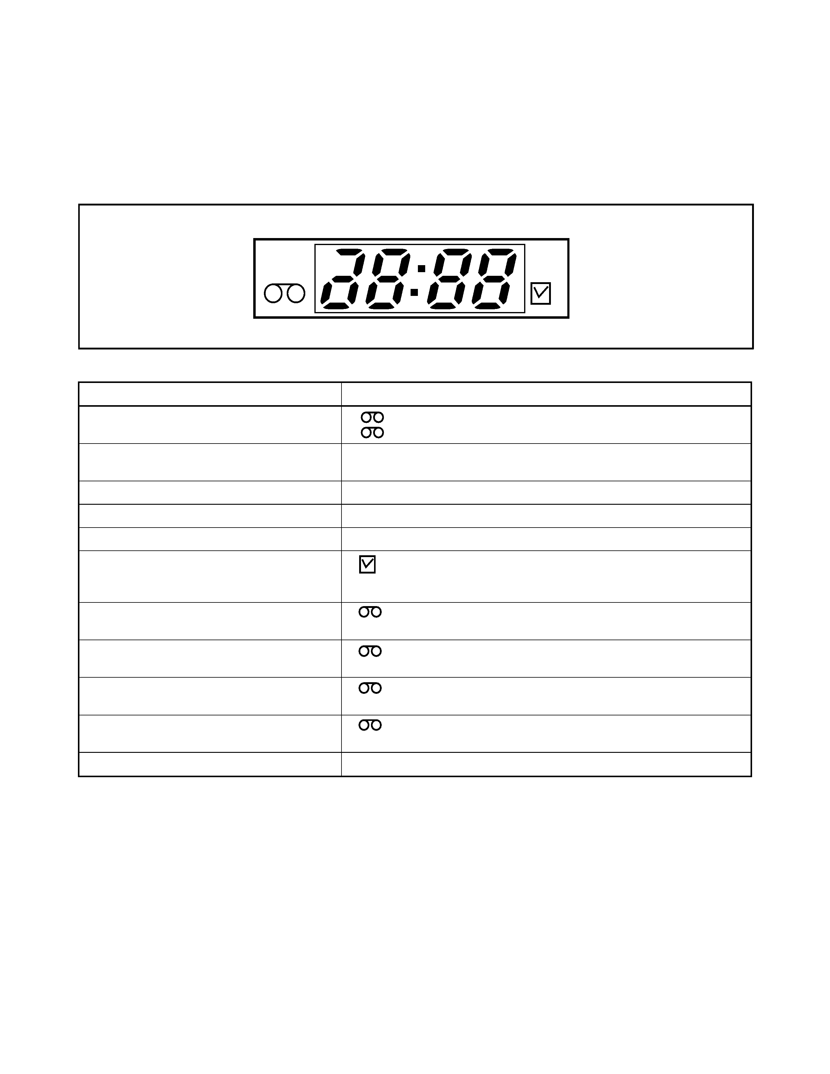
FUNCTION INDICATOR SYMBOLS
Note:
The following symbols will appear on the indicator panel to indicate the current mode or operation of the VCR.
On-screen modes will also be momentarily displayed on the tv screen when you press the operation buttons.
Display panel
PWR.
REC
" H "= LED Light on, " L "= LED Light off
LED MODE
INDICATOR ACTIVE
CASSETTE "IN"
CASSETTE "OUT"
"
"
"
"
ON
OFF
CLOCK
" 88:88 "
" PM "
ON
ON/OFF
POWER ON
" PWR. "
ON
REC
" REC "
ON
REC PAUSE
" REC "
Blinks at 0.8Hz interval
T-REC, OTR
"
"
ON
(T-REC OFF, T-REC incomplete
Blinks at 0.8Hz interval)
When reel and capstan mechanism is not
functioning correctly
"
"
"
1 "
Blinks at 0.8Hz interval
When tape loading mechanism is not func-
tioning correctly
"
"
"
2 "
Blinks at 0.8Hz interval
When cassette loading mechanism is not
functioning correctly
"
"
"
3 "
Blinks at 0.8Hz interval
When the drum is not working properly
"
"
"
4 "
Blinks at 0.8Hz interval
S-INH condition
All modes
Blinks at 0.8Hz interval

1-3-1
IMPORTANT SAFETY PRECAUTIONS
Product Safety Notice
Some electrical and mechanical parts have special
safety-related characteristics which are often not evi-
dent from visual inspection, nor can the protection
they give necessarily be obtained by replacing them
with components rated for higher voltage, wattage,
etc. Parts that have special safety characteristics are
identified by a ! on schematics and in parts lists. Use
of a substitute replacement that does not have the
same safety characteristics as the recommended
replacement part might create shock, fire, and/or other
hazards. The Product's Safety is under review contin-
uously and new instructions are issued whenever
appropriate. Prior to shipment from the factory, our
products are carefully inspected to confirm with the
recognized product safety and electrical codes of the
countries in which they are to be sold. However, in
order to maintain such compliance, it is equally impor-
tant to implement the following precautions when a set
is being serviced.
Precautions during Servicing
A. Parts identified by the ! symbol are critical for
safety. Replace only with part number specified.
B. In addition to safety, other parts and assemblies
are specified for conformance with regulations
applying to spurious radiation. These must also be
replaced only with specified replacements.
Examples: RF converters, RF cables, noise block-
ing capacitors, and noise blocking filters, etc.
C. Use specified internal wiring. Note especially:
1)Wires covered with PVC tubing
2)Double insulated wires
3)High voltage leads
D. Use specified insulating materials for hazardous
live parts. Note especially:
1)Insulation tape
2)PVC tubing
3)Spacers
4)Insulators for transistors
E. When replacing AC primary side components
(transformers, power cord, etc.), wrap ends of
wires securely about the terminals before solder-
ing.
F. Observe that the wires do not contact heat produc-
ing parts (heatsinks, oxide metal film resistors, fus-
ible resistors, etc.).
G. Check that replaced wires do not contact sharp
edges or pointed parts.
H. When a power cord has been replaced, check that
5 - 6 kg of force in any direction will not loosen it.
I. Also check areas surrounding repaired locations.
J. Use care that foreign objects (screws, solder drop-
lets, etc.) do not remain inside the set.
K. Crimp type wire connector
The power transformer uses crimp type connectors
which connect the power cord and the primary side
of the transformer. When replacing the transformer,
follow these steps carefully and precisely to pre-
vent shock hazards.
Replacement procedure
1)Remove the old connector by cutting the wires at a
point close to the connector.
Important: Do not re-use a connector. (Discard it.)
2)Strip about 15 mm of the insulation from the ends
of the wires. If the wires are stranded, twist the
strands to avoid frayed conductors.
3)Align the lengths of the wires to be connected.
Insert the wires fully into the connector.
4)Use a crimping tool to crimp the metal sleeve at its
center. Be sure to crimp fully to the complete clo-
sure of the tool.
L. When connecting or disconnecting the internal con-
nectors, first, disconnect the AC plug from the AC
outlet.