SPECIFICATIONS AND PARTS ARE SUBJECT TO CHANGE FOR IMPROVEMENT.
Multimedia LCD Projector
May 2004 Digital Media Division
SM0546
PJ-TX100W
(C11H)
SERVICE MANUAL
Be sure to read this manual before servicing. To assure safety from fire, electric shock, injury, harmful
radiation and materials, various measures are provided in this Hitachi Multimedia LCD Projector. Be
sure to read cautionary items described in the manual to maintain safety before servicing.
Caution
1. When replacing the lamp, avoid burns to your fingers as the lamp becomes very hot.
2. Never touch the lamp bulb with a finger or anything else. Never drop it or give it a shock. They may
cause bursting of the bulb.
3. This projector is provided with a high voltage circuit for the lamp. Do not touch the electric parts of
power unit (main), when turn on the projector.
4. Do not touch the exhaust fan during operation.
5. The LCD module assembly is likely to be damaged. If replacing to the LCD LENS/PRISM assembly,
do not hold the FPC of the LCD module assembly.
6. Use the cables which are included with the projector or specified.
Service Warning
Warning
The technical information and parts shown in this
manual are not to be used for: the development,
design, production, storage or use of nuclear, chemical,
biological or missile weapons or other weapons of
mass destruction; or military purposes; or purposes that
endanger global safety and peace. Moreover, do not
sell, give, or export these items, or grant permission for
use to parties with such objectives. Forward all inquiries
to Hitachi Ltd.
1. Features ----------------------------------------------- 2
2. Specifications----------------------------------------- 2
3. Names of each part --------------------------------- 3
4. Adjustment -------------------------------------------- 5
5. Troubleshooting ------------------------------------ 12
6. Service points -------------------------------------- 17
7. Wiring diagram ------------------------------------- 29
8. Disassembly diagram----------------------------- 34
9. Replacement parts list---------------------------- 37
10.RS-232C commands ----------------------------- 38
11. Block diagram -------------------------------------- 47
12.Connector connection diagram ---------------- 48
13.Basic circuit diagram------------------------------ 49
Contents
2
PJ-TX100(C11H)
1. Features
Super focus ED (Extra-low dispersion) lenses are adopted for the highest possible image quality.
720P wide LCD panels realize faithful reproduction of high-definition images.
Motorized iris control is provided for realizing film-like images with blacker black.
1.6x zoom lens and the optical lens shift allow flexible installation and viewing position.
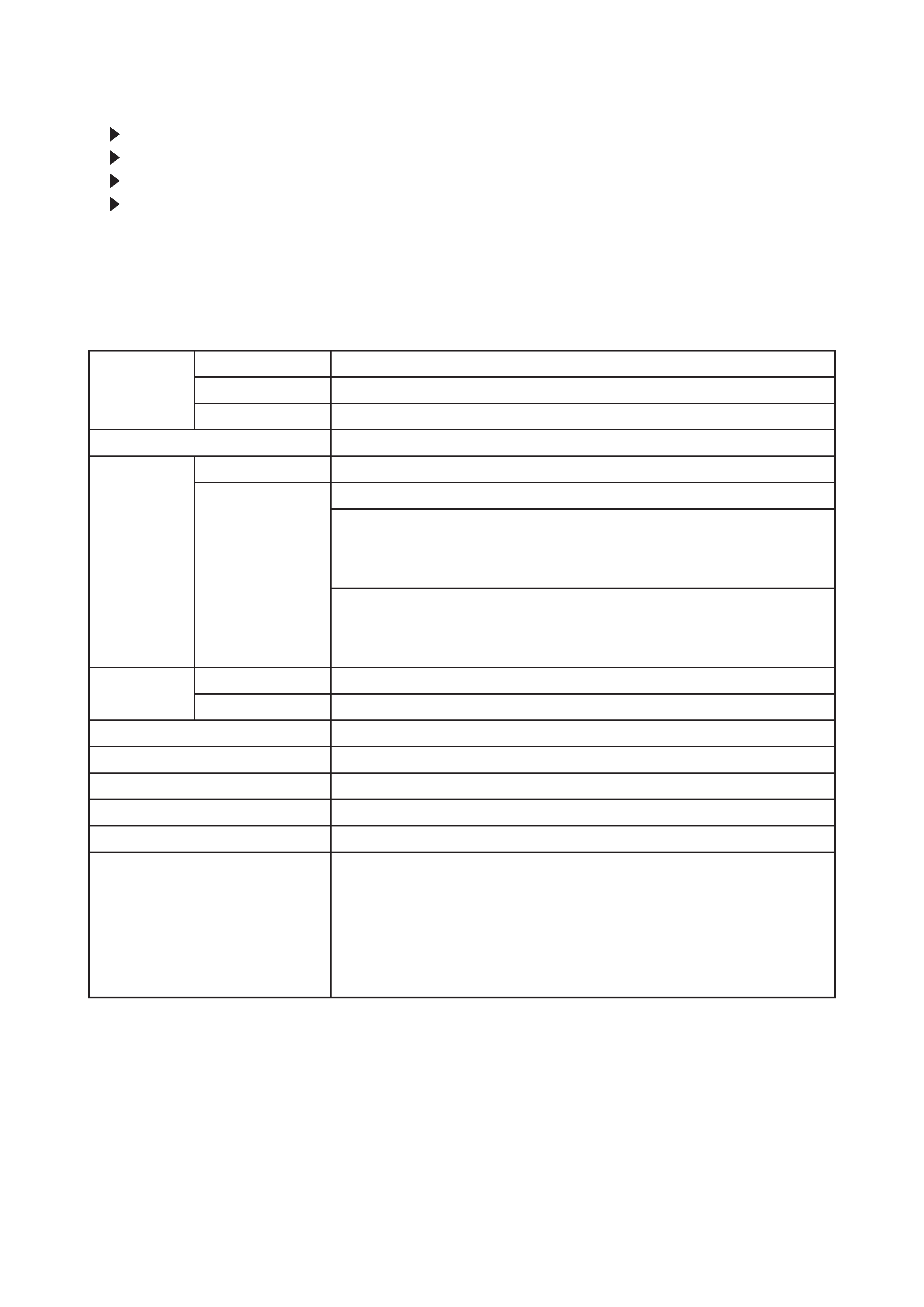
2. Specifications
Liquid
Crystal
Panel
Drive system
TFT active matrix
Panel size
1.8cm (0.7type)
Number of pixels
1280 (H) × 720 (V)
Lamp
150W UHB
Video Input
System
NTSC,PAL(BGDHI),SECAM,PAL-M,PAL-N,NTSC4.43,PAL60
Level
Composite 1.0±0.1Vp-p(75termination)
S-Video Y : 1.0±0.1Vp-p(75termination)
C : 0.286±0.1Vp-p(NTSC burst signal,75termination)
0.3±0.1Vp-p(PAL/SECAM burst signal,75termination)
Component
Y : 1.0±0.1Vp-p(75termination)
CB/PB : 0.7±0.1Vp-p(75termination)
CR/PR : 0.7±0.1Vp-p(75termination)
RGB input /
output
Analog RGB
0.7V p-p (75termination)
Sync.
TTL level
Power supply
AC100~120V / 2.4A , AC220~240V / 1.3A
Power consumption
220W
Dimensions
340(W) × 110(H) × 280(D) mm (No including protruding parts)
Weight
4.4kg(9.7lbs)
Temperature
Operation : 5~35°C
Storage : -20~60°C
Accessories
Power cord
PJ-TX100W x 3 (US, UK, Europe)
PJ-TX100E x 2 (UK, Europe)
PJ-TX100U x 1 (US)
Component cable x 1
Rivet (for Lens cap) x 1
Strap (for Lens cap) x 1
Remote control transmitter x 1
Battery (for Remote control) x 2
User's manual
Quick guide x 1
Safety guide x 1
Operating guide book x 2 or 3
3
PJ-TX100(C11H)
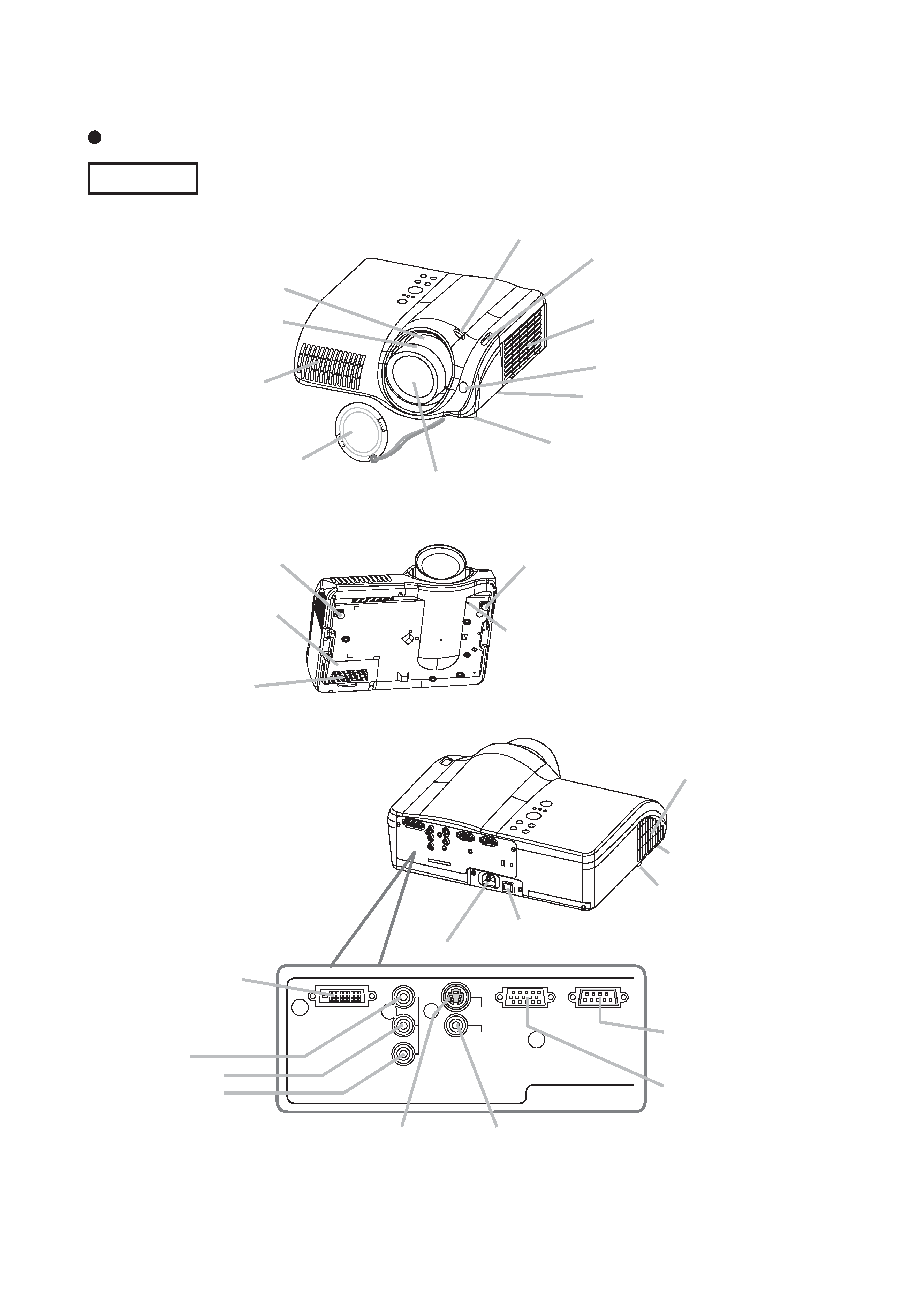
3. Names of each part
Parts names
Projector
Lens
radiates powerful light for projecting an image.
Lens cover
Vertical
lens shift dials
Horizontal
lens shift dials
Filter cover
(An air filter is inside.)
Elevator button
is on the both sides.
Elevator foot
is on the both sides.
Remote sensor
Zoom knob
Focus knob
Exhaust vent
AC inlet
Power switch
Elevator button
DVI-D
Y
CB/PB
CR/PR
COMPONENT VIDEO
S-VIDEO
VIDEO
COMPUTER
CONTROL
DVI-D port
COMPONENT
VIDEO ports
Y
CB/PB
CR/PR
VIDEO port
S-VIDEO port
COMPUTER
port
CONTROL port
Intake vent
Lamp cover
Strap hole
Elevator foot
Elevator foot
(Bottom of projector)
Elevator foot
Exhaust vent
4
PJ-TX100(C11H)
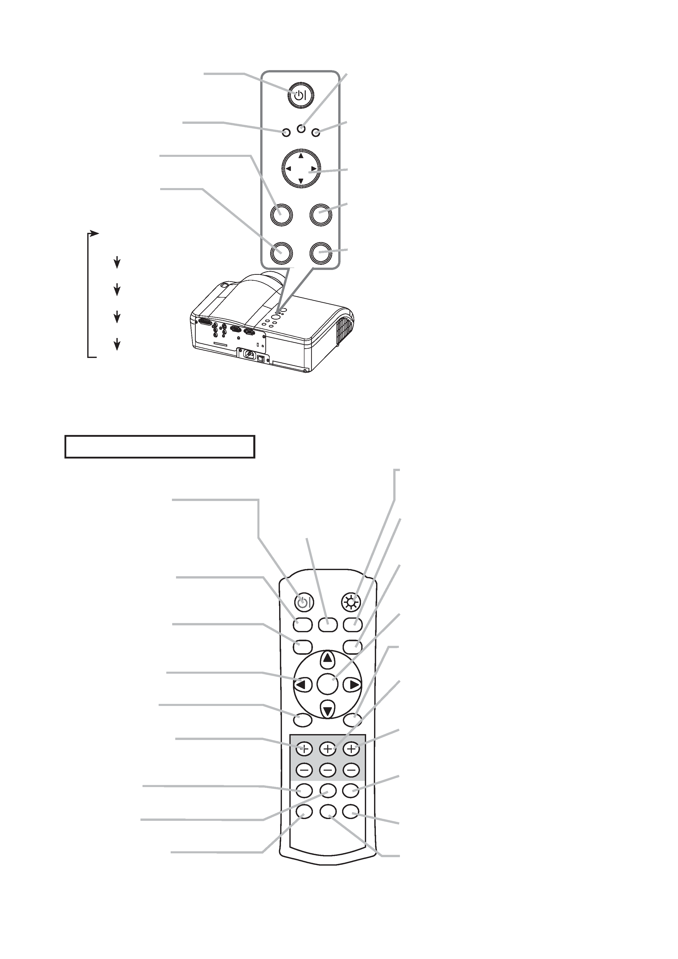
STANDBY/ON button
prepares for turning the power
on/off.
POWER indicator
tells the state of power supply.
MENU button
operates the menu function.
INPUT button
toggles between the
signal ports.
COMPONENT
VIDEO
S-VIDEO
VIDEO
DVI-D
COMPUTER
POWER
MENU
ENTER
LAMP
TEMP
STANDBY/ON
INPUT
RESET
TEMP indicator
lights or blinks when any problem about
internal temperature has happened.
LAMP indicator
light or blinks when any problem about
the lamp has happened.
Cursor buttons
works for adjusting or menu controlling.
ENTER button
proceeds to the next operation at the
menu functions.
RESET button
cancels the adjustment in progress.
* Note that the items whose functions
are performed simultaneously with
operating are nor reset.
POWER button
prepares for turning the
power on/off.
(the same as the
STANDBY/ON button above.)
OPT BLK button
toggles between the
modes for the optical black.
ASPECT button
toggles between the modes for
the aspect ratio.
Cursor buttons
(the same as the above.)
MENU button
(the same as the above.)
BRIGHT buttons
controls the brightness of the
whole screen.
DVI button
selects the DVI-D port input.
PC button
selects the COMPUTER port input.
COMPO button
selects the COMPONENT
VIDEO port input.
POWER
LIGHT
OPT BLK
ASPECT
MENU
BRIGHT CONTRAST COLOR
IRIS
MODE
MEMORY
ENTER
RESET
DVI
PC
AUTO
COMPO
S-VIDEO
VIDEO
LIGHT button
turn on/off the back light for
the remote control buttons.
MEMORY button
toggles between your
adjustments.
IRIS button
toggles between the modes
for the iris.
ENTER button
(the same as the above.)
RESET button
(the same as the above.)
CONTRAST buttons
controls the contrast of the
whole screen.
COLOR buttons
controls the color of the whole
screen.
AUTO button
executes automatic
adjustment.
VIDEO button
selects the VIDEO port input.
S-VIDEO button
selects the S-VIDEO port input.
MODE button
toggles between
the modes for the
picture type.
Remote control transmitter
5
PJ-TX100(C11H)
4. Adjustment
4-1 Before adjusting
4-1-1 Selection of adjustment
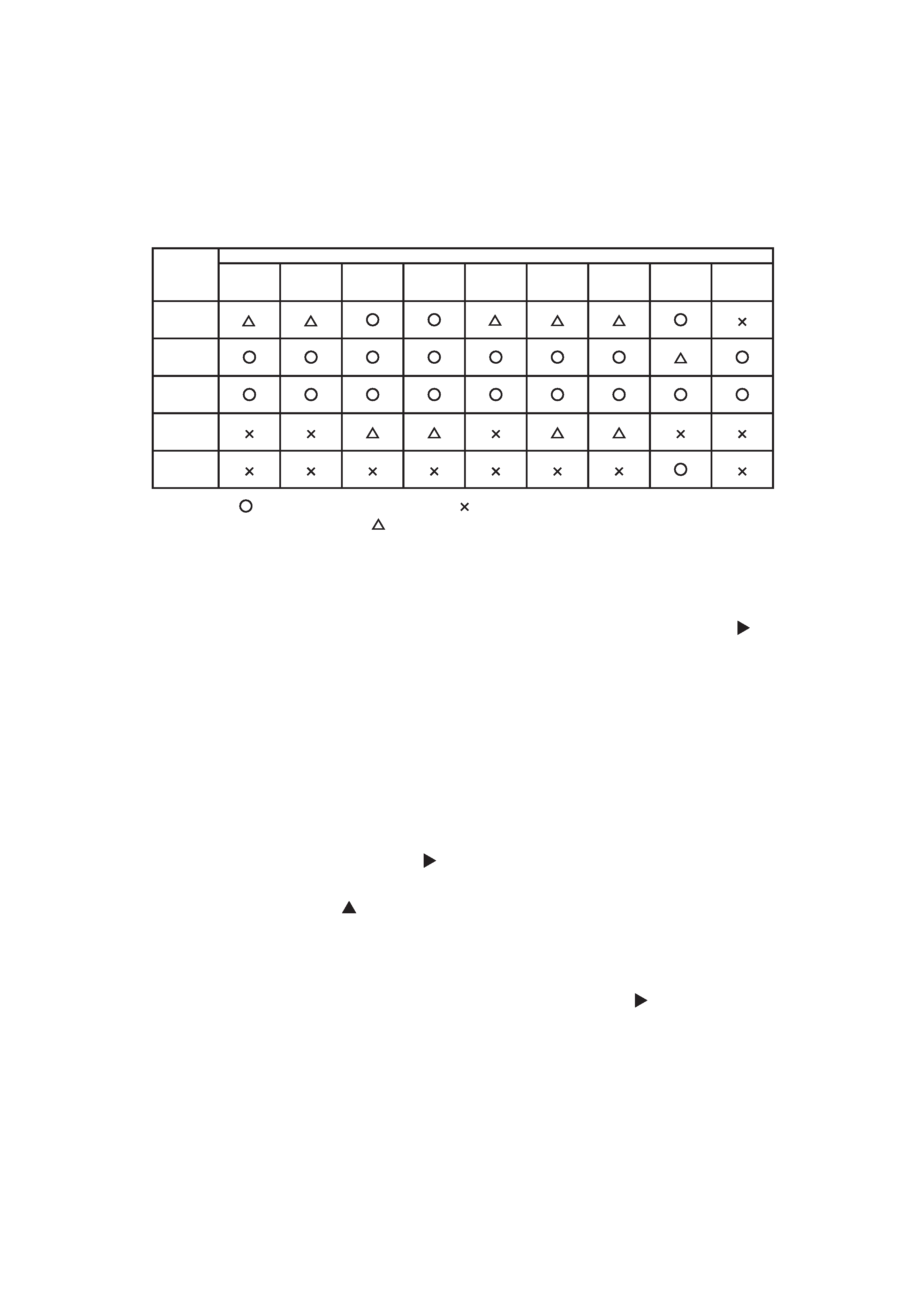
When any parts in the table 4-1 are changed, choose the proper adjusting items with the chart.
Table 4-1: Relation between the replaced part and adjustment
Replaced
part
Adjustment
Convergence
(Chap.4-2)
E-POS
(Chap.4-3)
Ghost
(Chap.4-4)
Flicker
(Chap.4-5)
NRSH
(Chap.4-6)
White
balance
(Chap.4-7)
Color
uniformity
(Chap.4-8)
AIR
SENSOR
(Chap.4-9)
IRIS
(Chap.4-10)
Dichroic
optics unit
LCD/LENS
prism
assembly
PWB
assembly
Main
Lamp
unit
assembly
PWB
assembly
Sensor
: means need for adjustment.
: means not need for djustment.
: means recommended.
4-1-2 Setting of condition before adjustment
1. Before starting adjustment, warim up projector
for about 10 minutes.
2. Set Zoom Wide to Max. And project an image
with more than 1m (40 inches) in diagonal size.
3. Set the lens position to the center, where you
feel click, using horizontal and vertical lens shift
dials.
4. Normalizing the video adjustment
Press the [MENU] button to display the Easy
menu. If Advance menu comes up, move to the
Easy menu.
Select RESET in the Easy menu and press [ ]
or [ENTER] button to open the RESET menu
window. Choose EXECUTE with [ ] button.
Note that no signal input may have the projector
reset its adjustments.
5. Select PICTURE > GAMMA in the Advanced
menu to set to DEFAULT1.
Note that PICTURE menu is not selectable with
no signal input displayed.
6. Select PICTURE > COLOR TEMP > CUSTOM
in the Advance menu, then press [ ] or [ENTER]
button to display the equalizing window. Set all
the values of OFFSET and GAIN in the window
to zero.
Caution: Before this performance, make a note
of your customer's adjustments, because the
data is overwritten.
7. Perform all adjustments from the FACTORY
MENU.
Perform the following operations to display the
FACTORY MENU.
a. Press the [MENU] button of remote control to
display the Easy menu. (If the Advance menu
appears, move to the Easy menu from EASY
MENU.)
b. Select the [RESET] in the Easy menu, and
then press the [ ] or [ENTER] button.
c. Next, press the [RESET] button one time.
And hold the [RESET] button for 3 seconds
or more (the FACTORY MENU will appear).