CAUTION:
Before servicing this chassis, it is important that the service technician read the "Safety
Precautions" and "Product Safety Notices" in this service manual.
ATTENTION:
Avant d'effectuer l'entretien du châassis, le technicien doit lire les «Précautions de sécurité»
et les «Notices de sécurité du produit» présentés dans le présent manuel.
VORSICHT:
Vor Öffnen des Gehäuses hat der Service-Ingenieur die ,,Sicherheitshinweise" und ,,Hinweise
zur Produktsicherheit" in diesem Wartungshandbuch zu lesen.
SERVICE MANUAL
MANUEL D'ENTRETIEN
WARTUNGSHANDBUCH
Data
contained
within
this
Service
manual is subject to alteration for
improvement.
Les données fournies dans le présent
manuel d'entretien peuvent faire l'objet
de modifications en vue de perfectionner
le produit.
Die
in
diesem
Wartungshandbuch
enthaltenen Spezifikationen können sich
zwecks Verbesserungen ändern.
MAY 2001
MULTIMEDIA LCD PROJECTOR
SM0515
SPECIFICATIONS AND PARTS ARE SUBJECT TO CHANGE FOR IMPROVEMENT
CONTENTS
FEATURES ..........................................................................................................................................................2
SPECIFICATIONS ...............................................................................................................................................2
ADJUSTMENT .....................................................................................................................................................3
SERVICE POINTS .............................................................................................................................................10
DISASSEMBLY DIAGRAM ................................................................................................................................15
REPLACEMENT PARTS LIST ...........................................................................................................................17
OPTION PARTS LIST........................................................................................................................................18
PJLC2001
PJ-LC2001
2
1. Features
High brightness, High resolution
Compact size, light weight for portability
RS-232C Communication
Complies with VESA DDC1/2B specifications
Auto-adjustment function
2. Specifications
Liquid crystal
panel
Lamp
Video input
RGB input
Drive system
Panel size
Number of pixels
System
Level
Video signal
Sync signal
Audio input
Speaker output
Power supply
Power consumption
Dimensions
Weight
Temperature range
Accessories
TFT active matrix
0.7 inches
800 (H) × 600 (V)
130W UHB
Composite
Y/C
NTSC, 4.43NTSC, PAL, M-PAL, PAL60, N-PAL or SECAM
Analog RGB input
0.7Vp-p (75
termination)
H/V separate
TTL level
200mVrms, 47k
1W (mono)
AC100~120V/2.0A, AC220~240V/0.9A
200W
289 (W) × 70 (H) × 210 (D) mm (Expect the foot adjuster)
2.38kg
Operation
: 0~35°C
Storage
: -20~60°C
Remote control transmitter × 1
RGB cable × 1
RCA Video cable × 1
S-video cable × 1
Audio cable (Stereo Mini) × 1
1.0Vp-p (75
termination)
0.3Vp-p (PAL/SECAM burst signal, 75
termination)
Y : 1.0Vp-p (75
termination)
C : 0.286Vp-p (NTSC burst signal, 75
termination)
POWER cord × 2
Battery (inside Remote control transmitter)× 1
Scart socket × 1
Carrying bag × 1
User's manual (with Safety Instructions)× 1
PJ-LC2001
3
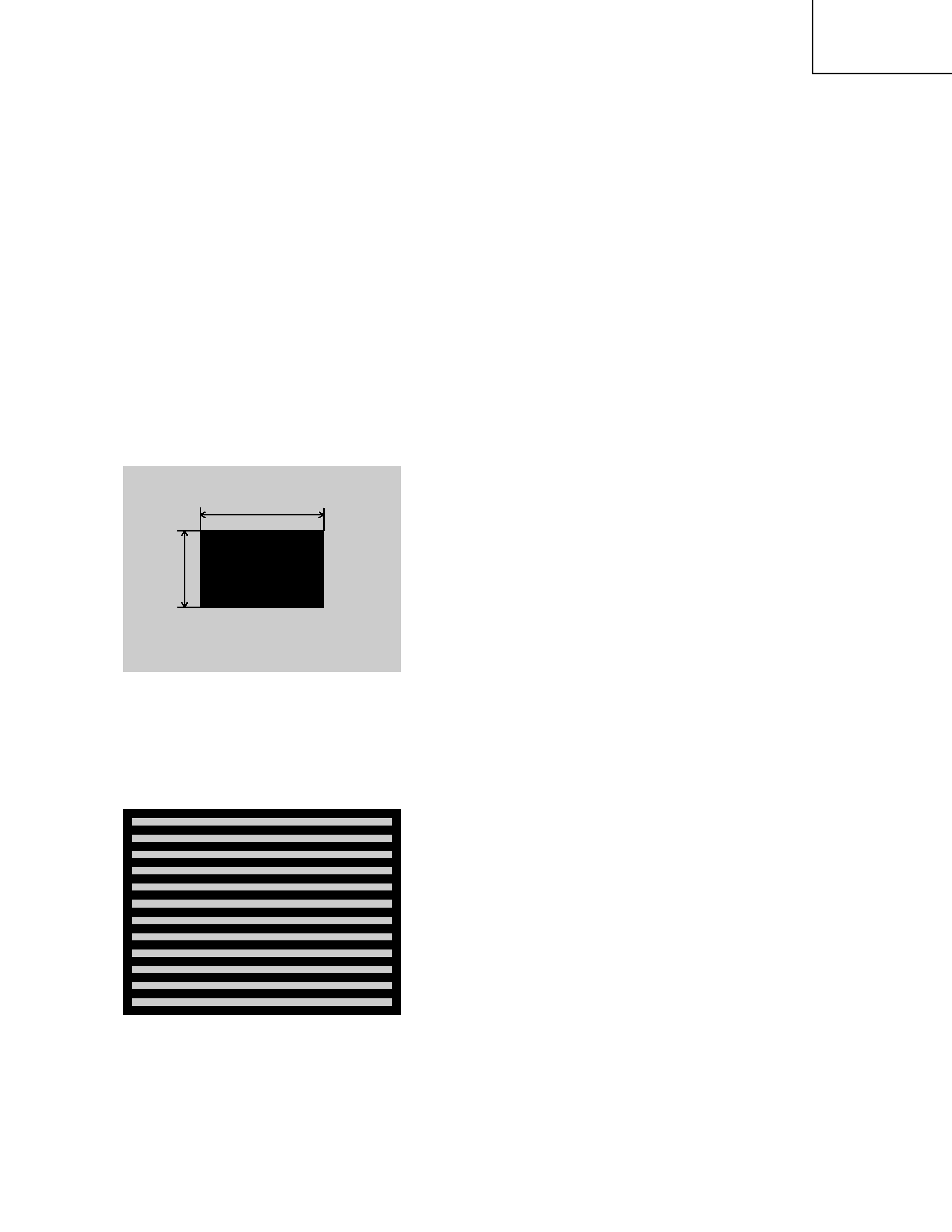
3 - 2 Ghost adjustment
Signals for internal adjustment
30%
30%
96/255
bit
0/255
bit
Adjustment procedure
1. Use DAC-P - GHOST-R: in the Adjustment menu to
adjust so that R color ghost is at a minimum.
(Return to adjustment value 0 from initial value 4,
then raise the value. When a ghost appears to the
left of a vertical line, reduce the value by 2 steps.)
2. In the same way, use DAC-P - GHOST-G: in the
Adjustment menu to adjust so that G color ghost is
at a minimum.
3. In the same way, use DAC-P - GHOST B: in the
Adjustment menu to adjust so that B color ghost is
at a minimum.
3 - 3 Flicker adjustment (V.COM adjustment)
Signals for internal adjustment
Adjustment procedure
1. Make this adjustment after completing the
adjustment in 3-2 Ghost adjustment.
2. Use DAC-P - V.COM - R: in the Adjust menu to
adjust so that the flicker at the center of the screen
is less than the flicker at the periphery.
(When the flicker is about the same across the
whole screen, adjust so that the flicker at the center
of the screen is somewhat less than elsewhere.)
3. In the same way, use DAC-P - V.COM - G: in the
Adjustment menu to adjust the G color flicker.
4. In the same way, use DAC-P - V.COM - B: in the
Adjustment menu to adjust the B color flicker.
3. Adjustment
3 - 1 Before adjusting
1. Before starting adjustment, warm up the projector
for about 10 min. (Blank white)
2. Set Zoom Wide to Max. and project an image a
distance of 40 inches.
3. Normalizing the video adjustment.
(Press the [MENU] button of the remote control
transmitter to display the Setup menu, then press
the [RESET] button.)
*note :The setup menu is not displayed on with no signal.
4. Perform all adjustments from the Adjustment menu.
Perform the following operations to display the
Adjustment menu.
a. Press the [MENU] button of the remote control
transmitter (the Setup menu will appear).
b. Next, press the [RESET] button for 5 sec. or
more (the Adjustment menu will appear).

PJ-LC2001
4
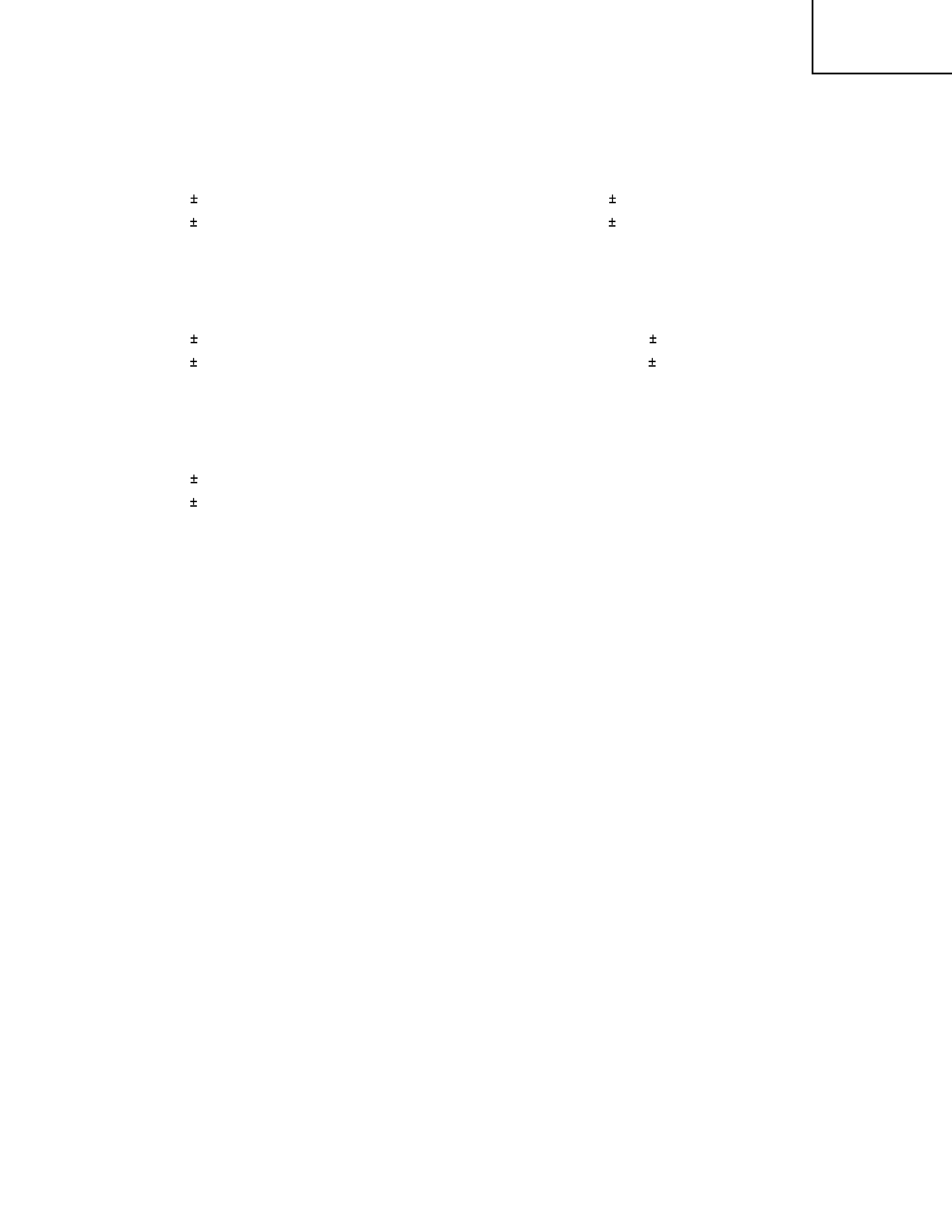
3 - 4 NRSH adjustment (vertical stripe adjustment)
Signals for internal adjustment
192
/255
bit
168
/255
bit
144
/255
bit
120
/255
bit
96
/255
bit
72
/255
bit
48
/255
bit
24
/255
bit
Adjustment procedure
1. Make this adjustment after completing the
adjustment in 3-3 Flicker adjustment.
2. Use DAC-P - NRSH - R: in the Adjust menu to
adjust so that the vertical lines spaced every 6 dots
are as inconspicuous as possible.
(Reduce the adjustment value when black stripes
appear in the 2nd or 3rd tone from the black side.
Note that when the adjustment value is lowered,
white stripes may appear in the 2nd or 3rd tone from
the bright side. Should this happen, adjust so that
the stripes are as inconspicuous as possible.)
3. In the same way, use DAC-P - NRSH - G: in the
Adjustment menu to adjust vertical stripes of G color.
4. In the same way, use DAC-P - NRSH - B: in the
Adjustment menu to adjust vertical stripes of B color.
3 - 5 White balance adjustment
Adjustment procedure 1
(when a color differential meter is used)
1. Perform these adjustments after the NRSH
adjustment described in Section 3-4.
2. First, adjust the G color.
3. Place the cursor on Slide Show in the Adjust menu
[A/D], press the [ ] key three times to display G
monochrome and adjust the illuminance at the
center of the screen. Make a note of the setting
(here assumed to be A [lx]). Press the MENU key
to return.
4. Use an SVGA (VESA60) timing signal to display
0.63 Vp-p G monochrome. Adjust Gamma 90%
and G: in the Adjust menu so that illuminance (Y)
at the center of the screen is adjusted as follows.
Y = A x 0.82 20 [lx]
5. Switch the signal to 0.52 Vp-p G monochrome.
Adjust Gamma, 75% and G: in the Adjust menu so
that illuminance (Y) at the center of the screen is
adjusted as follows.
Y = A x 0.55 20 [lx]
6. Switch the signal to 0.35 Vp-p G monochrome.
Adjust Gamma, 50% and G: in the Adjust menu so
that illuminance (Y) at the center of the screen are
adjusted as follows.
Y = A x 0.22 10 [lx]
7. Gamma 20% and 30% G: in the Adjust menu need
not be adjusted.
Set (20% G) : is (50% G) -20 steps.
Set (30% G) : is (50% G) -40 steps.
8. Switch the signal to 0 Vp-p black. Adjust Gamma,
0% and G: so that illuminance at the center of the
screen is as follows.
Y = A x 0.0022 0.1 [lx]
9. Gamma 3% G: in the Adjust menu need not be
adjusted.
Set 3% G : is 0% G + 0.6 x (20% G - 0% G).
10.Now, adjust the R and B colors.
11.Place the cursor on [A/D] - [SLIDE SHOW] in the
ADJUST menu and press the [ ] key once to
display a white screen. Then measure the color
coordinates at the center of the screen and take a
note of the setting (here assumed to be x1, y1).
Press the [MENU] key to return.
12.Switch the signal to 0.63 Vp-p white. Adjust
Gamma, 90%, R: and B: so that the color
coordinates (x, y) at the center of the screen take
on the following values.
x = (x1 + 0.282) /2 0.003
y = (y1 + 0.320) /2 0.005
PJ-LC2001
5
13.Switch the signal to 0.52 Vp-p white. Adjust
Gamma, 75%, R: and B: so that the color
coordinates (x, y) at the center of the screen take
on the following values.
x = 0.282 0.003
y = 0.320 0.005
14.Switch the signal to 0.35 Vp-p white. Adjust
Gamma, 50%, R: and B: so that the color
coordinates (x, y) at the center of the screen take
on the following values.
x = 0.280 0.003
y = 0.310 0.005
15.Switch the signal to 0.21 Vp-p white. Adjust
Gamma, 30%, R: and B: so that the color
coordinates (x, y) at the center of the screen take
on the following values.
x = 0.278 0.003
y = 0.300 0.005
16.Switch the signal to 0.14 Vp-p white. Adjust
Gamma, 20%, R: and B: so that the color
coordinates (x, y) at the center of the screen take
on the following values.
x = 0.276 0.003
y = 0.290 0.005
17.Switch the signal to 0.07 Vp-p black. Adjust
Gamma, 3%, R: and B: so that the color
coordinates (x, y) at the center of the screen take
on the following values.
x = (x1 - 0.040) 0.010
y = (y1 - 0.080) 0.020
18.Gamma 0% R and B : in the Adjust menu need not
be adjusted.
Set 0% R : is 3% R + 1.5 x (20% R - 3% R).
Set 0% B : is 3% B + 1.5 x (20% B - 3% B).
When the calculation value is minus, set the value
to " 0 ".
Adjustment procedure 2
1. Perform these adjustments after the NRSH
adjustment described in Section 3-4.
2. First, adjust the G color.
3. Use the SVGA (VESA60) timing signal to display
0.7 Vp-p G monochrome in the 16-tone grayscale.
4. Adjust gamma, 90% and G: to lower the 2nd tone
from the bright end of the grayscale then raise it
again slightly until the grayscale is clearly visible.
5. When you want to decrease the amount of black
(to improve the contrast), adjust Gamma, 0% and
G: in the Adjust menu. But make sure that the
black end of the spectrum does not become
distorted.
6. Then adjust colors R and B.
7. Use the SVGA (VESA60) timing signal to display
0.7 Vp-p white in the 16-tone grayscale .
8. Use Gamma, 90%, R: and B: in the Adjust menu to
adjust the color of the 3rd step from the white side
in the grayscale.
9. Adjust Gamma, 75%, R: and B: so that the color of
the 5th step from the white end of the gray scale
spectrum is set to optimum.
10.Adjust Gamma, 50%, R: and B: in the Adjust menu
so that the color at the center of the grayscale is
set to optimum.
11.Adjust Gamma, 30%, R: and B: in the Adjust menu
so that the 5th and 6th step colors from the dark
end of the spectrum are set to optimum.
12.Adjust Gamma, 20%, R: and B: so that the color of
the 4th step from the dark end of the gray scale
spectrum is set to optimum.
13.Adjust Gamma, 3%, R: and B: in the Adjust menu
so that the 2nd and 3rd step colors from the dark
end of the spectrum are set to optimum.
14.Adjust Gamma, 0%, R: and B: in the Adjust menu
so that the black portion of the grayscale of the
spectrum is set to optimum.