No. 0096E
SPECIFICATIONS AND PARTS ARE SUBJECT TO CHANGE FOR IMPROVEMENT
KHWS1W
KHWS1WUN
November 1999
DIGITAL RECEIVER
HITACHI CONSUMER PRODUCTS (S)
This documentation is applied to rescrictions for management, export and supply to overseas based on the Wassenaar
Arrangement.
CONTENTS
SPECIFICATIONS ..................................................................................................................................................... 2
SERVICE POINTS ..................................................................................................................................................... 3
ADJUSTMENTS ......................................................................................................................................................... 7
TROUBLESHOOTING ............................................................................................................................................... 10
BLOCK DIAGRAM OF ANTENNA AND TUNER UNIT ............................................................................................ 17
DATA OF MICROPROCESSOR ............................................................................................................................... 18
SEMICONDUCTORS ................................................................................................................................................. 24
WIRING DIAGRAM .................................................................................................................................................... 30
PRINTED WIRING BOARD ....................................................................................................................................... 31
METHOD OF REMOVED IC ..................................................................................................................................... 36
CIRCUIT DIAGRAM ................................................................................................................................................... 37
BLOCK DIAGRAM ..................................................................................................................................................... 41
EXPLODED VIEW ...................................................................................................................................................... 43
REPLACEMENT PARTS LIST .................................................................................................................................. 45
01/BKpg KH-WS1 cover
10/11/00, 1:42 PM
1
KH-WS1
2
SAFETY PRECAUTIONS
The following precautions should be observed when servicing.
1. Since many parts in the unit have special safety-related characteristics, always use genuine Hitachi's replacement
parts. Especially critical parts in the power circuit block should not be replaced with other makers. Critical parts
are marked with
in the circuit diagram and printed wiring board.
2. Before returning a repaired unit to the customer, the service technician must thoroughly test the unit to ascertain
that it is completely safe to operate without danger of electrical shock.
SPECIFICATIONS
· WS (WorldSpace digital broadcast) Section
Circuit system:
Digital Receiver
Broadcast method:
WorldStar 1 Method
Receiver frequency:
L-Band (1453.384-1490.644 MHz)
Input/Output terminals
Antenna input terminal
Type/Impedance:
F-type/50
Polarization voltage: LHCP 2.5-2.2 V
RHCP 3.3-2.8 V
Max. current supply: 70 mA
External terminal:
9-pin, for future expansion
WS antenna (Built-in, detachable type):
WorldStar 1 Method compatible
antenna
Gain: over 6 dBi
Dimensions: 150 x 33 x 156 mm
(w x h x d)
· Radio Section
Circuit system:
FM/MW/SW1/SW2 4-bands
Superheterodyne
Tuning range:
FM: 87.5 - 108 MHz
MW: 522 - 1620 kHz (9 kHz steps)
520 - 1620 kHz (10 kHz steps)
SW1:2.300-7.300 MHz
Meter band: 120, 90, 75, 60,
49, 41 m
SW2:9.500-26.100 MHz
Meter band: 31, 25, 21, 19, 16,
13, 11 m
Antennas:
FM/SW1/SW2: Telescopic antenna
(aerial)
MW: Built-in ferrite-core antenna
(aerial)
· General Specifications
Power supply:
AC: 110-127 V/220-240 V, 50/60 Hz
DC: 6 V
"D" cell or IEC R20 or equivalent x 4
(Optional)
DC input jack
Input voltage : DC 6 V + 30%,
10% (DC 7.8 V 5.4 V)
Current consumption: max. 400 mA
Power (mains) consumption: 5 W
Audio output:
3 W (PMPO)
300 mW (DC operation, 10% THD)
Speaker:
65 mm Cone/8
Output/Impedance:
Headphones (stereo)/
Suitable impedance: 8-100
Line out (stereo)/2.2 k
Battery life time:
30 hours over by using alkaline (LR20)
batteries.
12 hours over by using manganic
(R20P) batteries.
(Use HITACHI battery/Measured
method: EIAJ CP-2905A)
Dimensions:
240.5 x 162.5 x 64.5 mm
240.5 x 162.5 x 93 mm (w x h x d)
(including the WS antenna and handle)
Weight:
1.5 kg (without batteries),
1.9 kg (with batteries)
· Accessories
AC power cord:
1
AC plug adaptor:
1
F-type connector:
1 set (for making an extention coaxial
cable)
Waterproof cover:
1
Waterproof tape:
1
NOTE:
* Specifications are subject to change without notice.
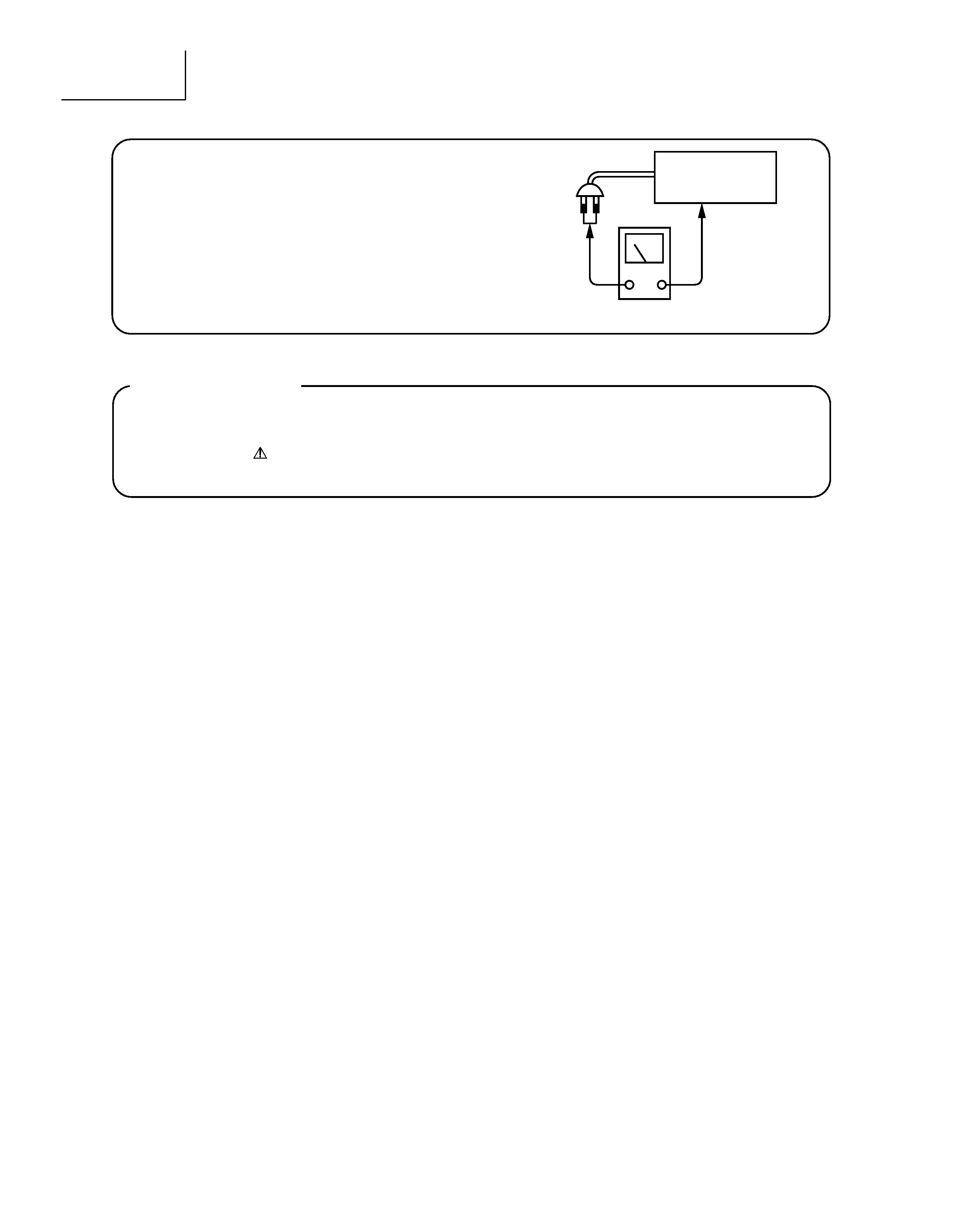
Check that exposed parts are acceptably insulated from
the supply circuit before returning the repaired instrument
to the customer.
· Checking method
Measure the resistance value between the both poles of
attachment cup (Power supply plug) and the exposed
parts (Parts such as Knob, Cover, etc. where the cus-
tomer is easy to touch.) and check that the resistance
value is 500 kohms or more.
INSTRUMENT
(Exposed part)
Insulation tester (DC 500V)
KH/Pg 02 (Spec)
10/11/00, 1:44 PM
2

KH-WS1
3
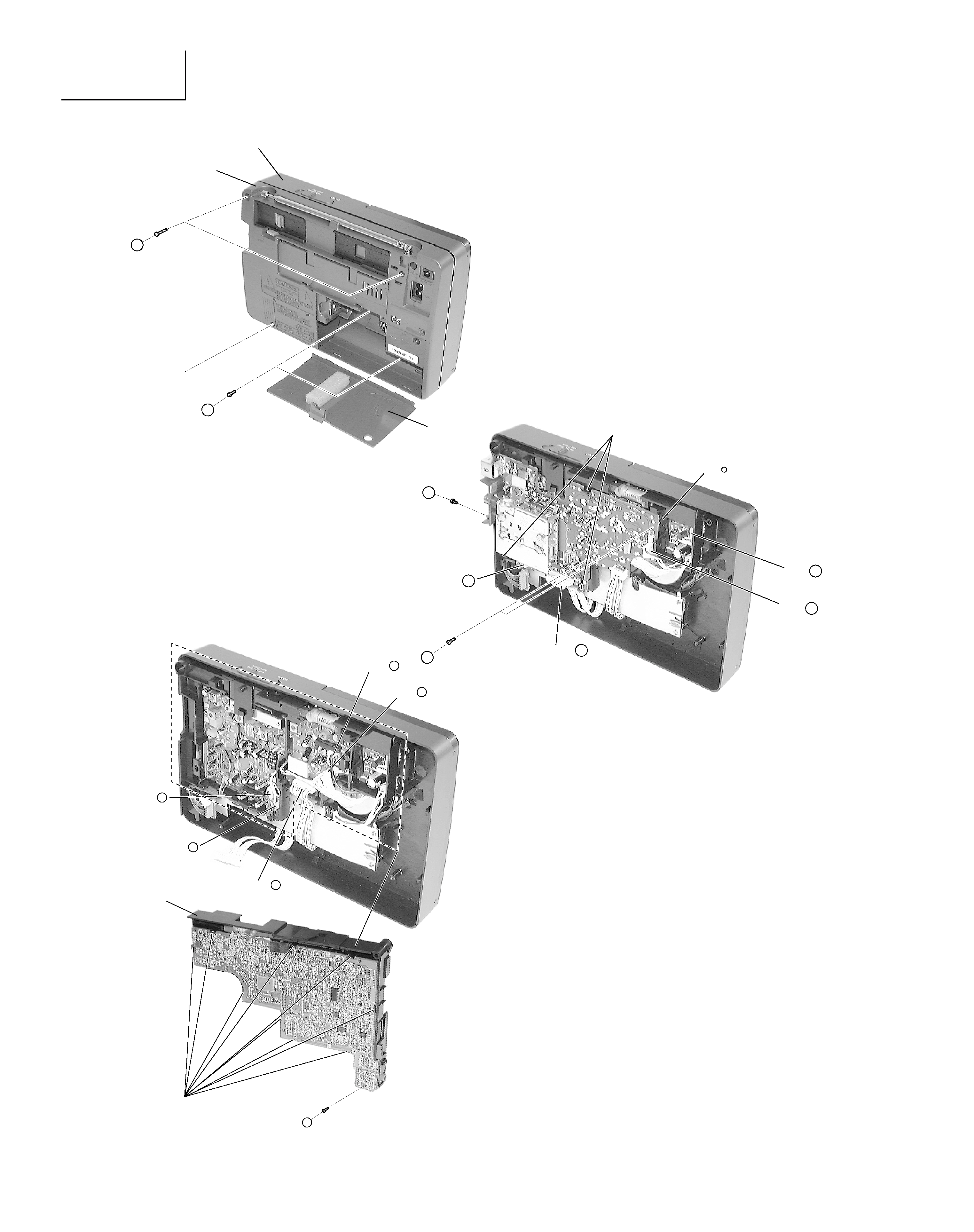
SERVICE POINTS
1. Removal of Back Case (Fig. 1)
(1) Remove 3 screws 1 from the back and 2 screws 2 inside the battery compartment.
(2) Detach the Antenna from the Ant }.
(3) Detach the connector A.
2. Removal of SATELLITE P.W.B. Board (Fig. 2)
(1) Detach all connectors B, C and D.
(2) Remove 1 screw 3 from the Satellite P.W.B. Board.
(3) Remove 2 screws 4 from the Satellite P.W.B. Board.
(4) Release the 3 catches and slide the Satellite P.W.B. Board away.
2. Removal of TUNER P.W.B. Board (Fig. 3)
(1) Detach 5 connectors E, F, G, H and I from the Tuner P.W.B. Board.
(2) Turn to the opposite side, remove 1 screw 5 from the Tuner P.W.B. Board.
(3) Detach 9 catches and separate the Tuner P.W.B. Board from the sub-chassis.
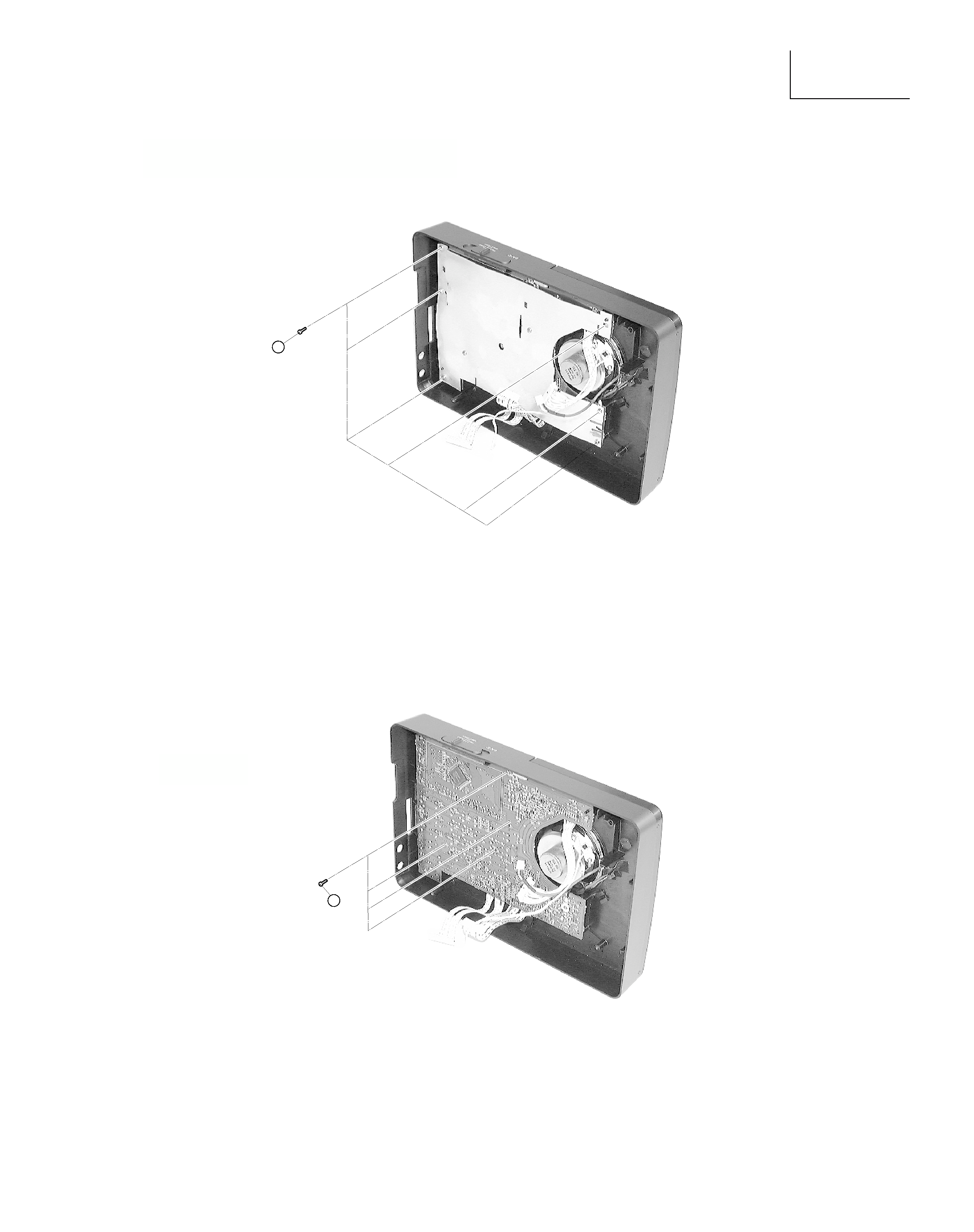
3. Removal of Insulator Pad (Fig. 4)
(1) Remove 6 screws 5 from the Insulator pad.
4. Removal of Main Board (Fig. 5)
(1) Remove 4 screws 6 from the Main Board.
5. Removal of Speaker (Fig. 6)
(1) Release one end of the metal pin that secures the speaker position.
(2) Slide out the speaker.
6. Removal of POWER SUPPLY P.W.B. Board (Fig. 7)
(1) Remove 4 screws 7 and detach 1 connector J from the Power Supply P.W.B. board.
7. Removal of ANTENNA P.W.B. Board (Fig. 7)
(1) Remove 1 screw 9 from the Antenna P.W.B. board.
(2) Gently pull the Antenna P.W.B. board outwards.
8. Removal of WS ANTENNA SUPPORT PLATE (Fig. 7)
(1) Remove the 6 screws 8 and pull the WS Antenna Support Plate away from the Back case.
KH/Pg 03 (Service Pt)
10/11/00, 2:23 PM
3
KH-WS1
4
Fig. 3
5
9 Catches
Connector H
Connector
Sub-Chassis
I
Connector E
Connector F
Connector G
Fig. 1
Fig. 2
1
2
Back case
Front case
Battery cover
4
Connector
3 Catches
Ant ·
3
A
Connector B
Connector C
Connector D
KH/Pg 04-06 (disassembling)
10/11/00, 1:47 PM
4
KH-WS1
5
Fig. 4
Fig. 5
5
6
KH/Pg 04-06 (disassembling)
10/11/00, 1:47 PM
5