SERVICE MANUAL
SPECIFICATIONS AND PARTS ARE SUBJECT TO CHANGE FOR IMPROVEMENT
Digital Media Division,Yokohama
DVD VIDEO RECORDER with VIDEO CASSETTE RECORDER
2005
July
SM0512
DV-RV8500E
PAL
PAL SECAM
DO NOT RESELL OR DIVERT IMPROPERLY.
DV-RV8500E(UK)

Contents - 1
Table of Contents
1 Safety Precaution for Repair ........... 1-1
1-1 Cautions ................................................. 1-1
1-2 Electrostatic Protection Measures .......... 1-2
1-3 Cautions When Handling DVD Drive ....... 1-2
1-4 Lead-Free Solder .................................... 1-3
1-5 Notes When Using Service Manual ........ 1-4
2 General Description ......................... 2-1
2-1 Overview ................................................ 2-1
2-1-1 Service method ................................... 2-1
2-1-2 Disc information ................................... 2-2
2-2 Features ................................................. 2-4
2-3 Specifications ......................................... 2-5
2-4 Major Differences from Previous Model .. 2-6
2-5 Function Differences from
Previous Model ....................................... 2-7
2-6 Names of Parts ....................................... 2-8
2-7 List of Abbreviations and Terms for DVD
Recorder ............................................... 2-12
3 Details of Servicing and
Troubleshooting ............................... 3-1
3-1 Details of Servicing ................................. 3-1
3-1-1 Removing Disc from Faulty Recorder ... 3-1
3-1-2 Removing Video Cassette from Faulty
Recorder ............................................... 3-1
3-1-3 Firmware .............................................. 3-2
3-1-4 Setting to defaults at the factory ........... 3-3
3-2 Troubleshooting ...................................... 3-4
3-2-1 Troubleshooting electronic system ........ 3-4
3-2-2 Troubleshooting mechanical block ...... 3-14
4 Disassembly and Reassembly ........ 4-1
4-1 Order of Disassembly ............................. 4-1
4-2 Cabinet Disassembly .............................. 4-1
(1) Top Cover ................................................. 4-1
(2) Front Panel ............................................... 4-2
(3) FAN Motor ................................................ 4-2
(4) SMPS P.C.B ............................................. 4-3
(5) Deck mechanism ...................................... 4-4
(6) TIMER P.C.B ............................................ 4-5
(7) VCR P.C.B ................................................ 4-5
(8) DVD multi-drive ........................................ 4-6
(9) VDR, JACK and KEY P.C.Bs .................... 4-6
4-3 Deck Mechanism Parts Locations ........... 4-7
4-4 Deck Mechanism Disassembly ................ 4-8
(1) Drum assembly ........................................ 4-8
(2) Top plate ................................................... 4-9
(3) CST holder assembly ............................... 4-9
(4) F/L rack gear assembly ............................ 4-9
(5) Door opener ............................................. 4-9
(6) F/L arm assembly ..................................... 4-9
(7) S/W lever assembly .................................. 4-9
(8) L/D motor assembly ............................... 4-11
(9) Wheel gear ............................................. 4-11
(10) F/E head .............................................. 4-11
(11) A/C head assembly .............................. 4-11
(12) T brake assembly ................................. 4-12
(13) Tension arm assembly .......................... 4-12
(14) S reel and T reel ................................... 4-12
(15) P4 base assembly ................................ 4-13
(16) Lid opener ............................................ 4-13
(17) Pressure arm assembly ....................... 4-13
(18) Take-up arm ......................................... 4-13
(19) Capstan supporter ............................... 4-14
(20) Capstan belt and capstan motor ........... 4-14
(21) F/R lever ............................................... 4-14
(22) D37 clutch assembly ............................ 4-14
(23) Driver gear and cam gear ..................... 4-15
(24) Sector gear .......................................... 4-15
(25) Capstan brake assembly ...................... 4-15
(26) Slider plate ........................................... 4-15
(27) Tension lever ........................................ 4-15
(28) Spring lever .......................................... 4-15
(29) Brake lever ........................................... 4-15
(30) P2 gear assembly and
P3 gear assembly ................................. 4-16
(31) P2 base assembly and
P3 base assembly ................................ 4-16
(32) Loading base ........................................ 4-16
(33) Tension base ........................................ 4-17
(34) Jog idler arm assembly ........................ 4-17
4-5 Checking Mode after Reassembling Deck
Mechanism ........................................... 4-18

Contents - 2
5 Adjustment / Maintenance ............... 5-1
5-1 Set-up for Adjustment ............................. 5-1
5-2 VCR Electrical Adjustment ..................... 5-2
5-2-1 Head switching adjustment ................... 5-2
5-3 Deck Mechanism Tape Transport System
Adjustment ............................................. 5-3
5-3-1 Guide roller height adjustment ................. 5-3
5-3-2 A/C head adjustment ............................ 5-4
5-3-3 X-value adjustment ............................... 5-5
5-3-4 Adjustments after replacing
drum assembly ..................................... 5-5
5-3-5 Check after adjustment ........................ 5-6
5-3-6 Method of setting the mechanism to
loading status without inserting tape ..... 5-6
5-3-7 Reel torques ......................................... 5-7
5-4 Maintenance ............................................ 5-8
5-4-1 Maintenance and inspection ................. 5-8
5-4-2 Lubricating oil and greasing ................ 5-10
6 Exploded View and Parts List .......... 6-1
6-1 Exploded Views ...................................... 6-1
6-1-1 Cabinet Section ................................... 6-1
6-1-2 F / L Mechanism .................................. 6-2
6-1-3 Deck Mechanism Section - Top view ... 6-3
6-1-4 Deck Mechanism Section - Bottom view 6-4
6-2 Parts List ................................................. 6-5
6-2-1 Mechanical Parts List ........................... 6-5
6-2-2 Electrical Parts List ............................... 6-6
S Schematic, Wiring Diagrams .......... S-1
S-1 Wiring Diagram ....................................... S-1
S-2 S.M.P.S Schematic Diagram ................... S-2
S-3 SYSTEM Schematic Diagram(VCR P.C.B) S-3
S-4 TUNER Schematic Diagram(VCR P.C.B) .. S-4
S-5 A/V Schematic Diagram(VCR P.C.B) ...... S-5
S-6 Hi-Fi Schematic Diagram(VCR P.C.B) .... S-6
S-7 REAR JACK Schematic Diagram
(VCR P.C.B) ............................................ S-7
S-8 TIMER,KEY Schematic Diagrams .......... S-8
S-9 JACK Schematic Diagram ...................... S-9
S-10 A/V,SYSTEM Circuit Waveforms ......... S-10
S-11 CIRCUIT VOLTAGE CHART ................ S-11
C Circuit Board Diagrams .................. C-1
C-1 VCR Circuit Board Diagram ................... C-1
C-2 S.M.P.S Circuit Board Diagram .............. C-3
C-3 JACK Circuit Board Diagram ................. C-4
C-4 TIMER Circuit Board Diagram ............... C-4
C-5 KEY Circuit Board Diagram ................... C-4
B Block Diagrams ............................... B-1
B-1 S.M.P.S Circuit Block Diagram ................ B-1
B-2 VIDEO Circuit Block Diagram ................. B-2
B-3 AUDIO Circuit Block Diagram ................. B-3
B-4 SYSTEM Circuit Block Diagram .............. B-4
B-5 VIDEO I/O Circuit Block Diagram ........... B-5
1 - 1
Safety Precaution for Repair
1
1-1 Cautions
CAUTION
There is a high-voltage section inside the DVD video
recorder. When repairing or inspecting it, take great care
to prevent electric shock: Use an isolating transformer,
wear gloves, etc.
Many electrical and mechanical parts have special safety-related characteristics. These are often not
evident from visual inspection nor can the protection afforded by them necessarily be obtained by using
replacement components rated for a higher voltage, wattage, etc. Replacement parts which have these
special safety characteristics are identified in this Service Manual. Electrical components having such
features are identified by marking with a
on the schematics and the parts list in this Service Manual.
The use of a substitute replacement component which does not have the same safety characteristics as
the HITACHI recommended replacement one, shown in the parts list in this Service Manual, may create
shock, fire, or other hazards. Product safety is continuously under review and new instructions are
issued from time to time. For the latest information, always consult the current HITACHI Service Manual.
A subscription to, or additional copies for, HITACHI Service Manual may be obtained at a nominal
charge from HITACHI SALES CORPORATION.
PRODUCT SAFETY NOTICE
CAUTION
This product contains a laser diode of
higher class than 1. To ensure contin-
ued safety, do not remove any covers
or attempt to gain access to the in-
side of the product. Refer all servicing
to qualified personnel.
1 - 2
Safety Precaution for Repair > Electrostatic Protection Measures / Cautions When Handling DVD Drive
1-2 Electrostatic Protection Measures
Semiconductor components can be damaged by static electricity charged on clothes, human body,
etc. Take great care when handling components to avoid electrostatic damage, and perform
servicing in an environment where grounding is complete.
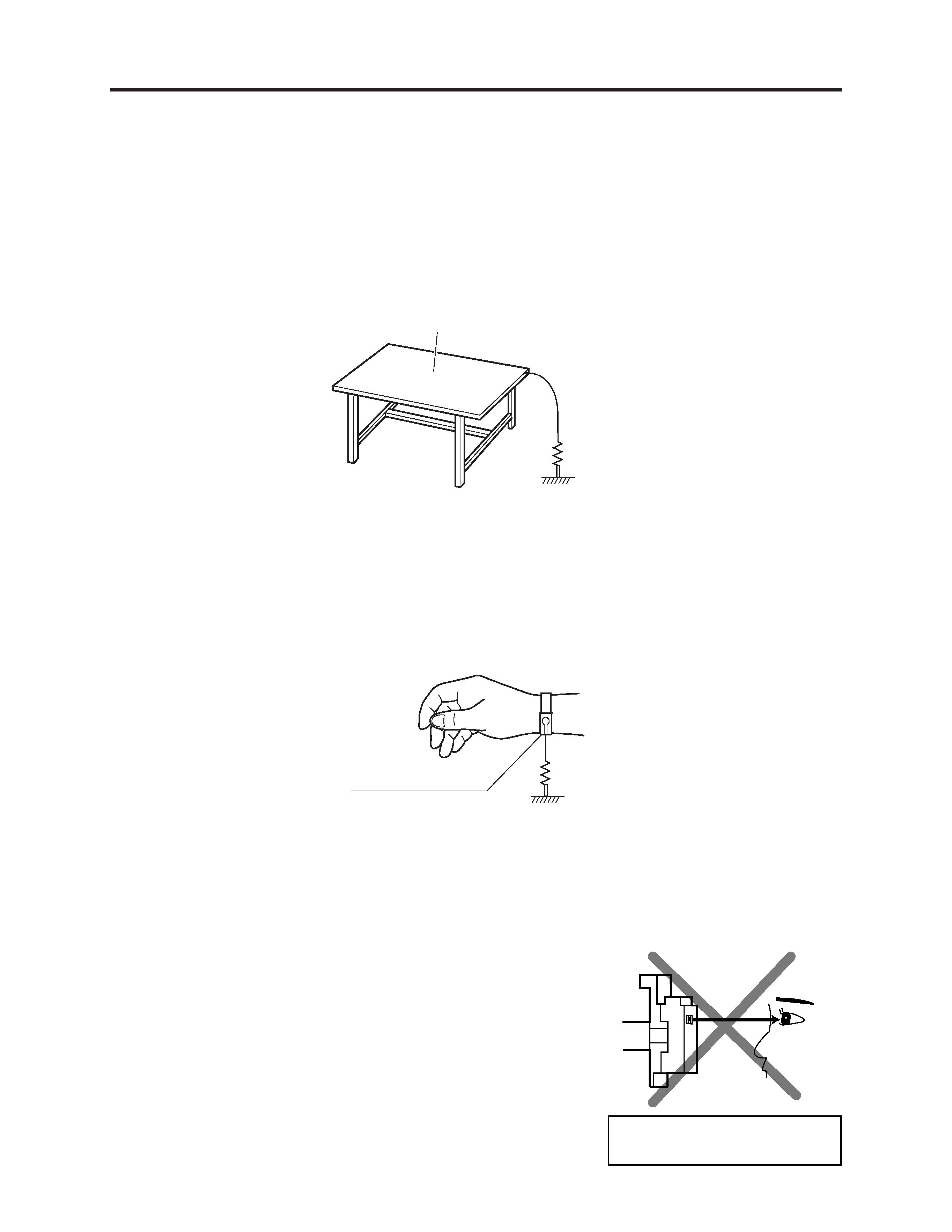
(1) Grounding work bench
Lay out an antistatic mat on work bench, and then use the ground plate to ground the work bench.
Antistatic mat
Ground
1M ohm
1M ohm
Antistatic wrist strap
1-3 Cautions When Handling DVD Drive
The optical pickup in DVD drive has a high precision structure: Be sure to observe the following
cautions.
1) Do not subject optical pickups to any severe vibrations or
impact during movement, installation or disassembly.
2) When performing repair work, do not perform disassembly
any further than that described in this manual.
3) Never turn the semi-variable resistors for adjustment in
optical pickup or DVD drive.
4) NEVER look into the objective lens in optical pickup or
directly view the laser light: You could lose your eyesight.
Do not directly look at laser light
from pickup.
(2) Grounding human body
Use an antistatic wrist strap to discharge any static electricity charged on the body. Also, use a
tester for wrist strap to make sure that the wrist strap is working normally. Note, however, that
static electricity charged on clothes will not be discharged by wrist strap: Therefore do not allow
your clothes to touch the semiconductor components.