TK
No.9010E
SPECIFICATIONS AND PARTS ARE SUBJECT TO CHANGE FOR IMPROVEMENT
DVD PLAYER
SERVICE MANUAL
2000
September
Digital Media Products Division, Tokai
DV-P705E
DV-P705E(UK)
DV-P705U
DVD/CD/VIDEO CD PLAYER D
V-P705
VIRTUAL
SURROUND
OPEN/CLOSE
DISC
NAVIGATION
TOP MENU
PUSH ENTER
MENU
STOP
SKIP
FWD
REV
PLAY/
PAUSE
/I
PRODUCT SAFETY NOTICE
Many electrical and mechanical parts have special safety-related characteristics. These are often not evident from visual
inspection nor can the protection afforded by them necessarily be obtained by using replacement components rated for a
higher voltage, wattage, etc. Replacement parts which have these special safety characteristics are identified in this
Service Manual. Electrical components having such features are identified by marking with a
on the schematics and
the parts list in this Service Manual. The use of a substitute replacement component which does not have the same
safety characteristics as the HITACHI recommended replacement one, shown in the parts list in this Service Manual, may
create shock, fire, or other hazards. Product safety is continuously under review and new instructions are issued from
time to time. For the latest information, always consult the current HITACHI Service Manual. A subscription to, or
additional copies for, HITACHI Service Manual may be obtained at a nominal charge from HITACHI SALES
CORPORATION.
LASER RADIATION
Do not stare at
the laser beam
CAUTION
NOTICE:
Comply with all cautions and safety related notes
located on or inside the cabinet and on the chassis.
1. When replacing a chassis in the instrument, all the
protective devices must be put back in place, such as
barriers, non-metallic knobs, adjustment and
compartment covers/shields, isolation resistors/
capacitors, etc.
2. When service is required, observe the original lead-
ress. Extra precautions should be taken to assure
correct lead dress in the high voltage circuit.
3. Always use the manufacturer's replacement
components. Especially critical components as
indicated on the circuit diagram should not be
replaced by other manufacturer's. Furthermore,
where a short-circuit has occurred, replace those
components that indicate evidence of overheating.
4. Before returning an instrument to the customer, the
service technician must thoroughly test the unit to be
certain that it is completely safe to operate without
danger of electrical shock, and be sure that no
protective device built into the instrument by the
manufacturer has become defective or inadvertently
defeated during servicing. Therefore, the following
checks should be performed for the continued
protection of the customer and service technician.
Leakage Current Cold Check
With the AC plug removed from the AC120V, 60Hz
source, place a jumper across the two plug prongs.
Turn the AC power switch on. Using an insulation
tester (DC500V), connect one lead to the jumpered
AC plug and touch the other lead to exposed metal
parts (antennas, screwheads, metal overlays,
control shafts, etc.), particularly any exposed metal part
having a eturn path to the chassis. Exposed metal
parts having a return path to the chassis should have a
minimum resistor reading of 0.3 Mohm and a maximum
resistor reading of 5 Mohm. Any resistor value below
or above this range indicates an abnormality which
requires corrective action. Exposed metal parts not
having a return path to the chassis will indicate an open
circuit.
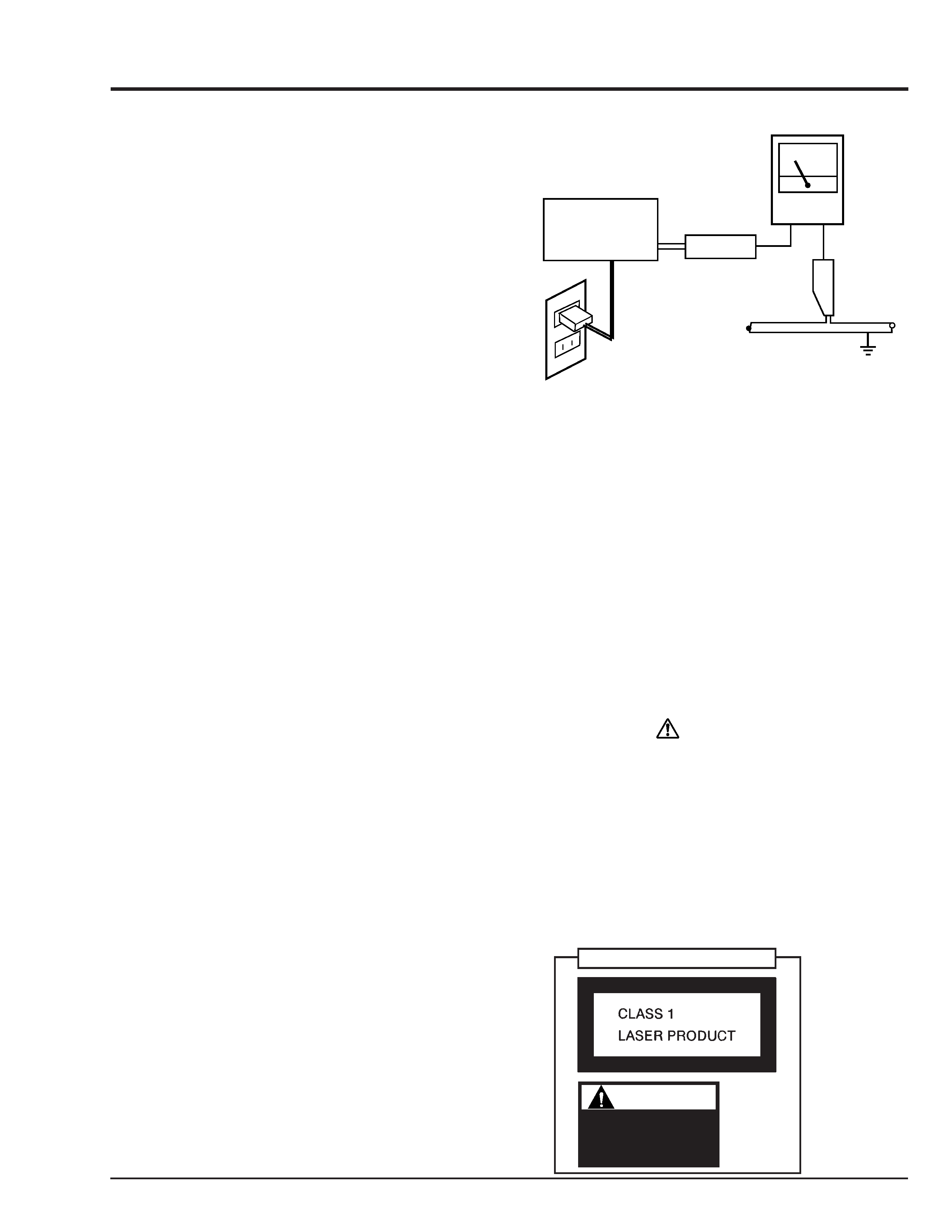
Leakage Current Hot Check
Plug the AC line cord directly into a AC120V, 60Hz
outlet (do not use an isolation transformer for this
check).
Turn the AC power switch on. Using a "Leakage
Current Tester", measure for current from all
exposed metal parts of the cabinet (antennas,
screwheads, metal overlays, control shaft, etc.),
particularly an exposed metal part having a return
path to the chassis, to a known ground (earth) (water
pipe, conduit, etc.). Any current measured must not
exceed 0.5 mA.
SAFETY PRECAUTIONS
AC Leakage Test
ANY MEASUREMENTS NOT WITHIN THE LIMITS
OUTLINED ABOVE ARE INDICATIVE OF A POTENTIAL
SHOCK HAZARD AND MUST BE CORRECTED
BEFORE RETURNING THE UNIT TO THE CUSTOMER.
PRODUCT SAFETY NOTICE
Many electrical and mechanical parts have special safety-
related characteristics. These are often not evident from
visual inspection nor can the protection afforded by them
necessarily be obtained by using replacement
components rated for a higher voltage, wattage, etc.
Replacement parts which have these special safety
characteristics are identified in this Service Manual.
Electrical components having such features are identified
by marking with a
on the schematics and the parts list
in this Service Manual. The use of a substitute
replacement component which does not have the same
safety characteristics as the HITACHI recommended
replacement one, shown in the parts list in this Service
Manual, may create shock, fire, or other hazards. Product
safety is continuously under review and new instructions
are issued from time to time. For the latest information,
always consult the current HITACHI Service Manual. A
subscription to, or additional copies for, HITACHI Service
Manual may be obtained at a nominal charge from
HITACHI SALES CORPORATION.
DEVICE
UNDER TEST
(READING
SHOULD NOT
BE ABOVE
0.5mA)
LEAKAGE CURRENT
TESTER
TEST ALL EXPOSED
METAL SURFACES
2-WIRE CORD
ALSO TEST WITHPLUG
REVERSED(USING AC
ADAPTER PLUG AS
REQUIRED)
GROUND
(EARTH)
LASER RADIATION
Do not stare at
the laser beam
CAUTION
Notes When Using Service Manual
The following shows the contents to be noted when using service manual:
1. Value units used in parts list
This table shows locations of each part on circuit board
diagrams. The locations are indicated using the guide
scales on the external lines of diagrams.
1) One diagram indicated for each board
The values, dielectric strength (power capacitance) and
tolerances of the resistors (excluding variable resistors)
and capacitors are indicated in the schematic diagrams
using abbreviations.
[Resistors]
Certain symbols are indicated below for value units of
resistors, capacitors and coils in parts list. When you read
them note the following regular indications:
Indication in list
Regular indication
KOHM ........................................... k
UF ................................................. µF
PF ................................................. pF
UH ................................................. µH
MH ............................................... mH
Parts
Resistor
Capacitor
Coil
2) Two diagrams indicated for each board
2. Values in schematic diagrams
Item
Value
Tolerance
Power
capacitance
Indication
No indication ...................................
K ................................................... k
M .................................................. M
No indication ............................. ±5%
(All tolerances other than ±5% are
indicated in schematic diagrams)
No indication ............................ 1/8W
(1/16W for leadless resistors without
indication)
All capacitances other than the above
are indicated in schematic diagrams.
[Capacitors]
Item
Value
Dielectric
strength
Indication
No indication ................................. µF
P ................................................... pF
No indication .............................. 50V
(All dielectric strengths other than 50V
are indicated in schematic diagrams)
Item
Value
Indication
µ .................................................... µH
m .................................................. mH
[Coils]
3. Identifications of sides A/B in
circuit board diagrams
1) Board having a pattern on one side and parts on
both sides.
Side A:
Shows discrete parts, viewed from the
pattern side.
Side B:
Shows leadless parts, viewed from the
pattern side.
2) Board having patterns on both sides and parts on
both sides.
Side A:
Shows parts and patterns which can be
seen when the case is opened.
Side B:
Shows parts and the pattern on the back of
side A.
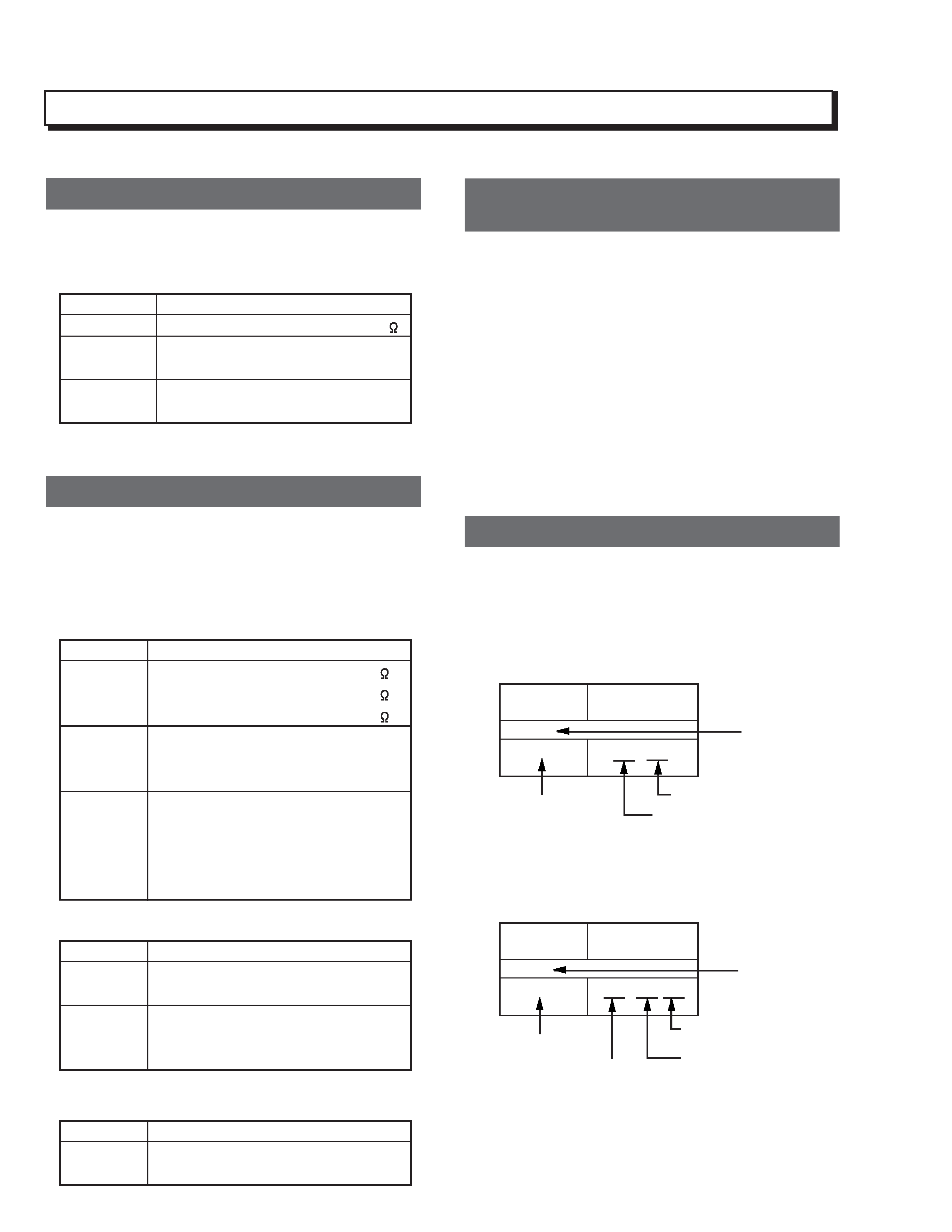
4. Table for indexing locations of parts
Parts
Location
2
A
Symbol
No.
IC
IC1201
Type of part
Zone "A" on board diagram
Circuit No.
Zone "2" on board diagram
Parts
Location
A - 2
A
Symbol
No.
IC
IC1201
Zone "2" on board
diagram
A: Shows side A
B: Shows side B
Zone "A" on board
diagram
Type of part
Circuit No.
CONTENTS
CHAPTER 1
GENERAL INFORMATION
1. Specifications ............................................................. 1-1
2. Comparison with Previous Model ............................... 1-2
3. Troubleshooting .......................................................... 1-4
3-1. VIDEO CIRCUIT .................................................... 1-4
3-2. AUDIO CIRCUIT .................................................... 1-5
4. Self-Diagnosis Function ............................................. 1-6
5. Instructions on Use ..................................................... 1-9
CHAPTER 2
DISASSEMBLY
1. Before Starting Disassembly ...................................... 2-1
2. Disassembly Method .................................................. 2-1
Parts Hierarchy Chart ................................................. 2-1
Disassembly Procedure Diagrams ............................. 2-2
2-1. Top cover .............................................................. 2-2
2-2. Tray panel, Front panel,
FSW board and MVR board ................. 2-3
2-3. Rear panel ............................................................. 2-4
2-4. VID board and REG board .................................... 2-5
2-5. AUD board and DEC board ................................... 2-5
2-6. DVD-ROM and Bottom cover ................................ 2-6
CHAPTER 3
EXPLODED VIEW
1. CABINET SECTION ................................................... 3-1
CHAPTER 4
REPLACEMENT PARTS LIST
1. MECHANICAL PARTS LIST ...................................... 4-1
SCHEMATIC, CIRCUIT BOARD
CHAPTER 5
AND BLOCK DIAGRAM
CONNECTION DIAGRAM .............................................. 5-1
SCHEMATIC/CIRCUIT
BOARD
FRONT SWITCH[FSW] ...................................... 5-3 / 5-23
POWER SWITCH[MVR] ..................................... 5-5 / 5-23
VIDEO JACK[VID] ............................................... 5-6 / 5-20
AUDIO JACK[AUD] ............................................. 5-7 / 5-21
REGURATOR[REG] ........................................... 5-9 / 5-25
DECK-1[DEC] .................................................. 5-11 / 5-16
DECK-2[DEC] .................................................. 5-13 / 5-16
BLOCK DIAGRAM ........................................................ 5-27