
TECHNICAL SPECIFICATIONS
SPÉCIFICATIONS TECHNIQUES
TECHNICAL SPECIFICATIONS
December 1998
No. 0201
DVP2E
SERVICE MANUAL
MANUEL D'ENTRETIEN
WARTUNGSHANDBUCH
CAUTION:
Before servicing this chassis, it is important that the service technician read
the "Safety Precautions"and "Product Safety Notices"in this service manual.
ATTENTION:
Avant d'effectuer l'entretien du châassis, le technicien doit lire les
«Précautions de sécurité» et les «Notices de sécurité du produit» présentés
dans le présent manuel.
VORSICHT:
Vor Öffnen des Gehäuses hat der Service-Ingenieur die ,,Sicherheitshinweise"
und ,,Hinweise zur Produktsicherheit"in diesem Wartungshandbuch zu lesen.
Data contained within this Service
manual is subject to alteration for
improvement.
Les données fournies dans le
présent
manuel
d'entretien
peuvent
faire
l'objet
de
modifications
en
vue
de
perfectionner le produit.
Die in diesem Wartungshandbuch
enthaltenen
Spezifikationen
können
sich
zwecks
Verbesserungen ändern.
DV-P2E
DVD PLAYER
1. SAFETY INFORMATION ...................................... 2
2. EXPLODED VIEWS AND PARTS LIST ................ 3
3. SCHEMATIC DIAGRAM ..................................... 10
4. PCB CONNECTION DIAGRAM .......................... 24
5. PCB PARTS LIST ............................................... 33
6. ADJUSTMENT .................................................... 38
CONTENTS
7. GENERAL INFORMATION ................................ 46
7.1 DISASSEMBLY ........................................... 46
7.2 BLOCK DIAGRAM ........................................ 47
8. PANEL FACILITIES AND SPECIFICATIONS .... 48
THIS MANUAL IS APPLICABLE TO THE FOLLOWING MODEL.
· Refer to the service guide for DV-P2E.
IC information is described in the service guide.
STANDBY
FL OFF
0
7
1
4¡ ¢
£¥8
'
DIGITAL VIDEO
96 kHz
ANGLE
TITLE
CHP/TRK
REMAIN TOTAL
GUI
DOLBY
DIGITAL
with
LAST MEMORY
POWER
--OFF_STANDBY/ON
DVD PLAYER
ÛN¿<x
l
e
d
o
M
t
n
e
m
e
r
i
u
q
e
R
r
e
w
o
P
l
a
n
o
i
g
e
R
e
d
o
c
n
o
i
t
c
i
r
t
s
e
r
E
2
P
-
V
D
V
0
4
2
0
2
2
C
A
2
2
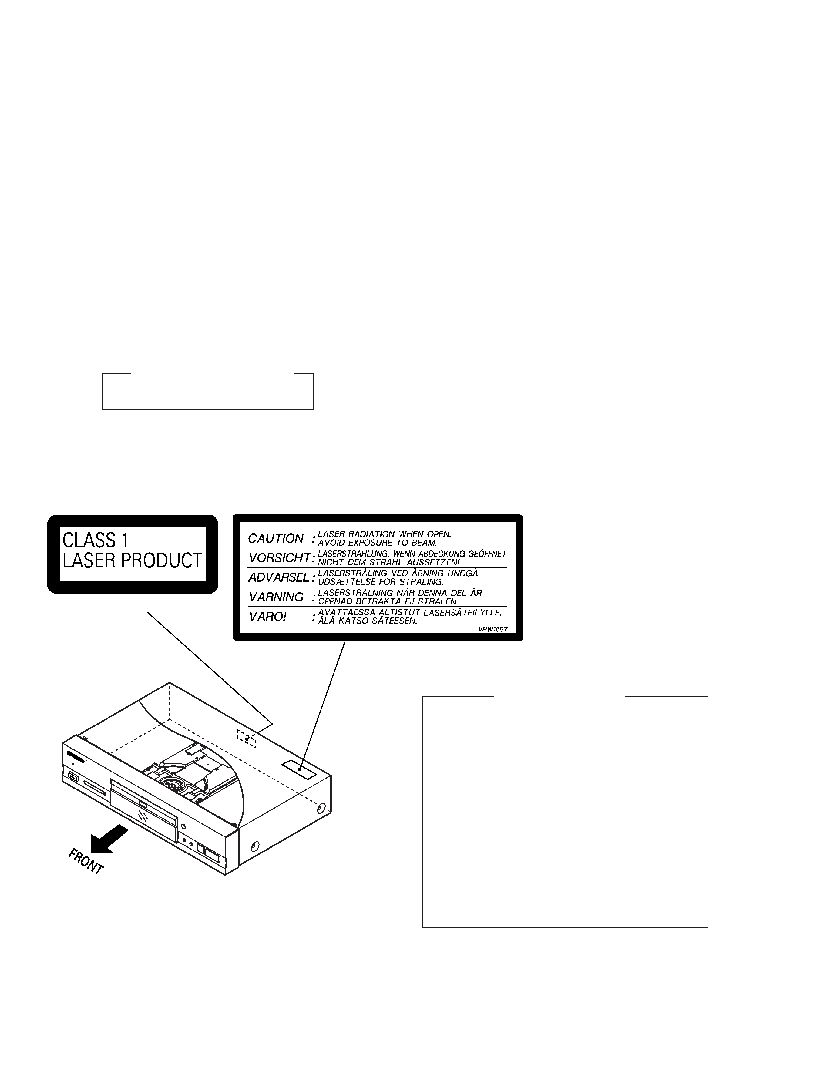
LABEL CHECK
IMPORTANT
THIS HITACHI APPARATUS CONTAINS
LASER OF CLASS 1.
SERVICING OPERATION OF THE APPARATUS
SHOULD BE DONE BY A SPECIALLY
INSTRUCTED PERSON.
LASER DIODE CHARACTERISTICS
MAXIMUM OUTPUT POWER : 7 mw
WAVELENGTH : 650 nm
Additional Laser Caution
1. Inside detection switch (S201 on the INSB assy) and loading-
status detection switch (S301 on the LOSB assy) are detected
by the microprocessor (IC501 in the DVDM assy).
· To permit the laser diode to oscillate, it is required to set the
inside detection switch for the inside position (S201 : ON) and to
set the loading-status detection switch for the clamp position (the
center terminal of S301 is shorted to +5V). The laser diode
oscillation will continue if pin 13 of IC101 is shorted to +5V (fault
condition) in the DVDM assy.
In the test mode
, the laser diode oscillates when microproces-
sor detects a PLAY signal, or when the PLAY key is pressed
(S107 ON in the FLKB assy), with the above requirements satis-
fied.
2. When the cover is open, close viewing through the objective lens
with the naked eye will cause exposure to the laser beam.
: Refer to page 40.
(Printed on the Rear Panel)
1. SAFETY INFORMATION
This service manual is intended for qualified service technicians ; it is not meant for the casual do-it-
yourselfer. Qualified technicians have the necessary test equipment and tools, and have been trained
to properly and safely repair complex products such as those covered by this manual.
Improperly performed repairs can adversely affect the safety and reliability of the product and may
void the warranty. If you are not qualified to perform the repair of this product properly and safely, you
should not risk trying to do so and refer the repair to a qualified service technician.
3
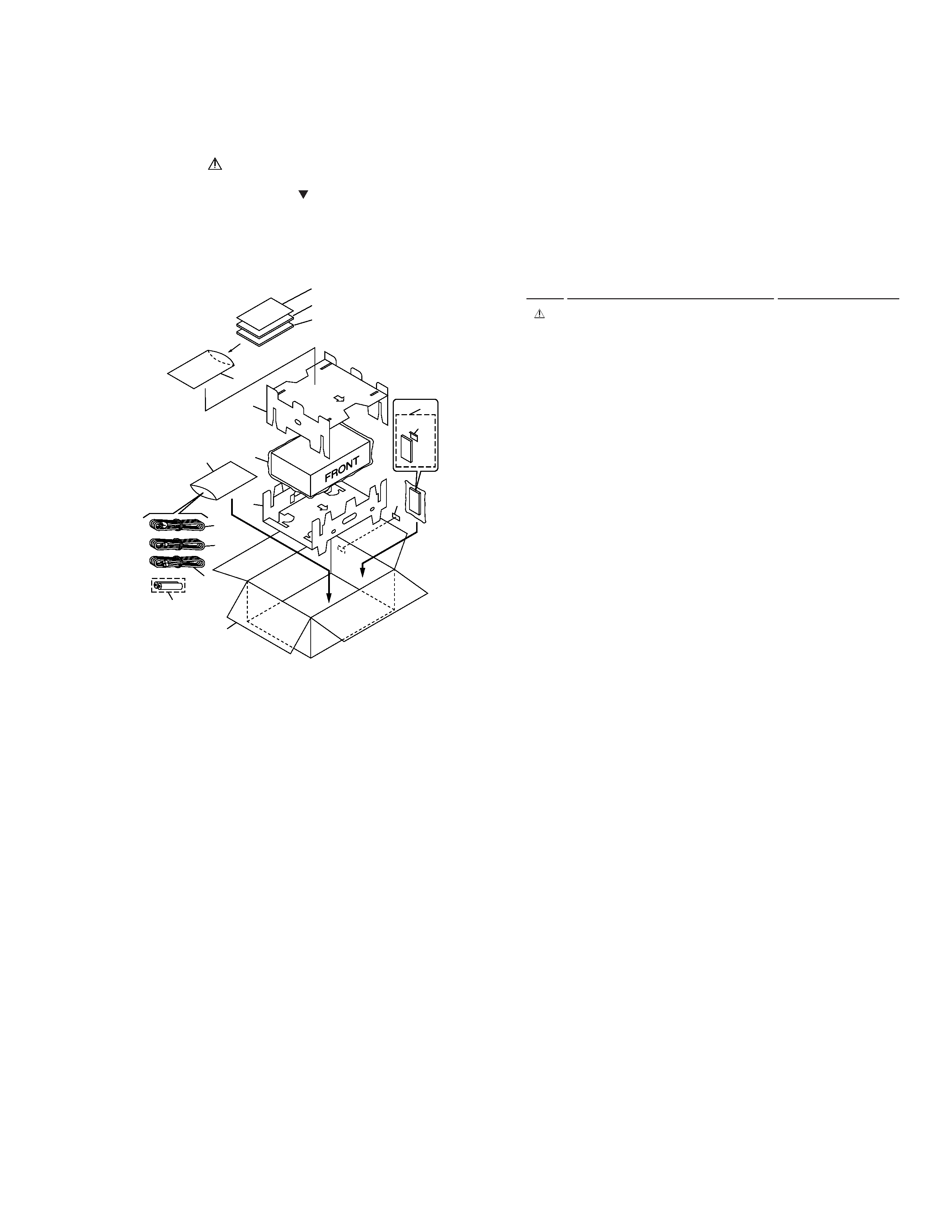
2.1 PACKING
1
Power Cord
PIADG1154
2
Operating Instructions
PIVRE1075
(English/French/German/Italian))
3
Caution
PIVRR1037
4
Audio Cord (L=1.5m)
PIVDE1033
5
Video Cord (L=1.5m)
PIVDE1048
NSP
6
Dry Cell Battery (R6P, AA)
PIVEM-013
7
Operating Instructions
PIVRF1046
(Spanish/Portguese/Dutch/Swedish)
8
Remote Control Unit
PIVXX2595
9
Polyethylene Bag
PIVHL1046
10
Battery Cover
PIVNK3703
11
Protector A
PIVHB1060
12
Protector B
PIVHB1061
13
Packing Case
PIVHG1765
14
Mirror Mat Sheet
PIZ23-007
15
Serial Number Label
PIRRW-168
(1) PACKING PARTS LIST
Mark No.
Description
Part No.
2. EXPLODED VIEWS AND PARTS LIST
NOTES:
· Parts marked by "NSP" are generally unavailable because they are not in our Master Spare Parts List.
· The mark found on some component parts indicates the importance of the safety factor of the part.
Therefore, when replacing, be sure to use parts of identical designation.
· Screws adjacent to mark on the product are used for disassembly.
9
7
2
3
11
14
9
12
10
15
8
1
4
5
13
6
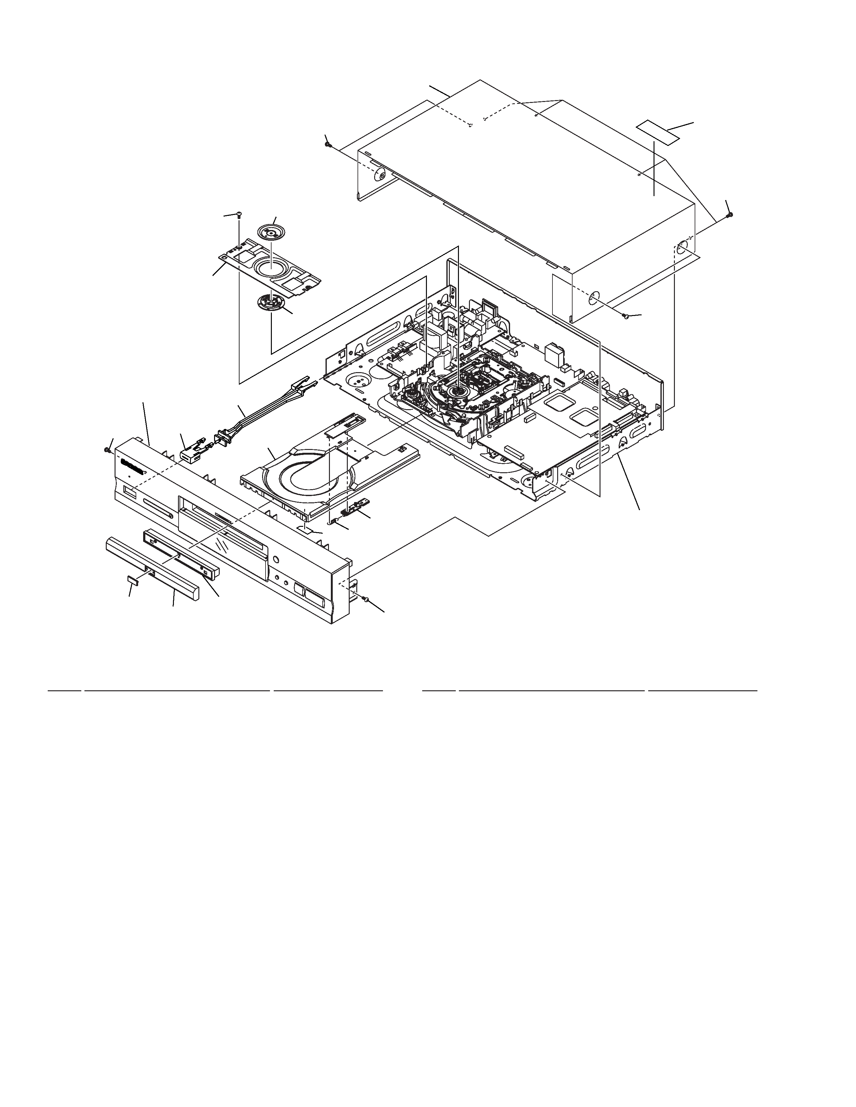
4
1
Bonnet Case S
PIVXX2539
2
DVD Plate
PIVAM1075
3
Tray Panel Plate
PIVNK4372
4
Tray Panel
PIVNK4158
5
Tray
PIVNL1731
6
· · · · ·
7
· · · · ·
8
Bridge
PIVNE2069
9
Clamper Plate
PIVNE2068
10
Clamper
PIVNL1738
11
Tray Stopper Spring
PIVBH1277
(1) EXTERIOR SECTION PARTS LIST
Mark No.
Description
Part No.
12
Tray Stopper
PIVNL1739
13
Tray Label
PIVRW1628
14
Screw
PIBPZ26P080FZK
15
Screw
PIIBZ30P080FMC
16
Screw
PIBCZ40P060FNI
17
Screw
PIBBZ30P080FMC
18
Caution Label
PIVRW1697
19
Power Button Joint
PIVNK4179
20
Power Button
PIVNK4374
Mark No.
Description
Part No.
16
18
1
14
9
8
10
17
16
19
20
15
2
3
4
Refer to
"2.3 FRONT PANEL
SECTION"
15
5
13
11
12
Refer to
"2.4 BOTTOM VIEW SECTION"
2.2 EXTERIOR SECTION