SPECIFICATIONS AND PARTS ARE SUBJECT TO CHANGE FOR IMPROVEMENT.
Multimedia LCD Projector
April 2001 Digital Media Group
Be sure to read this manual before servicing. To assure safety from fire, electric shock, injury, harmful
radiation and materials, various measures are provided in this Multimedia LCD Projector. Be sure to read
cautionary items described in the manual to maintain safety before servicing.
Caution
1. When replacing the lamp, avoid burns to your fingers, the lamp becomes very hot.
2. Never touch the lamp bulb with a finger or anything else. Never drop it or give it a shock. They may cause
bursting of the bulb.
3. This projector is provided with a high voltage circuit for the lamp. Do not touch the electric parts of power
unit (main), when turning on the projector.
4. Do not touch the exhaust fan, during operation.
5. The LCD module assembly is likely to be damaged. If replacing the LCD module assembly, do not hold
the FPC of the LCD module assembly.
Service Warning
1. Features --------------------------------------------------- 2
2. Specifications--------------------------------------------- 2
3. Names of each part ------------------------------------- 3
4. Adjustment ------------------------------------------------ 7
5. Troubleshooting ---------------------------------------- 13
6. Service points ------------------------------------------ 19
7. Block diagram ------------------------------------------ 22
8. Wiring diagram ----------------------------------------- 23
9. Basic circuit diagram---------------------------------- 27
10.Connector connection diagram -------------------- 75
11.Disassembly diagram--------------------------------- 77
12.Replacement parts list ------------------------------- 79
13.RS-232C communication ---------------------------- 80
Contents
SM0509
CPX980W
PJ1065
SERVICE MANUAL
CPX985W
2
1. Features
High brightness, High resolution
Compact size, light weight for portability
RGB output terminal
RS-232C Communication
Mouse emulation
Power zoom and power focus functions
Complies with VESA DDC1/2B specifications
Auto-adjustment function
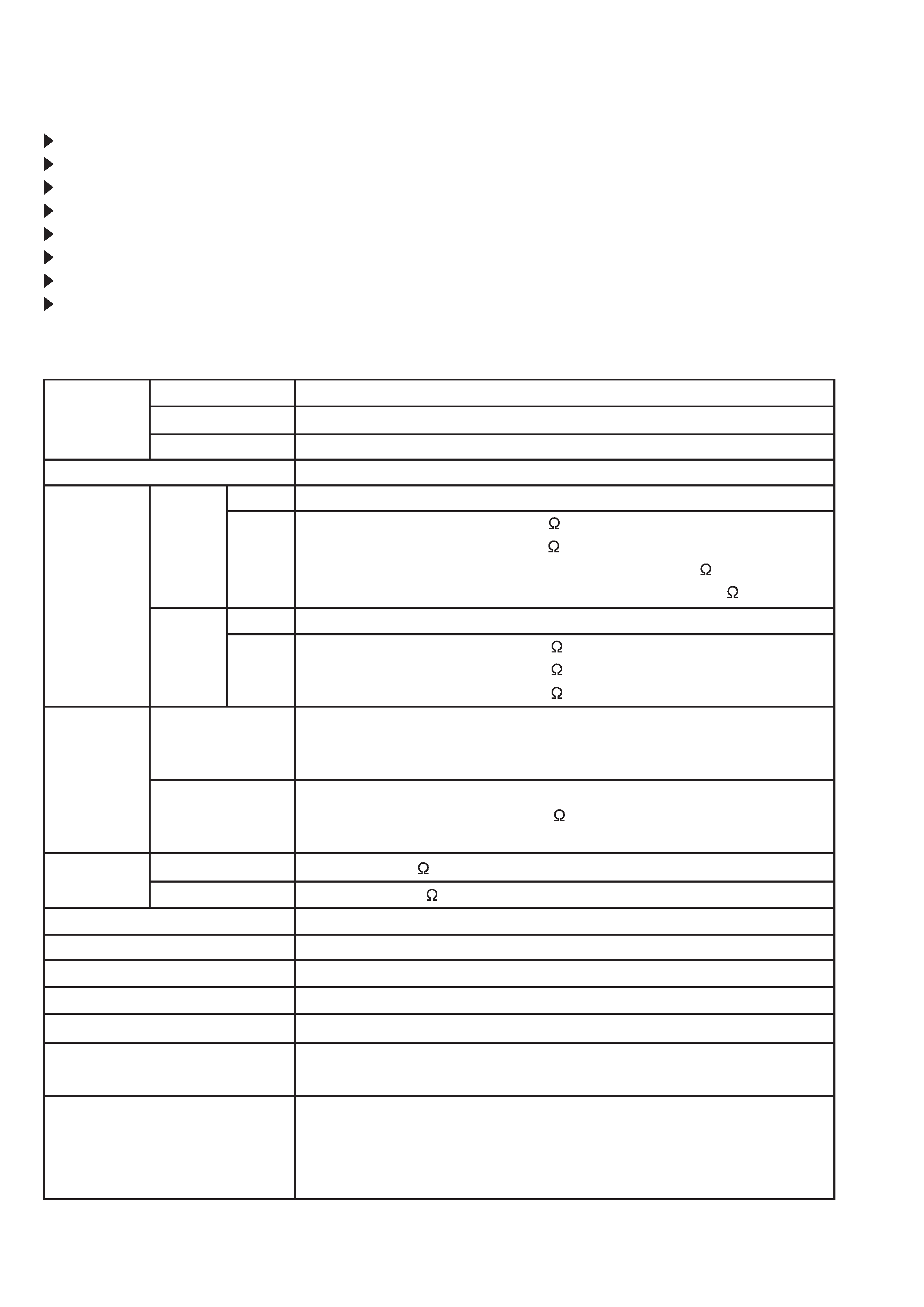
2. Specifications
Liquid crystal
panel
Lamp
Video input
Drive system
Panel size
Number of pixels
System
Level
System
Level
RGB
Audio
Speaker output
Power supply
Power consumption
Dimensions
Weight
Temperature range
Accessories
Digital input
Input
Output
Analog
input/output
TFT active matrix
1.3 inches
1024 (H) × 768 (V)
250W UHB
Composite
Component
Y/C
NTSC, 4.43NTSC, PAL, M-PAL, SECAM (N-PAL : only compulsion mode)
480i, 480p, 575i, 720p, 1035i, 1080i
Y
1.0Vp-p (75
termination)
Cb/Cr
0.7Vp-p (75
termination)
Pb/Pr
1.0Vp-p (75
termination)
Type
T.M.D.S
Video signal
DC:150~1200mV, AC:1.56Vp-p
Sync signal
TTL level
Type
R.G.B separate
Video signal
0.7Vp-p (75
termination)
Sync signal
H/V separate or composite, TTL level
200mVrms, 20k
or less
0~200mVrms, 1k
1.2W + 1.2W (stereo)
AC100~120V/4.5A, AC220~240V/2.2A
400W
289 (W) × 124 (H) × 350 (D) mm
6.4kg (14lbs)
Operation
: 0~35°C
Storage
: -20~60°C
Remote control transmitter × 1
RGB cable × 1
Video/Audio cable × 1
Mouse cable × 1
Component cable × 1
Composite
Y/C
1.0Vp-p (75
termination)
0.3Vp-p (PAL/SECAM burst signal, 75
termination)
Y : 1.0Vp-p (75
termination)
C : 0.286Vp-p (NTSC burst signal, 75
termination)
POWER cord × 3
BATTERIES LR6 × 2
Carrying case × 1
Quick start guide × 1
CD-ROM(User's guide) × 1
3
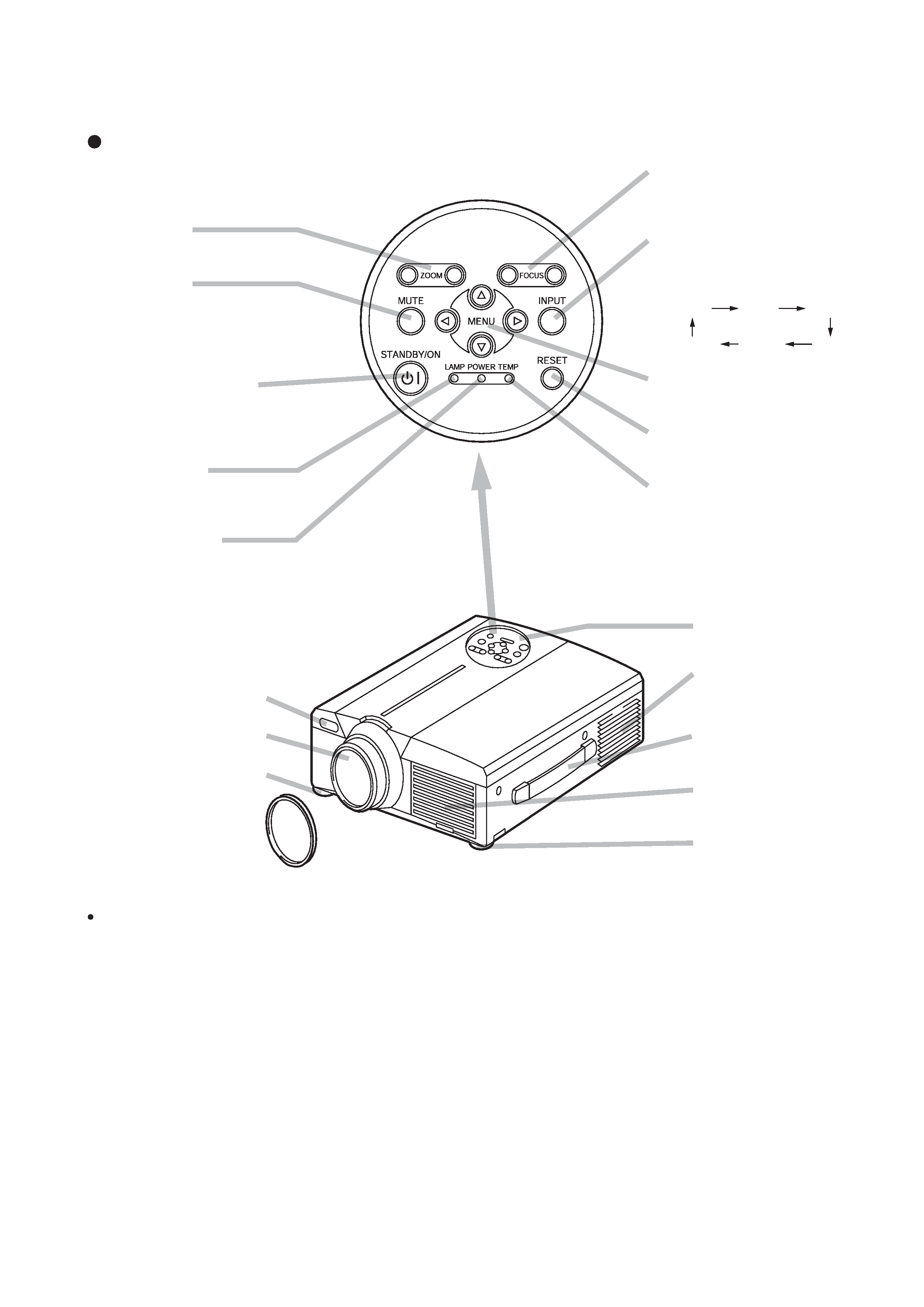
3. Names of each part
Parts names
ZOOM Button
Used to adjust the size of the image.
MUTE Button
This button turns the sound on and
off. Press once to turn the sound off;
then press again to turn the sound
back on.
STANDBY / ON Button
Press this button to turn the power on
and off. When turned off, the
projector enters standby status.
LAMP Indicator
This lamp lights or blinks when the
lamp is off.
POWER Indicator
This indicator lights or blinks during
standby and during operation.
FOCUS Button
Used to adjust the focus of the image on
the screen.
INPUT Button
Press this button to switch the input. The
input changes in the following sequence
each time this button is pressed.
MENU Button
Displays the image menu.
RESET Button
Used to reset the initial settings.
TEMP Indicator
This indicator lights or blinks when the
internal temperature of the projector
rises and when the fan malfunctions.
RGB1
RGB2
DIGITAL
COMPONENT
S-VIDEO
VIDEO
Remote Control Sensor
Lens
Foot Adjuster
Lens Cap
Control Panel
Ventilation Openings
(exhaust)
Carrying Handle
Air Filter and Intake
for the Cooling Fan
Foot Adjuster
Control Panel
Front/Right View
Use the remote control transmitter in front of the remote control sensor at a
distance of about 5 m or less and an angle of 30 degrees to the left or right
of the center.
4
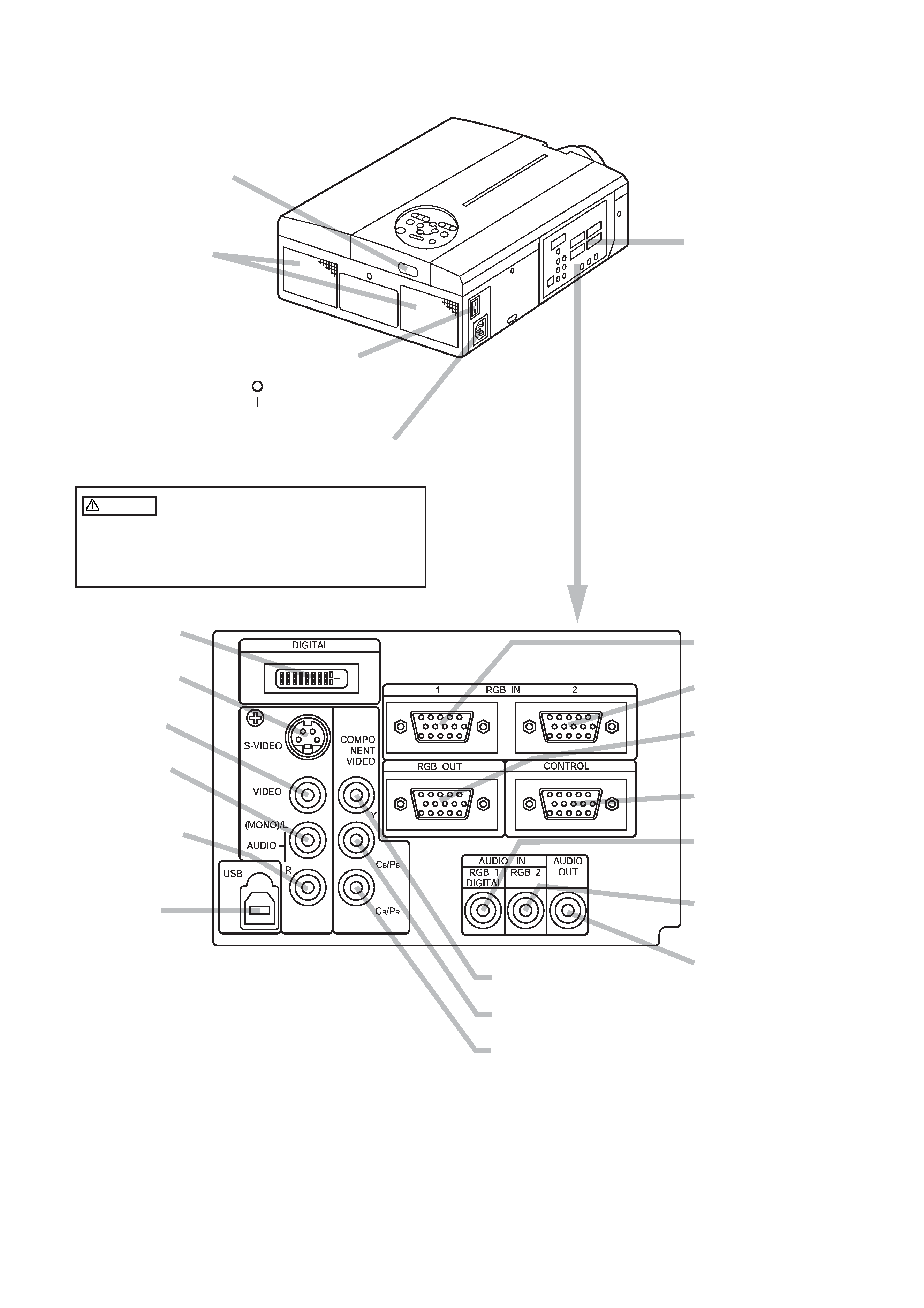
Remote Control Sensor
AC Inlet
Used to connect the accessory power cord.
Speaker
Power Switch
Used to turn the power on and off.
: OFF
: ON
Terminal Panel
(Refer below)
Rear/Left View
DIGITAL Terminal
Digital video receptacle
S-VIDEO Terminal
Mini DIN 4-pin connector
VIDEO Terminal
RCA jack
AUDIO(MONO)/L
Terminal
RCA jack
AUDIO R Terminal
RCA jack
USB Terminal
The mouse cursor can be
controlled by remote control
by connecting to a personal
computer.
RGB IN 1 Terminal
D-sub 15-pin shrink
RGB IN 2 Terminal
D-sub 15-pin shrink
RGB OUT Terminal
D-sub 15-pin shrink
CONTROL Terminal
D-sub 15-pin shrink
AUDIO IN RGB1
Terminal
Stereo mini-pin jack
AUDIO IN RGB2
Terminal
Stereo mini-pin jack
AUDIO OUT
Terminal
Stereo mini-pin jack
COMPONENT VIDEO
Y Terminal
RCA jack
CB/PB Terminal
RCA jack
CR/PR Terminal
RCA jack
Terminal Panel
Caution Connecting to the AC Inlet
Make sure the accessory power cord is plugged
into the AC Inlet as far as it will go. Incomplete
connection can result in fire or electrical shock.
5
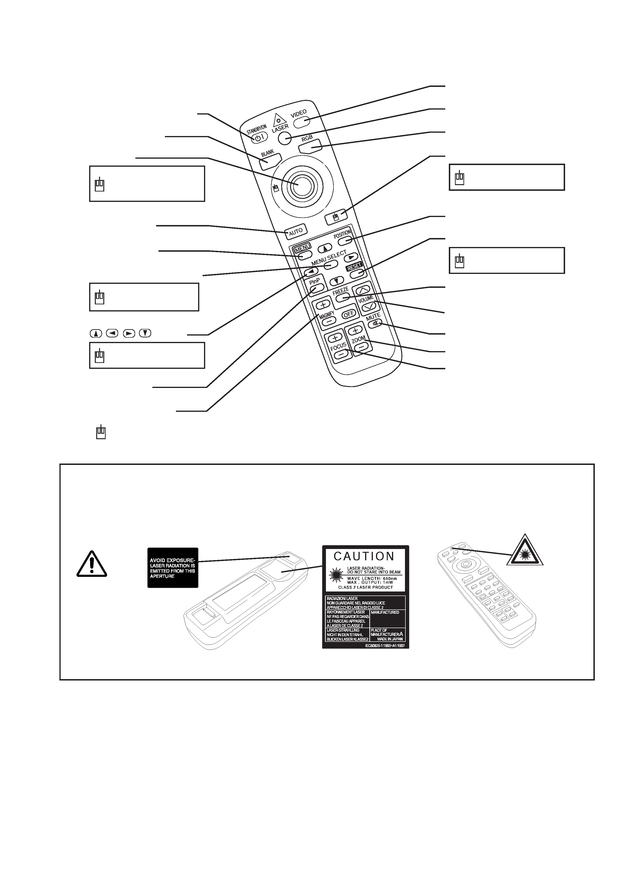
WARNING
The laser pointer of the remote control transmitter is used in place of a finger or rod. Never look
directly into the laser beam outlet or point the laser beam at other people. The laser beam can
cause vision problems.
STANDBY/ON Button
BLANK Button
Disk Pad
AUTO Button
MENU Button
MENU SELECT Button
,
,
,
Button
MAGNIFY Button
Used to operate the
mouse shift function
and left click function.
Used to click the
left mouse button.
Used to operate the
mouse shift function.
VIDEO Button
LASER Button
RGB Button
MOUSE / RIGHT Button
POSITION Button
RESET Button
FREEZE Button
VOLUME Button
MUTE Button
ZOOM Button
Used to click the
right mouse button.
Used to click the
right mouse button.
REMOTE CONTROL TRANSMITTER
NOTE: To prevent any malfunction;
· Do not give the Remote control transmitter any physical impact. Take care not to drop.
· Do not place the heavy objects on the Remote control transmitter.
· Do not wet the Remote control transmitter or place it on any wet object.
· Do not place the Remote control transmitter close to the cooling fan of the projector.
· Do not disassemble the Remote control transmitter in case of malfunction. Please bring it to the service station.
: These functions works when the mouse control function is activated. Remember, the POSITION,
BLANK ON and MENU ON functions disable the mouse control function.
PinP Button
FOCUS Button