CPX430W
(C7X)
SPECIFICATIONS AND PARTS ARE SUBJECT TO CHANGE FOR IMPROVEMENT.
Multimedia LCD Projector
February 2002 Digital Media Systems Division
SERVICE MANUAL
Be sure to read this manual before servicing. To assure safety from fire, electric shock, injury, harmful
radiation and materials, various measures are provided in this HITACHI Multimedia LCD Projector. Be sure to
read cautionary items described in the manual to maintain safety before servicing.
Caution
1. When replace the lamp, to avoid burns to your fingers. The lamp becomes too hot.
2. Never touch the lamp bulb with a finger or anything else. Never drop it or give it a shock. They may cause
bursting of the bulb.
3. This projector is provided with a high voltage circuit for the lamp. Do not touch the electric parts of power
unit (main), when turn on the projector.
4. Do not touch the exhaust fan, during operation.
5. The LCD module assembly is likely to be damaged. If replacing to the LCD module assembly, do not hold
the FPC of the LCD module assembly.
6. Use the cables which are included with the projector or specified.
Service Warning
1. Features --------------------------------------------------- 2
2. Specifications--------------------------------------------- 2
3. Names of each part ------------------------------------- 3
4. Adjustment ------------------------------------------------ 5
5. Troubleshooting ---------------------------------------- 11
6. Service points ------------------------------------------ 16
7. Block diagram ------------------------------------------ 23
8. Connector connection diagram -------------------- 24
9. Wiring diagram ----------------------------------------- 25
10.Schematic diagrams ---------------------------------- 30
11.Disassembly diagram--------------------------------- 63
12.Replacement parts list ------------------------------- 65
13.RS-232C communication ---------------------------- 66
Contents
SM0520

ENGLISH
SAFETY PRECAUTIONS
WARNING: The following precautions must be observed.
ALL PRODUCTS
Before any service is performed on the chassis an
isolation transformer should be inserted between the
power line and the product.
1. When replacing the chassis in the cabinet, ensure
all the protective devices are put back in place.
2. When service is required, observe the original
lead dressing. Extra precaution should be taken to
ensure correct lead dressing in any high voltage
circuitry area.
3. Many electrical
and
mechanical parts in
HITACHI products have special safety related
characteristics. These characteristics are often not
evident from visual inspection, nor can the
protection afforded by them necessarily be
obtained by using replacement components rated
for higher voltage, wattage, etc. Replacement
parts
which
have
these
special
safety
characteristics are identified by marking with a
! on the schematics and the replacement parts
list.
The use of a substitute replacement component
that does not have the same safety characteristics
as the HITACHI recommended replacement one,
shown in the parts list, may create electrical
shock, fire, X-radiation, or other hazards.
4. Always replace original spacers and maintain lead
lengths. Furthermore, where a short circuit has
occurred, replace those components that indicate
evidence of overheating.
5. Insulation resistance should not be less than 2M
ohms at 500V DC between the main poles and
any accessible metal parts.
6. No flashover or breakdown should occur during
the dielectric strength test, applying 3kV AC or
4.25kV DC for two seconds between the main
poles and accessible metal parts.
7. Before returning a serviced product to the
customer, the service technician must thoroughly
test the unit to be certain that it is completely safe
to operate without danger of electrical shock. The
service technician must make sure that no
protective device built into the instrument by the
manufacturer
has
become
defective,
or
inadvertently damaged during servicing.
CE MARK
1. HITACHI products may contain the CE mark on
the rating plate indicating that the product
contains parts that have been specifically
approved
to
provide
electromagnetic
compatibility to designated levels.
2. When replacing any part in this product, please
use only the correct part itemised in the parts list
to ensure this standard is maintained, and take
care to replace lead dressing to its original state,
as this can have a bearing on the electromagnetic
radiation/immunity.
PICTURE TUBE
1. The line output stage can develop voltages in
excess of 25kV; if the E.H.T. cap is required to be
removed, discharge the anode to chassis via a
high value resistor, prior to its removal from the
picture tube.
2. High voltage should always be kept at the rated
value of the chassis and no higher. Operating at
higher voltages may cause a failure of the picture
tube or high voltage supply, and also, under
certain circumstances could produce X-radiation
levels moderately in excess of design levels. The
high voltage must not, under any circumstances,
exceed 29kV on the chassis (except for projection
Televisions).
3. The primary source of X-radiation in the product
is the picture tube. The picture tube utilised for
the above mentioned function in this chassis is
specially constructed to limit X-radiation. For
continued X-radiation protection, replace tube
with the same type as the original HITACHI
approved type
4. Keep the picture tube away from the body while
handling. Do not install, remove, or handle the
picture tube in any manner unless shatterproof
goggles are worn. People not so equipped should
be kept away while picture tubes are handled
LASERS
If the product contains a laser avoid direct exposure to
the beam when the cover is open or when interlocks are
defeated or have failed.
2
CP-X430W
1. Features
High brightness, High resolution
Compact size, light weight for portability
RS-232C Communication
Auto-adjustment function
Liquid crystal
panel
Lamp
RGB
signal
input
Video
signal
input
Signal
output
Drive system
Panel size
Number of pixels
RGB IN
Digital input
Signal
System
System
AUDIO IN
AUDIO IN
VIDEO IN
RGB OUT
AUDIO OUT
S-VIDEO IN
COMPONENT
VIDEO
Audio input
Speaker output
Power supply
Power consumption
Dimensions
Weight
Temperature range
Accessories
TFT active matrix
0.9 inches
1024 (H) × 768 (V)
250W UHB
Video: Analog 0.7Vp-p, 75
terminator
H/V. sync.: TTL level (positive/negative)
Composite sync.: TTL level
D-sub 15-pin shrink jack
Type: T.M.D.S
Amplitude differential signal: DC: 150~1200mV
AC: 1.56Vp-p
Amplitude signal: TTL level ("L" : less than 0.8V, "H" : more than 2.0V)
Video: Analog 0.7Vp-p, 75
output impedance (positive)
H/V. sync.: TTL level (positive/negative)
Composite sync.: TTL level
D-sub 15-pin shrink jack
Brightness signal: 1.0Vp-p, 75
terminator
Color signal: 0.286Vp-p (NTSC, burst signal), 75
terminator
0.3Vp-p (PAL/SECAM, burst signal), 75
terminator
Mini DIN 4-pin jack
200mVrms, 47k
(max. 3.0Vp-p)
Stereo mini jack
NTSC, NTSC4.43, PAL (BGDHI), SECAM, PAL-M, PAL-N, PAL60
200mVrms, 50k
(max. 3.0Vp-p)
RCA jack
1.0Vp-p, 75
terminator
RCA jack
1.0Vp-p, 75
terminator (positive)
0.7Vp-p, 75
terminator (positive)
0.7Vp-p, 75
terminator (positive)
200mVrms, 47k
1W +1W (stereo)
AC100~120V/4.5A, AC220~240V/1.9A
410W
360 (W) × 112.5 (H) × 266 (D) mm
4.5kg (9.92lbs)
Operation
: 0~35°C
Storage
: -20~60°C
Remote control transmitter × 1
RGB cable × 1
Component cable × 1
Mouse cable (PS/2) × 1
POWER cord × 3
200mVrms, output impedance 1k
(max. 3.0Vp-p)
Stereo mini jack
Battery × 2
Carrying bag × 1
Lens cap (set wearing) × 1
User's manual (with Safety Instructions)× 1
1
2
1
2
Y
L
R
CB/CR
PB/PR
480i, 480p, 575i, 720p, 1080i
2. Specifications
Vertical / Horizontal keystone function
P. in P. function
My screen function (User start up screen)
3
CP-X430W
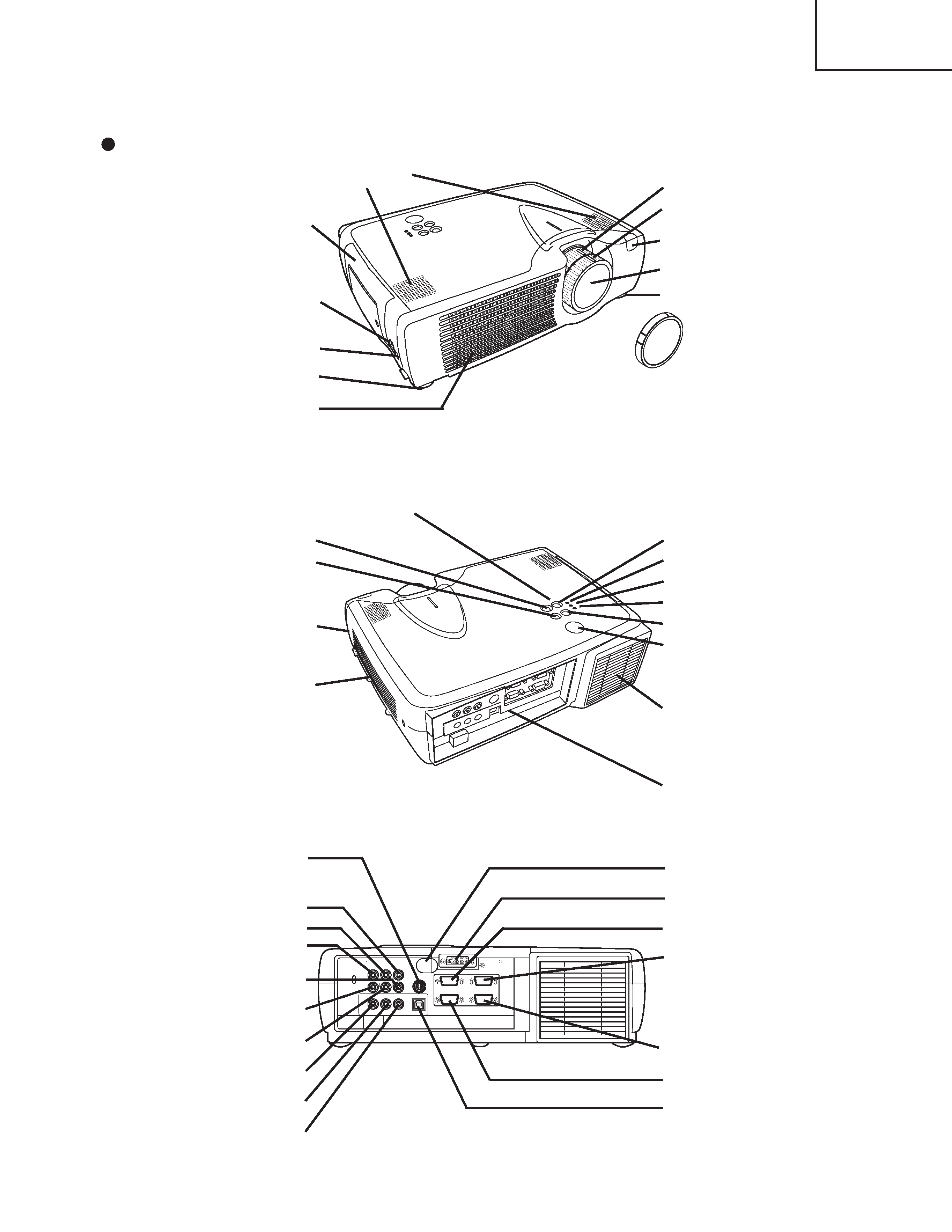
3. Names of each part
Parts names
Control Panel
AC Inlet
(to the Power Cord)
Power Switch
Foot Adjuster
Ventilation Openings
(Intake)
Zoom Knob
Focus Ring
Remote Control Sensor
Lens
Foot Adjuster
FRONT/LEFT VIEW OF
THE PROJECTOR
Speaker
Carrying Handle
STANDBY/ON Button
KEYSTONE Button
Foot Adjuster Button
Filter Cover
Air Filter and Intake
for the Cooling Fan
INPUT Button
LAMP Indicator
TEMP Indicator
POWER Indicator
RESET Button
MENU Button
Ventilation Openings
(exhaust)
REAR/RIGHT VIEW OF
THE PROJECTOR
Terminal Panel
(Refer below)
TERMINAL PANEL
S-VIDEO Terminal
COMPONENT VIDEO
Y Terminal
CB/PB Terminal
CR/PR Terminal
VIDEO IN Terminal
AUDIO IN R Terminal
AUDIO IN L Terminal
AUDIO IN 1 Terminal
AUDIO IN 2 Terminal
AUDIO OUT Terminal
Remote Control Sensor
DVI Terminal
RGB IN 1 Terminal
RGB IN 2 Terminal
CONTROL Terminal
RGB OUT Terminal
USB Terminal
(
)
Lens Cap
4
CP-X430W
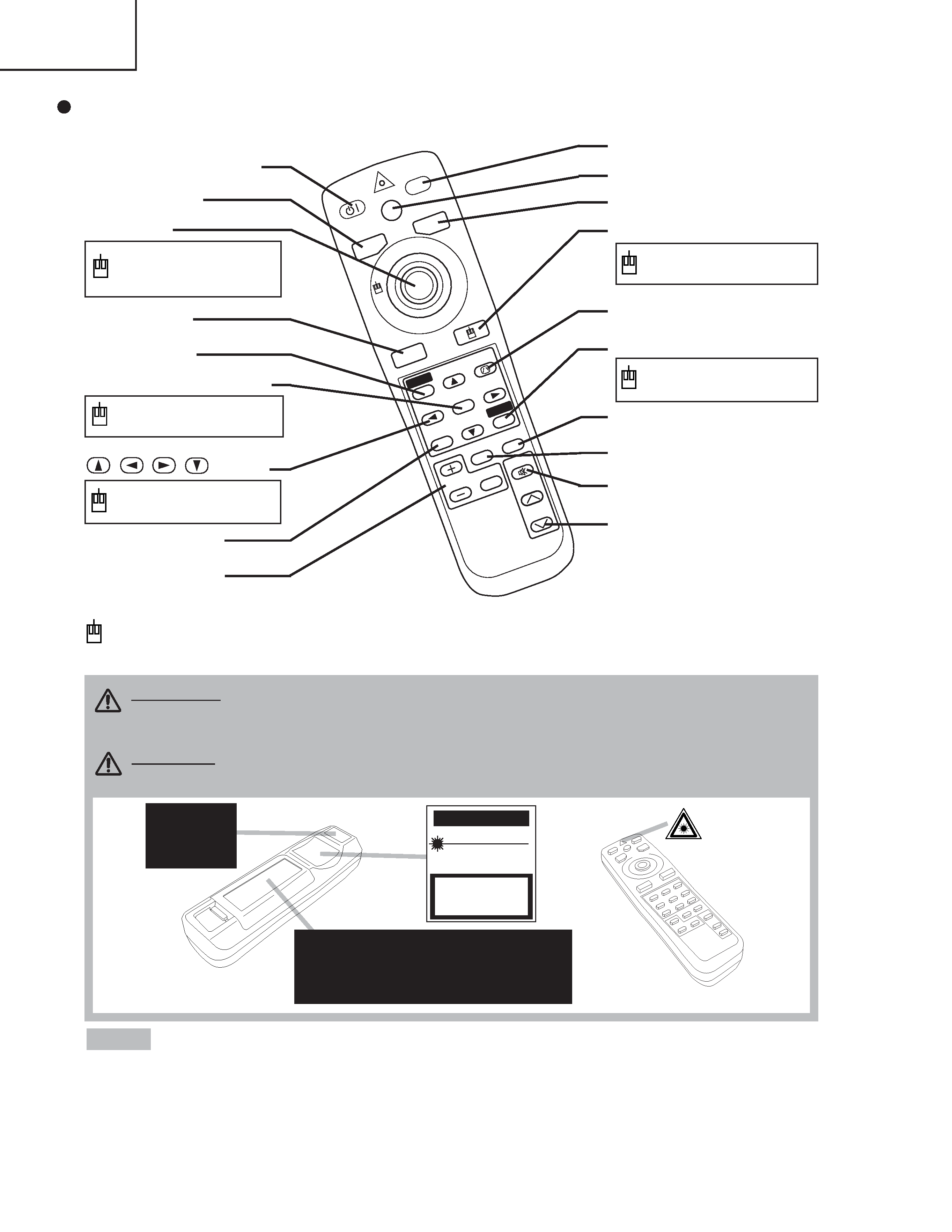
Remote control transmitter
STAN
DBY/O
N
LASER
BLANK
RGB
VIDEO
AUT
O
MENU
MENU
SELE
CT
KEYST
ONE
RESET
FREE
ZE
PinP
MAGNIFY
POSITION
OFF
VOLUME
MUTE
REMOTE CONTROL
TRANSMITTER
· Keep the remote control transmitter away from children and pets.
· Do not give the remote control transmitter any physical impact. Take care not to drop.
· Do not place the heavy objects on the remote control transmitter.
· Do not wet the remote control transmitter or place it on any wet object.
· Do not place the remote control transmitter close to the cooling fan of the projector.
· Do not disassemble the remote control transmitter.
NOTE
STANDBY/ON Button
LASER Button
VIDEO Button
Disk Pad
Used to operate the
mouse shift function and
left click function.
AUTO Button
MENU Button
MENU SELECT Button
Used to click the left
mouse button.
,
,
,
Button
Used to operate the
mouse shift function.
MAGNIFY Button
BLANK Button
RGB Button
MOUSE / RIGHT Button
Used to click the right
mouse button.
RESET Button
Used to click the right
mouse button.
FREEZE Button
MUTE Button
PinP Button
KEYSTONE Button
VOLUME Button
These functions works when the mouse control function is activated. Remember, the POSITION,
BLANK ON and MENU ON functions disable the mouse control function.
WARNING · The laser pointer of the remote control transmitter is used in
place of a finger or rod. Never look directly into the laser beam outlet or point
the laser beam at other people. The laser beam can cause vision problems.
CAUTION · Use of controls or adjustments or performance of procedures
other than those specified herein may result in hazardous radiation exposure.
POSITION Button
Complies with 21 CFR 1040. 10 and 1040. 11 except for deviations
pursuant to Laser Notice No.50, dated 2001.7.26
SMK CORPORATION
6-5-5 Togoshi Shinagawa-ku, Tokyo, JAPAN 142-8511
MANUFACTURED Novemver 2001
PLACE OF MANUFACTURER: A
CA UTION
LASER RADIATION-
DO NOT STARE INTO BEAM
MAX. OUTPUT: 1mW
WAVE LENGTH: 650nm
CLASS2 LASER PRODUCT
LASER RADIATION
IEC60825-1 : 1993+A1:1997
MAX. OUTPUT: 1mW
WAVE LENGTH: 650nm
DO NOT STARE INTO BEAM
CLASS2 LASER PRODUCT
AVOID EXPOSURE-
LASER RADIATIONS IS
EMITTED FROM THIS
APERTURE