SM
0518
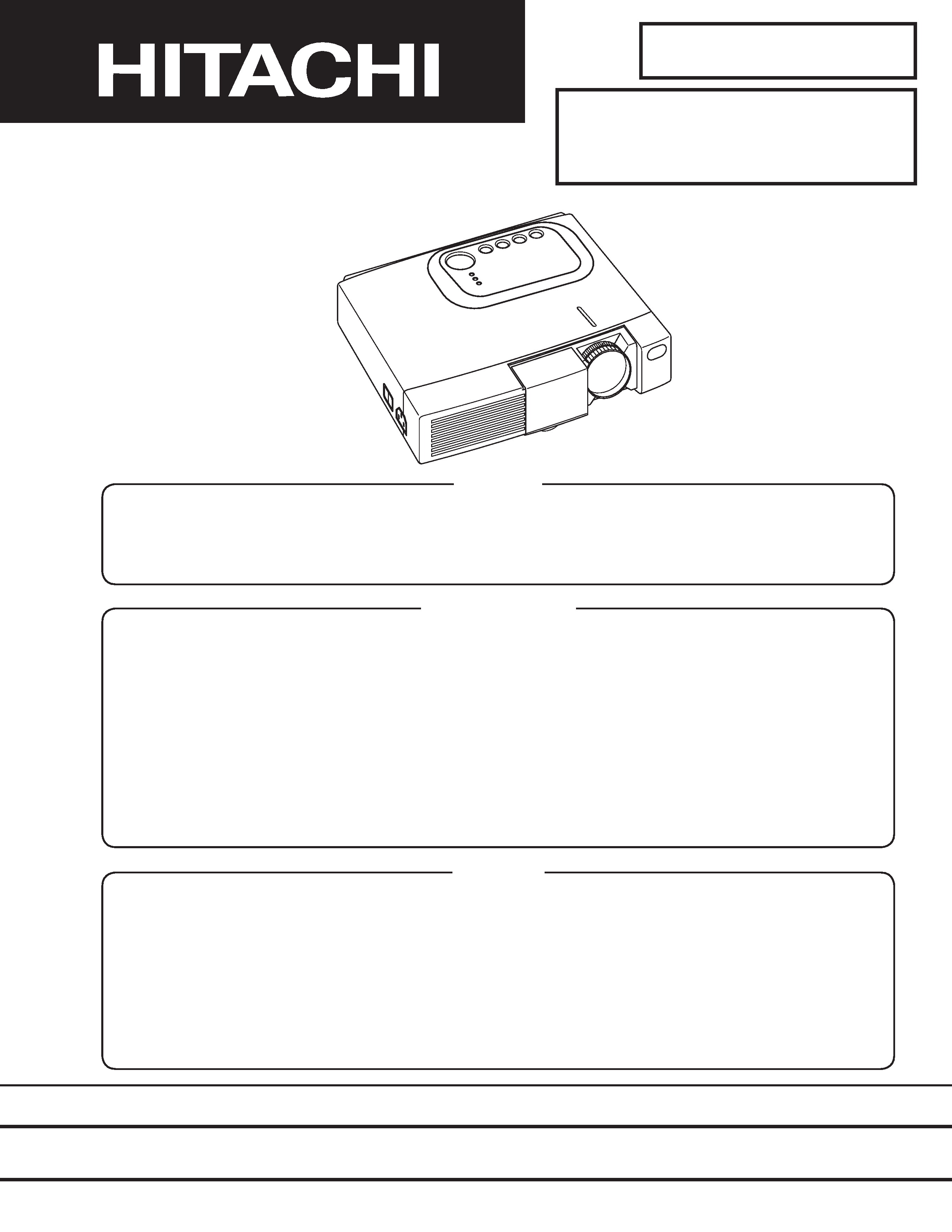
CPX275W (C3XM2)
SPECIFICATIONS AND PARTS ARE SUBJECT TO CHANGE FOR IMPROVEMENT.
Multimedia LCD Projector
December 2001 Digital Media Group
SERVICE MANUAL
Be sure to read this manual before servicing. To assure safety from fire, electric shock, injury, harmful
radiation and materials, various measures are provided in this Hitachi Multimedia LCD Projector. Be sure to
read cautionary items described in the manual to maintain safety before servicing.
Caution
1. When replacing the lamp, avoid burns to your fingers. The lamp becomes very hot.
2. Never touch the lamp bulb with a finger or anything else. Never drop it or give it a shock. They may cause
bursting of the bulb.
3. This projector is provided with a high voltage circuit for the lamp. Do not touch the electric parts of power
unit (main), when turn on the projector.
4. Do not touch the exhaust fan, during operation.
5. The LCD module assembly is likely to be damaged. If replacing the LCD module assembly, do not hold
the FPC of the LCD module assembly.
6. Use the cables which are included with the projector or specified.
Service Warning
1. Features --------------------------------------------------- 2
2. Specifications--------------------------------------------- 2
3. Names of each part ------------------------------------- 3
4. Adjustment ------------------------------------------------ 5
5. Troubleshooting ---------------------------------------- 12
6. Service points ------------------------------------------ 17
7. Block diagram ------------------------------------------ 23
8. Connector connection diagram -------------------- 24
9. Wiring diagram ----------------------------------------- 25
10.Basic circuit diagram---------------------------------- 32
11.Disassembly diagram--------------------------------- 48
12.Replacement parts list ------------------------------- 50
13.Option parts list ---------------------------------------- 51
Contents
PJ550 (C3XM2)
14.RS-232C communication ---------------------------- 52
15.Command data chart --------------------------------- 54
2
1. Features
High brightness, High resolution
Compact size, light weight for portability
RS-232C Communication
Complies with VESA DDC1/2B specifications
Auto-adjustment function
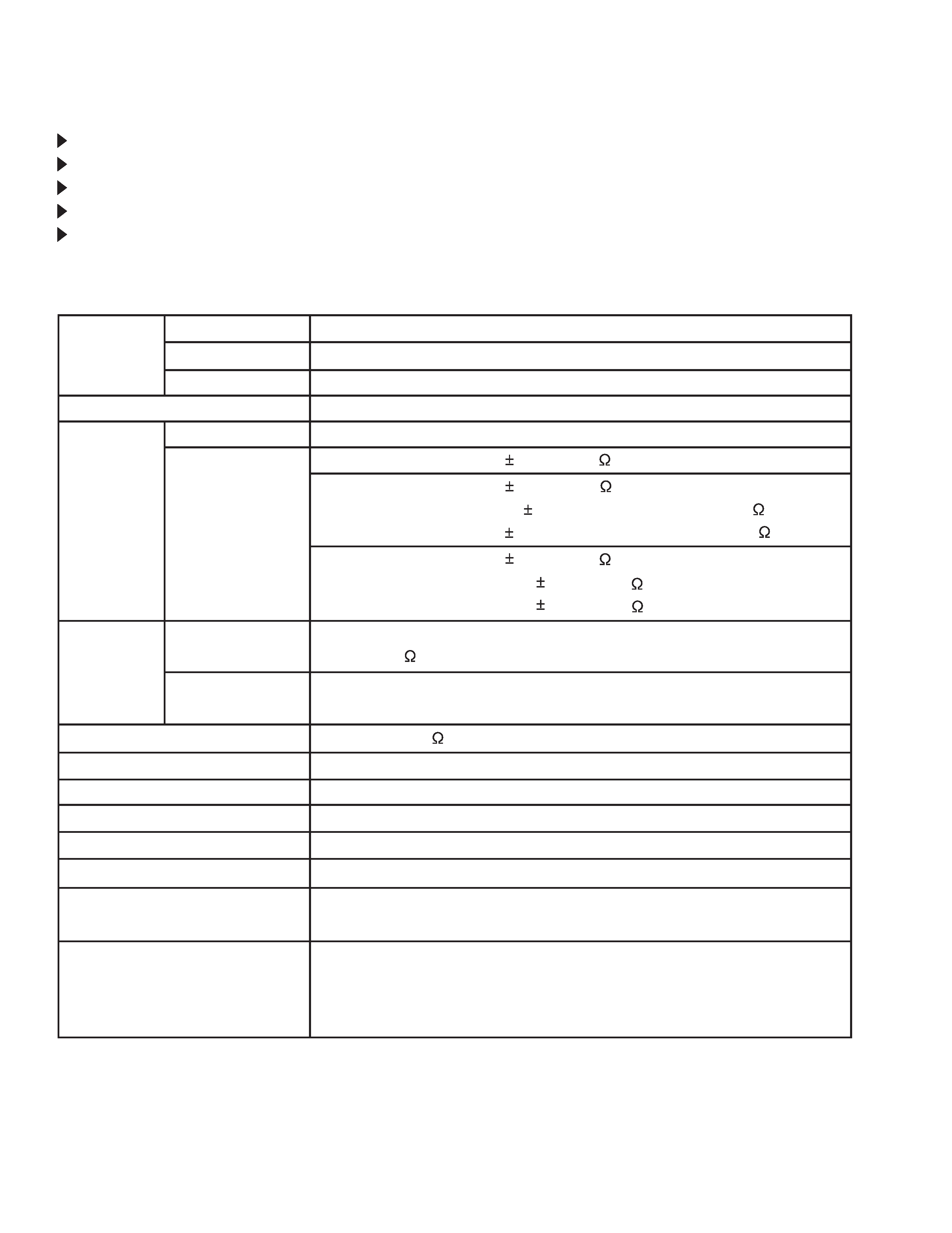
2. Specifications
Liquid crystal
panel
Lamp
Video input
RGB input
Drive system
Panel size
Number of pixels
System
Level
Video signal
Sync signal
Audio input
Speaker output
Power supply
Power consumption
Dimensions
Weight
Temperature range
Accessories
TFT active matrix
0.7 inches
1024 (H) × 768 (V)
150W UHB
Composite
Y/C
NTSC, 4.43NTSC, PAL, M-PAL, PAL60, N-PAL or SECAM
Analog RGB input
0.7Vp-p (75
termination)
H/V separate
TTL level
200mVrms, 47k
1.0W (mono)
AC100~120V/2.7A, AC220~240V/1.3A
240W
289 (W) × 84 (H) × 215 (D) mm
2.49kg (5.4lbs)
Operation
: 0~35°C
Storage
: -20~60°C
Remote
Control Transmitter x1
RGB
Cable x1
Component
Cable x1
P
ower Cord x3
1.0 0.1Vp-p (75
termination)
0.3 0.1Vp-p (PAL/SECAM burst signal, 75
termination)
Y : 1.0 0.1Vp-p (75
termination)
C : 0.286 0.1Vp-p (NTSC burst signal, 75
termination)
Battery (inside Remote control transmitter)
x1
Carrying
Bag x1
User's
Manual (with Safety Instructions) x1
Component
PB/PR : 0.7 0.1Vp-p (75
termination)
Y : 1.0 0.1Vp-p (75
termination)
CB/CR : 0.7 0.1Vp-p (75
termination)
3
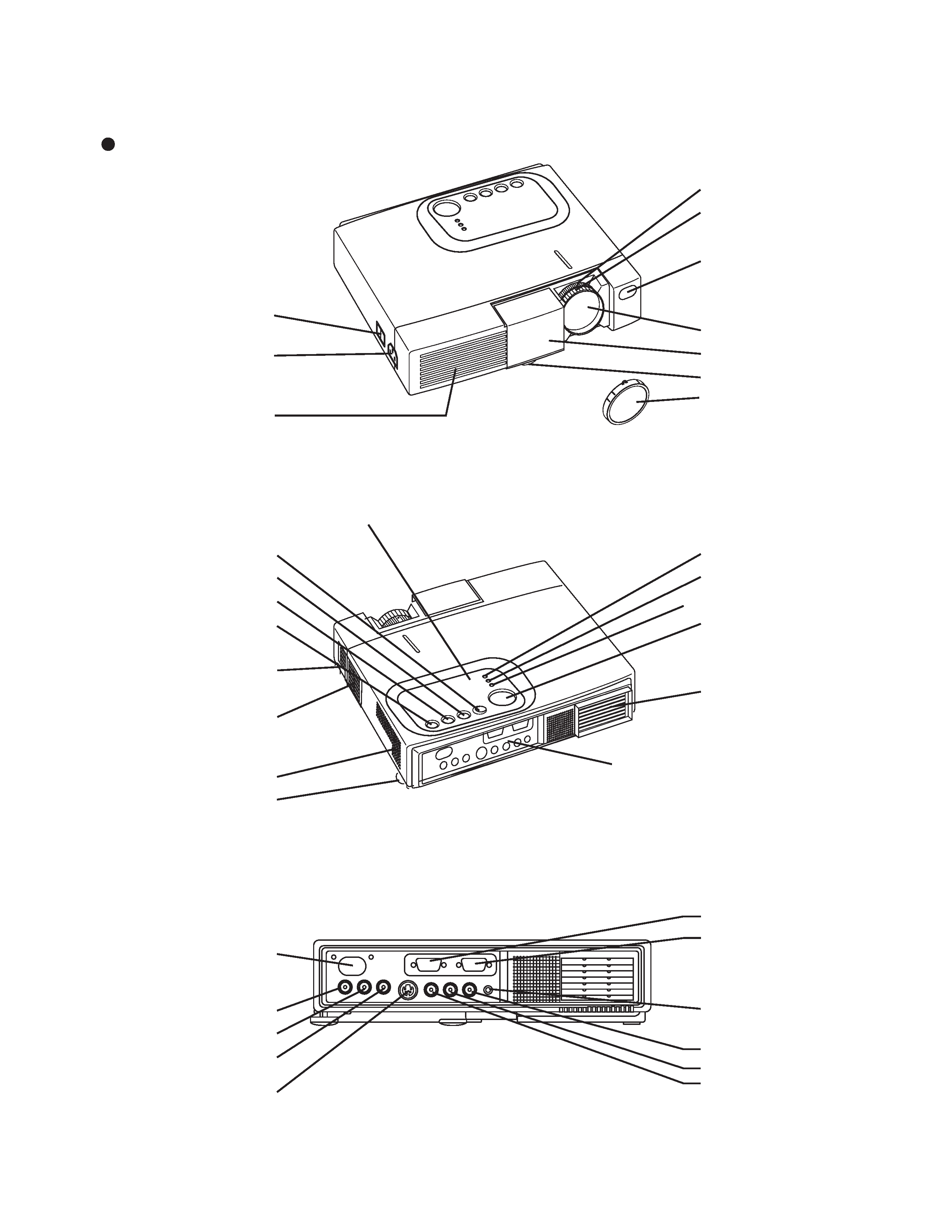
3. Names of each part
Parts names
Remote Control Sensor
COMPONENT
Y Terminal
CB/PB Terminal
CR/PR Terminal
S-VIDEO Terminal
RESET Button
KEYSTONE Button
INPUT Button
STANDBY/ON Button
Foot Adjuster Button
Air Filter and Intake
(for the Cooling Fan)
Speaker
Rear Foot Adjuster
LAMP Indicator
TEMP Indicator
POWER Indicator
MENU Button
Ventilation Openings
(Exhaust)
Terminal Panel (Refer below)
RGB Terminal
CONTROL Terminal
AUDIO Terminal
AUDIO
R Terminal
L Terminal
VIDEO Terminal
Power Switch
AC Inlet
(to the Power Cord)
Ventilation Openings
(Intake)
Zoom Knob
Focus Ring
Remote Control Sensor
Lens
Slide Lens door (CPX275W)
Foot Adjuster
Control Panel
FRONT / LEFT / VIEW
REAR / RIGHT / VIEW
TERMINAL PANEL
Lens Cap (PJ550)
4
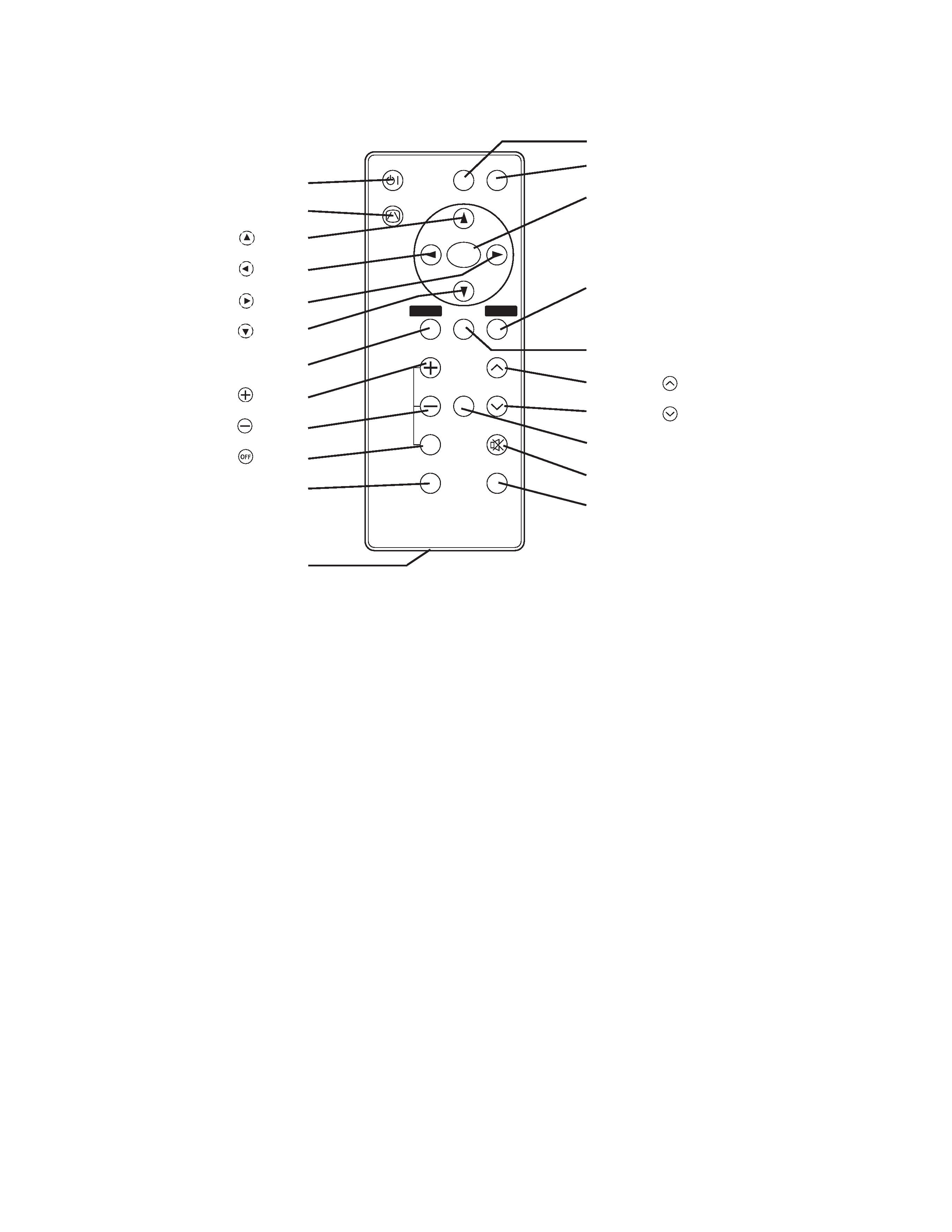
VIDEO
STANDBY/ON
KEYSTONE
POSITION
FREEZE
MAGNIFY
VOLUME
AUTO
OFF
BLANK
MENU
SELECT
RGB
MUTE
MENU
RESET
STANDBY/ON Button
KEYSTONE Button
Button
Button
Button
Button
MENU Button
MAGNIFY
Button
MAGNIFY
Button
MAGNIFY
Button
AUTO Button
Battery Holder
VIDEO Button
RGB Button
MENU SELECT Button
RESET Button
POSITION Button
VOLUME
Button
VOLUME
Button
FREEZE Button
MUTE Button
BLANK Button
REMOTE CONTROL TRANSMITTER

5
4. Adjustment
4-1 Before adjusting
1. Before starting adjustment, warm up the projector
for about 10 minutes.(Blank white)
2. Set Zoom Wide to Max. And project an image a
distance of more than 40 inches.
3. Normalizing the video adjustment.
(Press the [MENU] button of the Remote control
transmitter to display the Setup menu, and then press
the [RESET] button. And select the [DEFAULT].)
*note : The setup menu is not displayed on with no
signal.
4. Set the another [MENU] as follows.
a. GAMMA in the IMAGE menu is NORMAL.
b. COLOR TEMP. in the IMAGE menu is NORMAL.
c. WHISPER in the OPT menu is NORMAL.
5. Perform all adjustments from the Adjustment menu.
Perform the following operations to display the
Adjustment menu.
a. Press the [MENU] button of the Remote control
transmitter (the Setup menu will appear).
b. Next, press the [RESET] button one time. And
press the [RESET] button again for 5 seconds
or more (the Adjustment menu will appear).
4-2 Ghost adjustment
Signals for internal adjustment
30%
30%
112/255
bit
0/255
bit
Adjustment procedure
1. Use DAC-P - GHOST - R: in the Adjustment menu
to adjust so that R color ghost is at a minimum.
(Set the adjustment value to default, and then raise
the value. When a ghost appears to the left of a
vertical line, reduce the value by 2 steps.)
2. In the same way, use DAC-P - GHOST-G: in the
Adjustment menu to adjust so that G color ghost is
at a minimum.
3. In the same way, use DAC-P - GHOST-B: in the
Adjustment menu to adjust so that B color ghost is
at a minimum.
4-3 Flicker adjustment (V.COM adjustment)
Signals for internal adjustment
Adjustment procedure
1. Make this adjustment after completing the
adjustment in 4-2 Ghost adjustment.
2. Use DAC-P - V.COM - R: in the Adjustment menu
to adjust so that the flicker at the center of the
screen is less than the flicker at the periphery.
(When the flicker is about the same across the
whole screen, adjust so that the flicker at the
center of the screen is somewhat less than
elsewhere.)
3. In the same way, use DAC-P - V.COM-G: in the
Adjustment menu to adjust the G color flicker.
4. In the same way, use DAC-P - V.COM-B: in the
Adjustment menu to adjust the B color flicker.