OPERATING GUIDE FOR COLOUR
MONITOR
CPX14QE
UK
Contents (English)
Safety
3
Mains Supply
Important note for the U.K.
Plug Earthing
Setup
4
Operation & Volume
5
Monitor Controls
On Screen Help
Volume
Picture
6
View Modes
7-8
Dwell Time
Screen & Output 1
Output 2
Output 3
Alarms
9
Alarms
History
Main Menu (More. . .)
10-12
Install
Language
Date/Time
Memory Reset
OSD
Label Entry
Date/Time
PIP Labels
PIP Mode
Sleep Mode
12
Specifications
13
Specifications
External Connectors
Guarantee
14
2
OPERATING GUIDE
3
UK
ENGLISH - OPERATING GUIDE
BEFORE OPERATING THIS EQUIPMENT
Warning : This equipment must be earthed!
Important for the U.K.
The mains lead on this equipment is supplied with a moulded plug incorporating a fuse, the
value of which is indicated on the pin face of the plug. Should the fuse need to be replaced, an ASTA or
BSI approved BS1362 of the same rating must be used. If the fuse cover is detachable, never use the
plug with the cover omitted. If a replacement fuse cover is required, ensure it is of the same colour as
that visible on the pin face of the plug. Fuse covers are available from your dealer.
DO NOT cut off the mains plug from this equipment. If the plug fitted is not suitable for the power points
or the cable is too short to reach a power point, then use an appropriate safety approved extension
lead or consult your dealer.
Should it be necessary to change the mains plug, this must be carried out by a competent person,
preferably a qualified electrician.
If there is no alternative to cutting off the mains plug, ensure that you dispose of it immediately, having
first removed the fuse, to avoid a possible shock hazard by inadvertent connection to the mains supply.
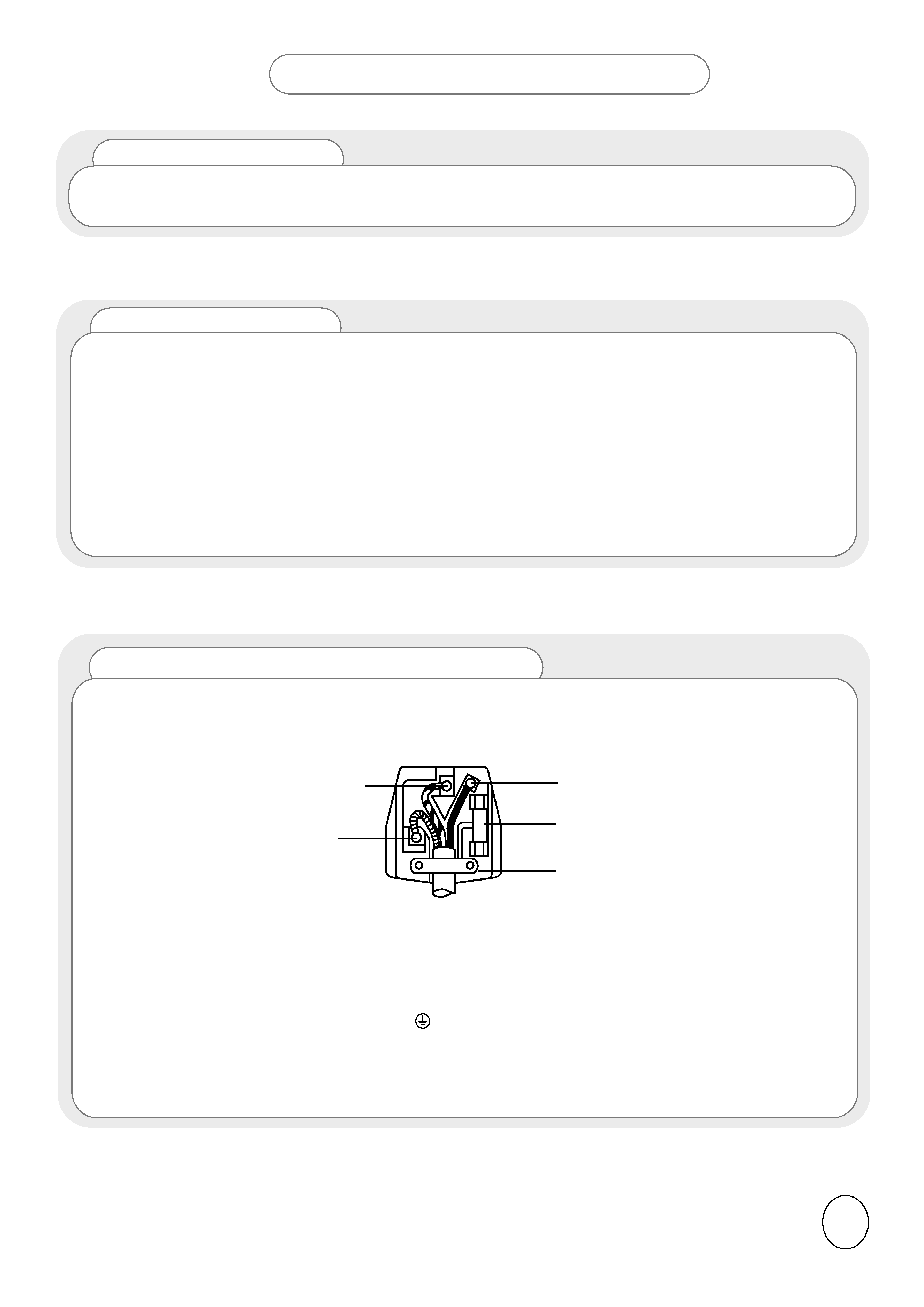
IMPORTANT! The wires in the mains lead are coloured in accordance with the following code ;
Green and Yellow = Earth, Blue = Neutral, Brown = Live
As these colours may not correspond with the coloured markings identifying the terminals in your plug, proceed
as follows:
1. The wire which is coloured GREEN and YELLOW must be connected to the terminal in the plug which is
marked with the letter E or by the EARTH symbol
or coloured GREEN or GREEN and YELLOW.
2. The wire coloured BLUE must be connected to the terminal with the letter N or coloured BLUE or BLACK.
3.The wire coloured brown must be connected to the terminal marked with the letter L or coloured BROWN or
RED.
Green and Yellow to Earth
Blue to Neutral
Brown to Live
Fuse
Cord Clamp
3
Mains Supply
This equipment is designed to operate on 220-240V AC 50Hz only. Do not operate on DC power
supplies or other voltages. Before connecting to the mains, please read the following instructions
carefully.
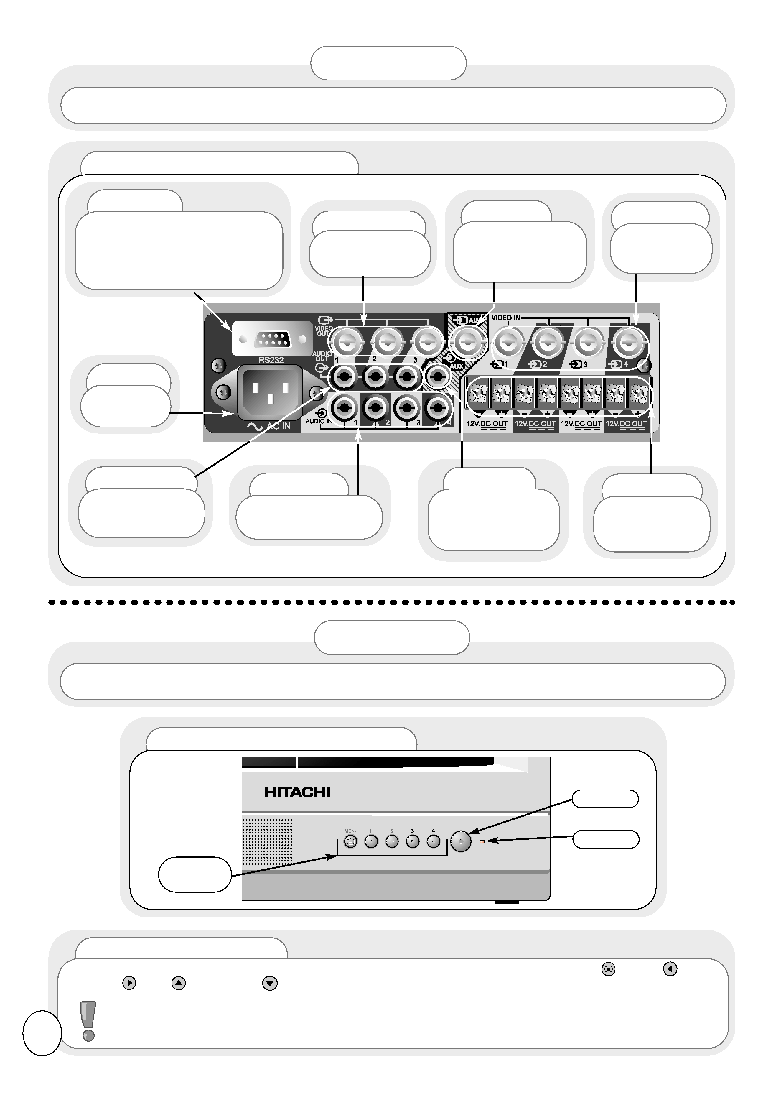
Front View of Controls
Rear View of Monitor
RS232
For further details, please
contact HITACHI Sales division.
(Refer to the back cover of this
manual for contact numbers.)
Video Out
To VCR or
other monitor.
Video In
Video in
from cameras.
Aux
Video input
from an external
device e.g. a VCR.
Audio Out
To VCR or
other monitor.
12V DC
Power
supplies for
cameras.
Audio In
Audio input for
use with cameras.
AC In
Mains
Socket
Aux
Audio input
from an external
device e.g. a VCR.
When you are satisfied that all equipment has been connected correctly, switch on the monitor and all
attached equipment. The red LED indicator on the front of the monitor will light and 2 tones will sound.
OPERATION
Control
Buttons
ON/OFF
LED
The view below shows the rear of your monitor. Please ensure that the cameras and all external equipment is
connected correctly before switching on the monitor or any of the attached equipment.
SET-UP
Monitor Controls
All control for this monitor, other than ON/OFF, is via the five front control buttons, MENU
, LEFT
,
RIGHT
, UP
and DOWN
.
These controls are dual function. Please see opposite for details.
Please Note : The Control buttons above are used to access, change and store the many different
functions and options available on this monitor. Please read this manual carefully for full details of
these features.
4
Monitor Controls - cont.
Once the monitor has been set up to your requirements using the menus as shown in this manual, you may
find the following features useful.
MENU
- Press to show the Main Menu.
BUTTON 1(LEFT)
- Press to show Volume bar, then use the LEFT/RIGHT buttons to adjust the volume. (This does
not change the default volume which is set in the Main Menu - see later).
BUTTON 2(RIGHT)
- Press to show the active camera, then use the LEFT/RIGHT buttons to change the active
camera. Please Note: The AUX input is only accessible via this method.
BUTTON 3 (DOWN) - Press to stop the cameras cycling and zoom the active camera to the full screen. If the
cameras are not cycling, the current active camera will zoom to the full screen. If you want to
change the active camera, press the LEFT/RIGHT buttons to select the desired camera view.
Press the DOWN button again to return to the previous Mode. Also, if in full screen mode,set to
Cycle, the cycling will stop.
BUTTON 4 (UP)
- Press to `freeze' all the camera views in Quad picture mode. Press again to release.
Press the MENU button on the front of the monitor to obtain
Main Menu.
1
To adjust the volume, press the LEFT/RIGHT buttons on the
front of the monitor.
2
VOLUME
5
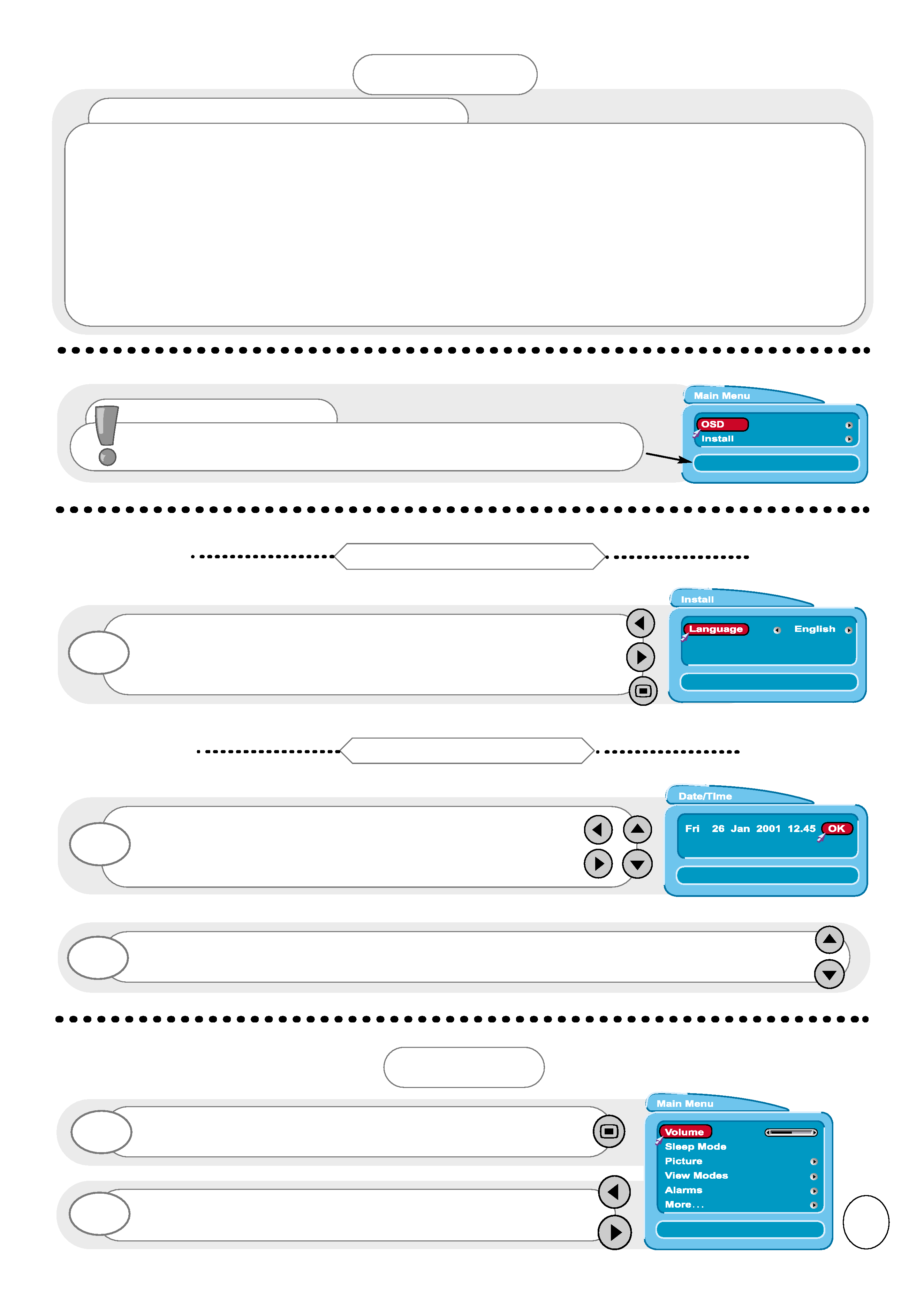
When the monitor is first switched on, the first screen will ask
you to choose the language of your monitor's display. Press the
LEFT/RIGHT buttons to choose your desired language, and the
MENU button to exit.
1
Setting the Language
Once all the options have been entered, highlight OK and press the UP/DOWN buttons to
confirm.
2
You will now be asked to enter the correct date and time.
Highlight each option with the LEFT/RIGHT buttons. The
highlighted option will turn RED. Press the UP/DOWN
buttons to change.
1
Setting the Date & Time
OPERATION
On Screen Help
When using the menus of your monitor, extra on screen help will
be displayed in this window to assist you in setup and operation.